 Schütz,Leistungsschalter,Sensor,Encoder,SPS,Konverter

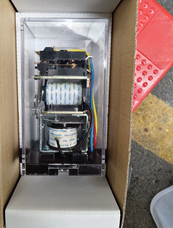

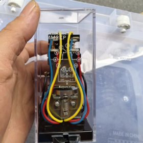
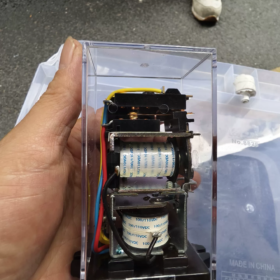
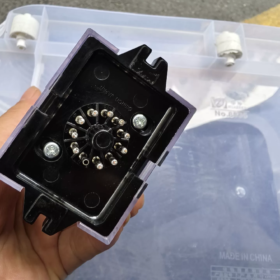
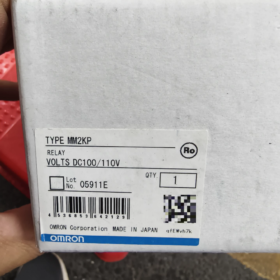
MM2KP = MMK Series, 2-Pole (DPDT), cased, Plug-in mechanical latching (bistable dual-coil) Relais
Modelldefinition:
MM: MM series power-type latching relay
2: 2 contact sets, DPDT (2C)
K: Mechanical latching (dual coil, SATZ / ZURÜCKSETZEN, pulse-operated, retains contact state after power loss)
P: Plastic enclosed housing, plug-in socket mounting type
✅ Key Specifications
- Kontakte: DPDT 2C, silver Ag contacts
Rated load: AC220V 5A; DC24V 4A
Max switching voltage: AC250V / DC250V; Max switching current 5A
Max switching capacity: 1100VA / 96W
- Coils (Two independent coils: SATZ + ZURÜCKSETZEN)
Available coil voltages:
Wechselstrom: 6/12/24/100(110)/200(220)VAC
Gleichstrom: 12/24/48/100(110)/125/200(220)VDC
Beispiel: MM2KP DC24: SET coil 275Ω / 87mA; RESET coil 220Ω / 109mA
Drive requirement: Pulse ≥100ms, continuous power not required. Contact state remains after coil power removal.
- Timing
Operate time ≤60ms; Reset time ≤30ms
Maximale Betriebsfrequenz: 1800 Operationen/Stunde
- Lebensdauer
Mechanisches Leben: ≥2,500,000 operations
Elektrisches Leben: ≥500,000 operations (bei Nennlast)
- Umgebungsbedingungen: -10~+55℃, keine kondensation; Humidity 5~85%RH
- Montage: 11-pin socket (PL11 / 11PFA), socket installation; Gewicht ca. 375G
- Spannungsfestigkeit: Coil to contact AC2000V, between contacts of different poles AC2000V
✅ Operating Principle (Höhepunkte)
Dual-coil mechanical latching (bistable relay)
Apply pulse to SET coil → contacts switch and mechanically latch. Contact state is maintained after coil power off.
Apply pulse to RESET coil → contacts reset and latch.
Vorteile: Zero steady-state power consumption. Ideal for power, energy storage and signal circuits requiring state retention after power loss.
Unterscheidung: MM2K = bare relay without housing; MM2KP = cased P type; MM2XKP = enhanced version for DC loads.
✅ Typical Application Scenarios
Power monitoring, relay protection circuits, signal memory circuits
Gebäudebrandschutz, emergency power supply, energy storage control
Remote maintained switches, state latching for primary/secondary circuits
Suitable for applications requiring switch state retention and prohibiting continuous coil energization.
✅ Selection & Ersatzinformationen
- Extended series:
MM3KP: 3-pole 3C; MM4KP: 4-pole 4C; MM2XKP: DC-load enhanced model
- Domestic replacement guideline: Dual-coil bistable relay, DPDT 5A, 11-pin socket type. Pay attention to SET/RESET coil resistance values. Single-coil bistable relays cannot be directly substituted.
- Common failure points:
Pulse width <100ms → unreliable SET / ZURÜCKSETZEN
Swapped SET and RESET coils will not burn the relay, but state switching fails
Contact erosion: No absorption circuit (varistor / Freilaufdiode) für induktive Lasten
✅ Matching Socket
PL11 / 11PFA (11-pin socket)
OMRON MM2KP Overall Dimensions (Official Datasheet, Einheit: mm)
Relaiskörper (without socket): W54.5 × D80.5 × H119 (max)
W: 54.5 max (Breite)
D: 80.5 max (Tiefe)
H: 119 max (total height including transparent cover)
Overall Height when assembled with PL11 socket
MM2KP mounted on PL11 socket: Total height approx.151mm
Befestigungslöcher (direct base mounting, no socket)
2 × Φ4.5 mounting holes, center distance: 22 ±0.2 mm
Gewicht
MM2KP: ca. 375 G
Series dimension comparison (for cabinet layout)
MM2KP: 54.5(W) ×80.5(D) ×119(H)
MM3KP: 64.5(W) ×80.5(D) ×119(H)
MM4KP: 70.5(W) ×80.5(D) ×119(H)
Notizen:
- MM2XKP (DC load enhanced version) shares identical outer dimensions with MM2KP, with curved protective plate on side. Cabinet side clearance ≥55mm is recommended.
- Dimension tolerance: ±0.4mm for non-specified dimensions.
OMRON MM2KP Mechanical Latching Relay Operating Principle
MM2KP is a dual-coil mechanically latched bistable relay. The key difference from conventional relays: Coils are energized only during state transition. No continuous power required in steady state. Contact state is locked by internal mechanical latch and magnetic structure, retained after power loss.
Interne Struktur
Two independent coils: SET coil and RESET coil, electrically separated. Armature coupled with mechanical latch assembly + DPDT (2C) contact sets.
SET coil: Drives mechanism to switch contacts to NO closed position and latch.
RESET coil: Reverse drive to release latch, contacts return to NC position.
Full Operating Sequence
- Initial reset state
Mechanical latch stays at reset position: NC geschlossen, KEIN geöffnet. Both coils de-energized. State maintained purely by mechanical latch with zero coil power consumption.
- SET operation (SET pulse)
Apply pulse ≥100ms to SET coil (DC/AC available). Electromagnetic force pulls armature and flips mechanical latch to locked position.
Contacts switch: NEIN geschlossen, NC geöffnet.
After pulse termination and SET coil de-energized, mechanical latch holds position without rebound.
DC version operate time ≤60ms; AC version ≤30ms.
- RESET operation (RESET pulse)
Apply pulse ≥100ms to RESET coil. Electromagnetic force pushes armature in reverse direction to release mechanical latch.
Contacts return to initial state: KEIN geöffnet, NC geschlossen.
After RESET coil de-energized, mechanical latch retains reset state again.
✅ Critical rule: SET and RESET coils must not be energized simultaneously. Concurrent energization will result in SET state, which is an invalid drive condition and prohibited in circuit design.
Comparison with conventional relays & permanent magnet bistable relays
- Standard electromagnetic relay: Contact closed only when coil continuously energized; contacts release immediately after power loss, state lost.
- MM2KP: Mechanical latch is the primary holding mechanism; magnetic force only toggles the latch. Zero steady-state power, state retention after power loss. Mixed coil voltages are available (z.B. SET AC220V, RESET DC24V).
- Permanent magnet bistable relay: State held by permanent magnet, no mechanical latch.
Core Electrical Key Points (Engineering Focus)
Minimum pulse width: 100MS. Shorter pulse causes unreliable occasional failure of SET/RESET.
Coils are pulse-only driven. Prolonged continuous energization will overheat and burn coils.
Bistable characteristic: State changes only upon receiving opposite pulse. Contact status remains unchanged during power drop and power reboot.
Terminal Logic Summary (PL11 11-pin socket)
SET coil: one pair of terminals
RESET coil: separate pair of terminals
Kontakte: 2 sets DPDT (Gewöhnliches C, Normalerweise geöffnet NEIN, Normalerweise geschlossener NC)
OMRON MM2KP Mechanical Latching Relay Application Scenarios
Core selection criteria: Pulse drive, power-off state retention, zero steady-state power consumption, DPDT transfer contacts, transparent cased housing + 11-pin socket mounting. Mainly used for memory and state latching circuits, widely adopted in power secondary systems.
- Energiesystem (Primäre Anwendung)
- Secondary signal memory circuit for HV/LV switchgear
Latching protection alarm: When fault triggers protection, protection device sends SET pulse. MM2KP latches alarm signal. Alarm remains active even if protection device loses power or fault disappears. RESET signal (manual or circuit) is required for reset, convenient for maintenance to trace transient faults.
- Circuit breaker position memory & remote signalling retention circuit
Record circuit breaker open/close status. Switch position is preserved during temporary loss of DC control supply. Remote signalling state will not be lost after power restart.
- Auxiliary latching circuit for relay protection
Model compliant with JEC-174D power auxiliary relay standard. Used for trip retention, interlock latching and fault signal circuits, replacing traditional mechanical signal relays.
- DC panel, UPS & energy storage cabinet state latching
Latch overvoltage, undervoltage and battery fault signals; fault record retained after power outage.
- Fire Protection & Emergency Power Systems
- Fire linkage signal memory: Triggered by fire alarm pulse, linkage output latched. Linkage state preserved after fire host power cycle, manuelles Zurücksetzen erforderlich.
- EPS emergency power supply, ATS cabinet: Fault state latching to record switching events.
- Industrielle Automatisierung & Gerätekontrolle
- Equipment fault memory, shutdown latching circuit
Werkzeugmaschinen, Produktionslinien, Pumpe & valve units: Überlast / emergency stop triggers SET pulse to latch shutdown. Equipment will NOT automatically resume operation after power restart until manual reset, Verbesserung der Sicherheit.
- State feedback circuit for remotely pulsed actuators (Ventile, dampers).
- Test benches and trial equipment: One-shot event memory to record trigger events.
- Schienenverkehr & Gebäudestromverteilung
- Audible & visual alarm latching circuit for ring main units and power distribution rooms.
- Power cabinets in metro / tunnel applications, event state retention during temporary power interruption.
✅ Selection Limitations (Technische Hinweise, Ungeeignete Anwendungen)
- Not for high-speed cycling: Max rated 1800 Operationen/Stunde, not applicable for high-frequency switching.
- Pulse control only: Continuous energization of SET/RESET coils is forbidden, coil burnout will occur.
- Kontaktbewertung: AC220V 5A, DC24V 4A. Not for high-current main circuits; only suitable for secondary signal circuits.
- Ambiente: -10~+55℃, condensation not permitted.
✅ Replacement Guidelines
Frequent DC load switching (DC110V): Select MM2XKP (enhanced contact model for DC)
More contact sets required: MM3KP (3 transfer contacts), MM4KP (4 transfer contacts)



NH42-63-318x560.png "Automatische Transferschalter vom Typ CHINT PC (ATS)NH42-63/4SZ")



