 Schütz,Leistungsschalter,Solarwechselrichter,Stromzähler,Solarbatterien

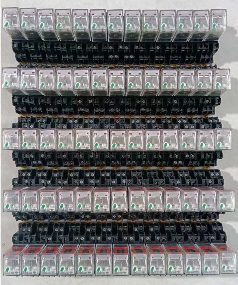

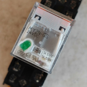
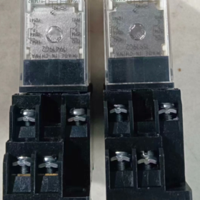
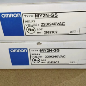
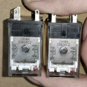
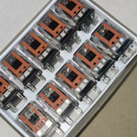
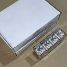
Der OMRON MY2N-GS AC220V ist ein 2-poliger Doppelschalter (DPDT) Steckbare Miniatur Zwischenrelais aus der OMRON MY-GS-Serie. Es ist der offizielle, verbesserte Ersatz für das klassische Vorgängermodell MY2N-J. Zu den Standardkonfigurationen gehört eine LED-Betriebsanzeige, mechanische Statusanzeige und manueller Testverriegelungshebel. Verwendung von Kontakten aus Silberlegierung, es zeichnet sich durch eine hohe Zuverlässigkeit aus, lange Lebensdauer und komfortable Verkabelung. Wird hauptsächlich zur SPS-Ausgangssignalverstärkung verwendet, Lastschaltung und Schaltungslogikumwandlung, Es handelt sich um eine universelle Grundkomponente für Schaltschränke der industriellen Automatisierung.
- Aufschlüsselung des Modellcodes
Vollständiges Standardmodell: MY2N-GS AC220/240V
MEIN: Produktserie, Allzweck-Miniatur-Leistungszwischenrelais
2: Anzahl der Kontaktsätze, 2 Sätze von Wechselkontakten (DPDT, 2 Normalerweise geöffnet + 2 Normalerweise geschlossen)
N: Standard-Steckklemmen mit integrierter Betriebsanzeige
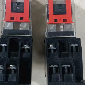
GS: Serie der nächsten Generation (Generationsstandard). Es ersetzt die ursprüngliche MY2N-J-Serie, ist mit einem zusätzlichen Verriegelungshebel ausgestattet, und sorgt für eine optimierte Kontakthaltbarkeit und elektrische Leistung.
AC220/240V: Bemessungsspulenspannung, Wechselstrom 220 ~ 240 V, kompatibel mit 50/60Hz-Stromversorgung.
Ergänzende Hinweise
Die meisten auf dem Markt erhältlichen Produkte sind standardmäßig mit einem Verriegelungshebel ausgestattet (Suffix -R), Unterstützung manueller Tests und Kontaktverriegelung.
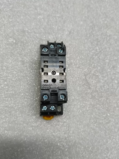
Passende Standard-8-Pin-Buchse: Schraubklemmentyp PYF08A, Steckklemme Typ PYF08A-PU.
- Wichtigste technische Spezifikationen
| Kategorie | Spezifikationen |
| Kontaktkonfiguration | 2 Sätze von Wechselkontakten (DPDT, 2NO+2NC) |
| Nennkontaktstrom | 5A (AC250V ohmsche Last); 5A (DC30V ohmsche Last) |
| Kontaktmaterial | Silberlegierung (AgSnO₂) |
| Nennspulenspannung | Wechselstrom 220 ~ 240 V, 50/60Hz |
| Spulenstromverbrauch | Ca. 1.2~1,5 VA |
| Betriebszeit | ≤ 20 MS |
| Release-Zeit | ≤ 20 MS |
| Mechanisches Leben | ≥ 50 Millionen Operationen |
| Elektrisches Leben | ≥ 100,000 Operationen (unter Nennwiderstandslast) |
| Dielektrische Spannungsfestigkeit | 2kV Wechselstrom / 1min (zwischen Spule und Kontakten) |
| Statusanzeige | Rote LED-Anzeige (leuchtet, wenn es mit Strom versorgt wird) + Mechanischer Anzeigehebel |
| Montageart | Plug-in-Typ, Wird mit passender Standardsteckdose verwendet |
| Anzahl der Pins | 8 Stifte |
| Betriebsumgebungstemperatur | -40℃ ~ +70℃ (Keine Kondensation) |
| Schutz vor Eindringen | IP40 (Relaiskörper) |
| Zertifizierungen | CE, UL, CSA, VDE, CQC |
- Vollständige Modellliste der gleichen Serie
4.1 Klassifiziert nach Kontaktsätzen
| Kontaktsätze | Pin-Anzahl | Standardmodell | Modell mit Feststellhebel | Nennkontaktstrom |
| 2 Wechslerkontakte (2NO+2NC) | 8 Stifte | MY2N-GS | MY2N-GS-R | 5A |
| 4 Wechslerkontakte (4NO+4NC) | 14 Stifte | MY4N-GS | MY4N-GS-R | 5A |
4.2 Gängige Spulenspannungsnennwerte
Die gesamte Serie unterstützt die folgenden Standardspannungen, nur durch das Spannungssuffix unterschieden:
Gleichstrom: DC12V, DC24V, DC48V
Wechselstrom: AC24V, AC110/120V, AC200/220V, AC220/240V
- Pin-Belegung & Verkabelungsanweisungen
5.1 Pin-Definition (Draufsicht von der Verdrahtungsseite der Steckdose)
| Pin-Nr. | Funktion | Beschreibung |
| 13 (A1) | Ein Ende der Spule | An stromführendes AC220V-Kabel anschließen |
| 14 (A2) | Das andere Ende der Spule | An AC220V-Neutralleiter anschließen |
| 9 | Gemeinsames Terminal 1 (COM1) | Gemeinsamer Pin für den 1. Kontaktsatz |
| 1 | Normalerweise geschlossen 1 (NC1) | Leitet mit Pin 9 wenn die Spule stromlos ist |
| 5 | Normalerweise geöffnet 1 (Nr. 1) | Leitet mit Pin 9 wenn die Spule unter Strom steht |
| 12 | Gemeinsames Terminal 2 (COM2) | Gemeinsamer Pin für den 2. Kontaktsatz |
| 4 | Normalerweise geschlossen 2 (NC2) | Leitet mit Pin 12 wenn die Spule stromlos ist |
| 8 | Normalerweise geöffnet 2 (NO2) | Leitet mit Pin 12 wenn die Spule unter Strom steht |
5.2 Vorsichtsmaßnahmen bei der Verkabelung
- Für die Wechselstromspule ist keine Polarität erforderlich. A1 und A2 können beliebig an stromführendes Kabel und Neutralleiter angeschlossen werden.
- Für induktive Lasten (Schütze, Magnetventile), Es wird empfohlen, einen Überspannungsschutz anzuschließen (RC-Dämpferschaltung) parallel geschaltet, um die Kontaktlebensdauer zu verlängern.
- Nicht über den Nennstrom hinaus betreiben. Verwenden Sie Schütze zum sekundären Schalten von Hochleistungslasten.
- Mit dem Verriegelungshebel können die Kontakte manuell geschlossen werden, die auf die Inbetriebnahme im ausgeschalteten Zustand und die Schaltkreisprüfung angewendet wird.
- Typische Anwendungen
Verstärken Sie SPS-Ausgangssignale, um Lasten wie Magnetventile anzusteuern, Schütze und Kontrollleuchten
Konvertierung der Schaltungslogik, Pegelanpassung und Signaltrennung innerhalb von Schaltschränken
Start-Stopp-Steuerung, Signalrelais und Schaltungserweiterung für automatisierte Anlagen
Sekundärkreissteuerung und Schutzsignalübertragung in Energieverteilungssystemen
- Allgemeine Fehlerbehebungsmatrix
| Fehlerphänomen | Grundursache | Schritt-für-Schritt-Lösungen |
| Das Relais funktioniert nicht und die Anzeige bleibt nach dem Einschalten ausgeschaltet | 1. Ungewöhnliche Versorgungsspannung / Defekte Verkabelung | 1. Messen Sie die Spannung zwischen A1 und A2, um die normale AC220V-Versorgung zu bestätigen |
| 2. Offene Spule durchgebrannt | 2. Spulenwiderstand testen; Ersetzen Sie das Relais, wenn ein offener Stromkreis festgestellt wird | |
| 3. Schlechter Kontakt zur Steckdose | 3. Setzen Sie das Relais wieder ein und reinigen Sie die Sockelstifte | |
| Die Anzeige leuchtet, aber die Kontakte haben keinen Ausgang | 1. Verschweißte oder oxidierte Kontakte mit schlechter Leitfähigkeit | 1. Testen Sie die Kontaktkontinuität; Tauschen Sie das Relais aus, wenn die Kontakte beschädigt sind |
| 2. Defekte Verkabelung auf der Lastseite | 2. Überprüfen Sie die Verkabelung und die Integrität des Lastkreises | |
| 3. Beschädigte Kontakte durch Überlastung | 3. Laststrom überprüfen; Wählen Sie bei Überlastbedingungen ein Modell mit höherer Nennleistung | |
| Die Kontakte lösen sich nicht und kleben nach dem Ausschalten zusammen | 1. Kontaktschweißen durch Lichtbogen unter starkem Strom | 1. Ersetzen Sie das Relais und installieren Sie Überspannungsschutzkomponenten |
| 2. Mechanischer Stau oder defekte Rückholfeder | 2. Überprüfen Sie den internen Mechanismus; Ersetzen Sie das gesamte Relais, wenn eine mechanische Blockierung auftritt | |
| Ungewöhnliches Brummgeräusch während des Betriebs | 1. Unvollständige Ankeranziehung wegen Unterspannung | 1. Versorgungsspannung auf den Nennbereich einstellen |
| 2. Öl oder Staub auf der Kernoberfläche | 2. Tauschen Sie das Relais aus; Zerlegen Sie den Kern nicht manuell | |
| Übermäßige Erwärmung oder Durchbrennen der Spule | 1. Überspannungsnetzteil | 1. Stellen Sie sicher, dass die Versorgungsspannung dem Nennwert entspricht; Überspannungsbetrieb ist verboten |
| 2. Langfristiges Hochfrequenzschalten | 2. Reduzieren Sie die Schaltfrequenz oder verwenden Sie Halbleiterrelais |
- Referenz alternativer Modelle
Originaler Markenersatz: MY2N-J AC220V (Vollständig Pin-kompatibel, ohne Verriegelungshebel)
Inländische Alternativen: Chint NJX-13FW/2Z AC220V, Delixi CDZ9-52P AC220V
Importierte Äquivalente: Schneider RXM2LB2P7, ABB CR-MX230AC2L, Phoenix Contact REL-MR-230AC/21
Fehlerbehebungsmatrix für OMRON MY2N-GS AC220V 5A Relais
Dieses Modell verfügt über: 2 Sätze von Wechselkontakten, 8-Pin-Steckstruktur, LED-Betriebsanzeige und Verriegelungshebel. Nachfolgend finden Sie den Leitfaden zur Fehlerbehebung, sortiert nach der Reihenfolge der Vor-Ort-Inspektion (von einfach bis komplex), deckt Störungen ab, die durch elektrische Störungen verursacht werden, mechanische und Installationsprobleme.
| Fehlerphänomen | Grundursache | Schritt-für-Schritt-Lösungen |
| Kein Betrieb und rote LED-Anzeige erlischt nach dem Einschalten | 1. Fehler im externen Stromkreis: Keine Spannung, lose Verkabelung, Strom-/Neutralleiter defekt | 1. Wechselspannung zwischen Buchse Pin messen 13(A1) und Pin 14(A2). Bestätigen Sie die Spannung innerhalb von AC220V ±10 %.. Überprüfen Sie vorgeschaltete Schalter und Klemmen, wenn keine Spannung erkannt wird. |
| 2. Schlechter Buchsenkontakt: Oxidierte Stifte oder lockere Verbindung zwischen Relais und Sockel | 2. Strom abschalten, Ziehen Sie das Relais heraus, Reinigen Sie die Stifte und Buchsenkontakte von Oxid, dann wieder fest einsetzen. | |
| 3. Offene Spule durchgebrannt: Überspannungsausfall, Alterung der Isolierung oder Überspannungseinwirkung | 3. Spulenwiderstand messen. Der normale Widerstand liegt bei ca. 12~15kΩ bei 25℃. Ersetzen Sie das Relais, wenn ein offener Stromkreis oder ein ungewöhnlicher Widerstand auftritt. | |
| 4. Verriegelungshebel klemmt in Freigabeposition (für -R-Version) | 4. Stellen Sie den oberen Verriegelungshebel wieder in die normale Position, um mechanische Blockaden zu beseitigen. | |
| LED leuchtet, aber Kontakte haben keinen Ausgang | 1. Falsche Verkabelung für Kontaktkreis: Gemischte Verbindung von Gemeinsamem, NO- und NC-Klemmen | 1. Überprüfen Sie die Pin-Definition: COM-Anschlüsse sind Pin 9 und Pin 12; KEINE Anschlüsse sind Pin 5 und Pin 8. Stellen Sie sicher, dass die NC-Pins nicht falsch angeschlossen sind. |
| 2. Defekter Lastkreis: Kein Strom für die Last oder lose Anschlüsse | 2. Drücken Sie den Verriegelungshebel, um die Kontakte manuell zu schließen und den Durchgang zu testen. Falls noch geöffnet, Überprüfen Sie die Stromversorgung und Verkabelung auf der Lastseite. | |
| 3. Verbrannte oder oxidierte Kontakte durch langfristige Überlastung und Lichtbogen | 3. Ersetzen Sie das Relais, wenn die Kontakte aufgrund von Durchbrennen oder Oxidation nach dem manuellen Schließen offen bleiben. | |
| 4. Interner Mechanismus blockiert: Die Spule zieht normal ein, aber die Verbindung treibt die Kontakte nicht an | 4. Ersetzen Sie das Relais, wenn während des manuellen Betriebs eine mechanische Blockierung festgestellt wird. | |
| Die Kontakte bleiben geschlossen und können nach dem Ausschalten nicht freigegeben werden | 1. Kontaktschweißen: Verursacht durch Überlastung, Kurzschluss oder Lichtbogen ohne Überspannungsschutz bei induktiven Lasten | 1. Unterbrechen Sie die Stromversorgung und stellen Sie sicher, dass an der Spule keine Spannung anliegt. Verriegelungshebel zurücksetzen und prüfen, ob Kontakte geöffnet sind. |
| 2. Rückholfeder defekt: Elastizitätsdämpfung durch häufiges Schalten und hohe Temperaturen | 2. Ersetzen Sie das Relais sofort, wenn die Kontakte nach dem Zurücksetzen immer noch geschlossen sind. Verschweißte Kontakte können nicht zur Wiederverwendung repariert werden. | |
| 3. Fremdkörperstau: Staub oder Eisenspäne stecken im Anker oder Kontaktmechanismus fest | 3. Stellen Sie sicher, dass der Laststrom 5 A nicht überschreitet. Installieren Sie einen RC-Überspannungsschutz für induktive Lasten. | |
| 4. Zufällige Verriegelung des Verriegelungshebels nach manuellem Test | 4. Umliegenden Staub und Eisenspäne reinigen; Tauschen Sie das Relais aus, wenn die mechanische Störung nicht behoben werden kann. | |
| Ungewöhnliches Brummgeräusch während des Betriebs | 1. Eine niedrige Versorgungsspannung führt zu unvollständiger Kernanziehung und Ankervibrationen | 1. Messen Sie die Spulenspannung und halten Sie sie innerhalb von AC220V ±10 %.. Überprüfen Sie den Spannungsabfall im Stromkreis, wenn die Spannung niedrig ist. |
| 2. Öl, Staub oder Rost auf der Kernoberfläche führen zu einem übermäßigen Magnetspalt | 2. Setzen Sie das Relais wieder vollständig ein und ziehen Sie die Befestigungsschrauben von Sockel und Schiene fest. | |
| 3. Kurzschlussring am Kern defekt (Einzigartiger Fehler der Wechselstromspule) | 3. Ersetzen Sie das Relais, wenn das Geräusch nach der Reinigung der Kernoberfläche weiterhin besteht (beschädigter Kurzschlussring oder verschlissener Kern). | |
| 4. Lockerer Sitz zwischen Relais, Steckdose und DIN-Schiene verursachen Resonanz | 4. Passen Sie die Montageposition an, um den Resonanzspalt zu beseitigen. | |
| Übermäßige Erwärmung oder Durchbrennen der Spule | 1. Starke Überspannung überschreitet den oberen AC240V-Grenzwert und führt zu einer Spulenüberlastung | 1. Überwachen Sie die Versorgungsspannung genau; Langfristiger Überspannungsbetrieb ist verboten. |
| 2. Eine zu hohe Schaltfrequenz führt zu einer kumulativen Überhitzung über die Isolationsgrenze der Klasse B hinaus | 2. Schalthäufigkeit begrenzen ≤ 20 Mal pro Minute. Verwenden Sie für hochfrequente Arbeitsbedingungen ein Halbleiterrelais. | |
| 3. Eine schlechte Wärmeableitung bei hohen Umgebungstemperaturen beschleunigt die Alterung der Isolierung | 3. Verbessern Sie die Wärmeableitung im Schrank. Von wärmeerzeugenden Bauteilen wie Wechselrichtern und Schützen fernhalten. Die Umgebungstemperatur darf 70℃ nicht überschreiten. | |
| 4. Durch Überspannung und Überspannung verursachter Isolationsausfall | 4. Schließen Sie den RC-Überspannungsschutz parallel zur Spule an, um vorübergehende Überspannungen beim Ausschalten zu unterdrücken. | |
| Schlechter Kontakt, intermittierendes Signal | 1. Oxidation und Staub auf der Kontaktfläche führen zu hohem Kontaktwiderstand | 1. Strom abschalten, Ziehen Sie das Relais heraus, Reinigen Sie die Kontakte und Stifte von Oxid, dann fest einführen. |
| 2. Ein zu geringer Laststrom kann die Oxidschicht nicht durchbrechen (Low-Level-Signalkreis) | 2. Verwenden Sie vergoldete Kontaktrelais oder erhöhen Sie den Stromkreis ordnungsgemäß für Anwendungen mit Signalen mit niedrigem Pegel. | |
| 3. Ermüdung oder Oxidation der Buchsenstifte führen zu lockerer Verbindung | 3. Ersetzen Sie die passende PYF08A-Buchse, wenn die Stifte ihre Elastizität verlieren oder stark oxidiert sind. | |
| 4. Unvollständiges Einsetzen des Relais führt zu mechanischem Wackelkontakt | 4. Ersetzen Sie das Relais durch ein neues, wenn ein intermittierender Fehler häufig auftritt, um eine wiederholte Oxidation zu verhindern. | |
| Ungewöhnliche Helligkeit oder Flackern der Anzeige | 1. Instabile Stromversorgung mit großen Spannungsschwankungen | 1. Messen Sie die Spulenspannung und bestätigen Sie eine stabile Stromversorgung ohne starke Schwankungen. |
| 2. Schlechter Buchsenkontakt führt zu unterbrochener Spulenstromversorgung | 2. Setzen Sie das Relais wieder ein und reinigen Sie die Stifte, um Wackelkontakte zu vermeiden. | |
| 3. Alterung und Ausfall des Strombegrenzungswiderstands für die Anzeige | 3. Messen Sie den Spulenwiderstand, wenn die Anzeige bei stabiler Spannung nicht richtig funktioniert. Ersetzen Sie das Relais sofort, wenn es zu einem Kurzschluss zwischen den Windungen kommt (geringer Widerstand) erkannt wird. | |
| 4. Kurzschluss zwischen den Spulenwindungen führt zu abnormaler Spannungsteilung | 4. Eine vorübergehende Verwendung ist zulässig, wenn nur der Indikator ausfällt, während die Kontakte normal funktionieren. Ein Chargenaustausch wird empfohlen. |
Ergänzende Hinweise zur Fehlerbehebung
- Inspektionspriorität: Befolgen Sie die Reihenfolge: Externe Stromversorgung → Buchsenkontakt → Relaiskörper. 80% der Fehler werden durch Verkabelungs- und Steckdosenprobleme verursacht. Priorisieren Sie diese Prüfungen, um unnötigen Austausch zu vermeiden.
- Sicherheitsvorschriften: Halten Sie bei Live-Tests die elektrischen Sicherheitsstandards ein. Unterbrechen Sie die Stromversorgung, bevor Sie Kontakte und Spulen überprüfen, um Stromschläge und Kurzschlüsse zu vermeiden.
- Referenz zur Lebensdauer: Die elektrische Nennlebensdauer beträgt 100,000 Betrieb unter ohmscher Last. Die Lebensdauer verringert sich um mehr als 50% für induktive Lasten. Bei Erreichen der Servicegrenze empfiehlt sich ein regelmäßiger Austausch.


")


NH42-63-318x560.png "Automatische Transferschalter vom Typ CHINT PC (ATS)NH42-63/4SZ")


