 Schütz,Leistungsschalter,Solarwechselrichter,Stromzähler,Solarbatterien

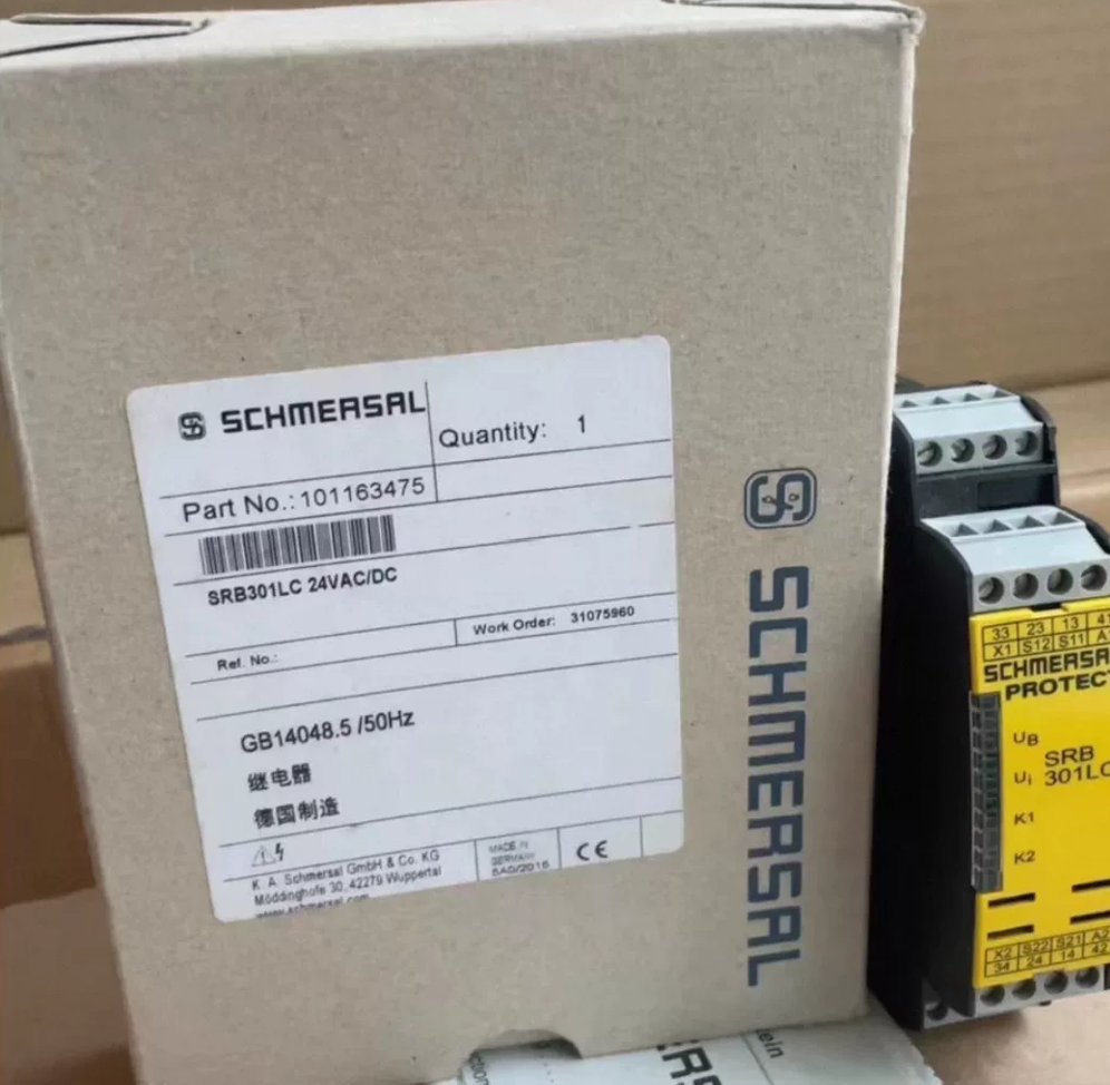

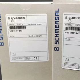
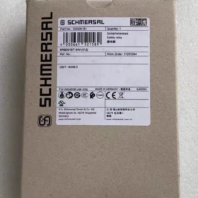
Aufschlüsselung des Modellcodes
- SRB: Schmersal Safety control module of PROTECT series (Sicherheitsrelais)
- 301: Basismodell, dual-channel passive input, Not-Aus / Schutztürüberwachung
- LC: Schraubklemme (0.25~2.5mm²), built-in glass fuse, no electronic fuse
- 24V: Universal supply voltage 24V AC/DC
- 101163475: Unique factory order number; Alternative order number: 101165472
- Grundlegende elektrische Spezifikationen
2.1 Stromversorgung
Nennspannung: Dual-purpose 24V AC/DC
DC range: 20.4~28.8V DC (-15%/+20%)
Wechselstrom 50/60 Hz: 20.4~26.4V AC (±10 %)
Stromverbrauch: 1.7W / 1.9VA
Circuit fuse: 0.5A gG glass fuse (standard for LC version)
2.2 Input Circuit (Dual-channel Monitoring)
2 independent safety inputs A/B, compatible with passive contacts: Not-Aus-Taster, safety gate switches, magnetic safety switches
Equipped with wire break detection and ground fault detection; No cross-channel short-circuit detection
Max cable length: 2500M (2.5mm² Kabel, loop resistance ≤40Ω)
2.3 Ausgangskontakte (Core for Safety Rating)
Main safety contacts: 3 Normalerweise geöffnet (NEIN) forced-guided contacts, Stop Category 0
Auxiliary signal contact: 1 Normalerweise geschlossen (NC) fault feedback output (ERR diagnosis)
Contact protection fuses: 6A T for safety circuit; 2A T for auxiliary circuit
Max switching frequency: 5Hz; Contact resistance ≤100mΩ
- Safety Certification Ratings (Mechanical Safety Standards)
IN ISO 13849-1: PL e / Kat.4 (Highest mechanical safety level)
IEC 61508: SIL 3
Compliant standards: IN 60947-5-1, IN ISO 13850 (Not-Aus), IN 60204-1 Machinery Standard
- Mechanisch & Umgebungsparameter
Montage: Standard snap-on 35mm DIN rail mounting
Schutzklasse: IP20 (For cabinet internal use only)
Betriebstemperatur: -25℃ ~ +45℃
Gehäuse: Glass fiber reinforced flame-retardant plastic
Gewicht: Ca. 249G
Terminals: Typ mit Schraubklemme, suitable for 0.25~2.5mm² single/multi-strand wires
- Funktionen & Typische Anwendungen
5.1 Kernfunktionen
Dual-channel cross-check; All safety outputs cut off immediately upon single-channel wire break or ground fault
Process passive contact signals (Not-Aus, Sicherheitstore, door interlock switches)
ERR fault output for external PLC / indicator light diagnosis
No automatic reset; Safety circuit must be reclosed to reset after fault clearance
5.2 Typische Anwendungen
Safety circuit monitoring for machine tools, Verpackungsausrüstung, automatische Produktionslinien, Spritzgießmaschinen, logistics sorting systems, lithium battery equipment and rail transit equipment
- Series Model Comparison (Auswahlreferenz)
| Modellsuffix | Terminaltyp | Fuse Type | Bestellnummer |
| LC | Screw terminal 0.25~2.5m㎡ | Glass fuse | 101163475 (Dieses Modell) |
| LCI | Plug-in screw terminal 0.25~2.5m㎡ | Electronic fuse | Separate order number |
| LCI/7 | Plug-in cage clamp terminal 0.25~1.5m㎡ | Electronic fuse | Separate order number |
| LC/B | Compatible with active safety light curtain signals | Glass fuse | 101177962 |
- Critical Risk Warnings
- Only applicable to passive contact safety switches. For safety light curtains (active AOPD), select model SRB301LC/B with suffix B
- Stop Category 0: Main circuit power cut-off with instantaneous stop; Not suitable for equipment requiring delayed braking
- Forced-guided contacts shall not be connected in parallel for capacity expansion; External contactors are required for heavy loads
- Must be matched with Cat.4 dual-channel safety components; Single-channel wiring cannot achieve PL e rating
Full Output Contact Capacity Specifications of SRB301LC-24V (Teile-Nr. 101163475)
- 3 Main Safety Normally Open Contacts (13-14 / 23-24 / 33-34)
1.1 Standard Rated Capacity for Resistive Loads
Max voltage: 250 VAC
Nennstrom: 6 A (AC-1 resistive)
Minimum reliable switching capacity: 10 V / 10 mA (to avoid contact non-conduction)
1.2 Standard Utilization Categories (IN 60947-5-1)
AC-15 (Induktive Lasten: AC solenoid valves / Schütze): 230 VAC / 6 A
DC-13 (Induktive Lasten: DC solenoid valves): 24 VDC / 6 A
1.3 Peak / Short-term Parameters (For Reference Only, Not for Continuous Operation)
The datasheet states a short-term limit of 8A. For engineering continuous loads, sizing shall be based on 6A. Freewheeling diodes or varistors shall be connected in parallel for arc suppression on inductive loads.
1.4 Matched Protection Fuse
Standard 6A time-lag fuse for safety circuit; Higher rated fuses are strictly prohibited.
- 1 Auxiliary Normally Closed Fault Contact (41-42 ERR Diagnosis)
Nennkapazität: 24 VDC / 2 A
Matched fuse: 2A time-lag fuse; Only for small signal loops such as PLC feedback and fault indicator lights, not for heavy loads.
- Schlüsselauswahl & Operation Restrictions
- Parallel connection of the three safety contacts for capacity expansion is forbidden. External safety contactors must be used for loads exceeding 6A.
- Stop Category 0 with instantaneous cut-off, suitable for cutting off main contactor coil circuits via emergency stops and safety gates.
- Arc suppression circuits are mandatory for inductive loads (Magnetventile, Spulen), otherwise contact service life will be drastically shortened.
- Derating is required at ambient temperature above 40℃; Max switching frequency is 5Hz.
Official Standard Response & Delay Specifications of SRB301LC-24V (101163475)
- Trip Response Time (Cut-off triggered by emergency stop / Sicherheitstor, core safety index)
- Maximum rated dropout delay specified in official manual: ≤50 ms
- Typical measured value of SRB301LC/B with identical architecture: ≤25 ms (Total breaking time of main safety contacts after dual-channel fault or emergency stop input disconnection)
> Notiz: 50ms is the conservative upper limit from the manufacturer. Under normal engineering operating conditions, cut-off is generally completed within 20~30ms, complying with Stop Category 0 emergency stop safety regulations.
- Make Delay (Safety circuit recovery, contact closing)
- Make delay for manual start via reset button: ≤20 ms (Output energized after safety gate closed and reset button pressed)
- Make delay under auto-start mode: ≤300 ms (Scenario without reset button, auto-energization upon power-up)
- Typical basic make delay stated in general datasheets: ≈30 ms
- Supplementary Key Notes
- This response time covers the total duration of dual-channel input logic detection plus internal electromechanical relay breaking, not merely mechanical contact actuation time.
- Drahtbruch, cross-channel short-circuit and ground fault detection also cut off safety outputs within ≤50ms.
- Compared with LC/B light curtain version with trip time ≤25ms, the upper limit for SRB301LC-24V (standard passive contact model) is extended to 50ms. 50ms shall be adopted for safety distance calculation in SISTEMA safety assessments.
- Upper switching frequency limit: 5Hz; Minimum full cycle make-break period: 200MS. High-frequency operation is not allowed.
- Reference for Safety Calculation During Selection
If the equipment requires total shutdown reaction time (schalten + Relais + Schütz), adopt the conservative value of 50ms for this relay to calculate safety distance.
 8-Port Industrial Layer 2 Hub")


")
NH42-63-318x560.png "Automatische Transferschalter vom Typ CHINT PC (ATS)NH42-63/4SZ")


