 Schütz,Leistungsschalter,Solarwechselrichter,Stromzähler,Solarbatterien

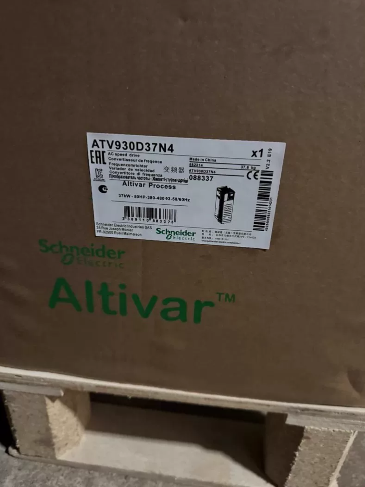


Der ATV930D37N4 ist ein High-End-Standard Antrieb mit variabler Geschwindigkeit aus Schneider Electrics Altivar Process ATV900-Serie, Entwickelt für die Prozessindustrie. Die Nennleistung beträgt im Normalbetrieb 37 kW und im Hochleistungsbetrieb 30 kW, kompatibel mit 3-Phasen-Stromnetzen mit 380–480 V. Es verfügt standardmäßig über einen integrierten Brems-Chopper und EMV-Filter, mit Schutzart IP21. Optimiert für Dauerbetriebsbedingungen wie z. B. Lüfter, Wasserpumpen, Fördersysteme, Rührwerke und Kompressoren, Dieses Gerät integriert Prozess-PID, Mehrpumpensteuerung, Energieoptimierung und industrielle Feldbus-Kommunikationsfunktionen. Es wird häufig in der Wasseraufbereitung eingesetzt, Öl & Gas, Essen & Getränk, Bergbau, Metallurgie und andere Branchen, Einhaltung internationaler Standards, einschließlich IEC 61800 und UL 508C.
- Vollständige Aufschlüsselung der Modellcodierung
Definition grundlegender Modellmarkierungen
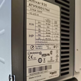
ATV 930 D37 N4
- ATV: Präfix für Altivar-Serie, Universelle Kennung für Schneider-Antriebe mit variabler Drehzahl
- 930: Standard-Unterserie der ATV900-Prozessreihe, als Allzweckantrieb für die Prozessindustrie positioniert, Unterstützung der asynchronen und synchronen Motorsteuerung
- D37: Leistungsbewertungscode; Passend für 37-kW-Motoren im Normalbetrieb und 30-kW-Motoren im Schwerlastbetrieb
- N4: Spannungs- und Konfigurationsklasse, Stellt einen dreiphasigen 380-480-V-Wechselstromeingang dar, 50/60Hz, eingebauter EMV-Filter der Klasse C2 und serienmäßig integrierter Brems-Chopper
Erweiterte Erläuterung der vollständigen Modellsuffixe
Ein typischer vollständiger Bestellcode ist „ATV930D37N4Z“.. Zusatzbuchstaben weisen auf zusätzliche Konfigurationen hin:
Kein Suffix: Standardgerät mit chinesischem Grafikdisplay und integrierter Bremseinheit
Z: Kostenoptimierte Version mit vereinfachtem Bedienfeld
Spezifische Buchstabensuffixe entsprechen der dedizierten Firmware (für Pumpe, Lüfter- und Krananwendungen)
- Grundlegende technische Spezifikationen
- Elektrische Leistungsparameter
| Parameterelement | Spezifikationswert | Bemerkungen |
| Nenneingangsspannung | 3-Phase 380~480V AC, -15%~+10 %, 50/60Hz±5 % | Anpassbar an Weitspannungsnetze |
| Nennausgangsleistung (Normaler Dienst) | 37kW (50PS) | Für variables Drehmoment / leichte Anwendungen mit konstantem Drehmoment |
| Nennausgangsleistung (Robust) | 30kW (40PS) | Für schwere Anwendungen mit konstantem Drehmoment und Stoßbelastung |
| Nennausgangsstrom (Normaler Dienst) | 74.5A (4kHz-Schaltfrequenz) | Nennwert unter 400-V-Netz |
| Nennausgangsstrom (Robust) | 61.5A (4kHz-Schaltfrequenz) | Nennwert unter 400-V-Netz |
| Überlastfähigkeit | Normaler Dienst: 120% Nennstrom für 60s | Zykluslänge: 10 Minuten |
| Robust: 150% Nennstrom für 2s | ||
| Ausgangsfrequenzbereich | 0.01Hz ~ 599Hz | Einstellbar über Parametereinstellungen |
| Steuermodi | V/F-Steuerung, sensorlose Vektorregelung, Vektorregelung mit geschlossenem Regelkreis (Encoder optional), Synchronmotorsteuerung | Kompatibel mit asynchron, Permanentmagnet-Synchron (PMSM) und synchrone Zurückhaltung (SynRM) Motoren |
| Ultimative Kurzschlussausschaltkapazität | Passend mit 125A-Sicherung, Hält einem Kurzschlussstrom von 50 kA stand | Koordinierungswert für den Upstream-Schutz |
| Integrierte Funktionen | Brems-Chopper-Einheit, EMV-Filter der Klasse C2, PID-Regler, STO-Sicherheitsfunktion | Standardintegration, Es sind keine zusätzlichen Optionen erforderlich |
- Mechanisch & Physikalische Parameter
Gesamtabmessungen (B × H × T): 271mm × 673 mm × 226 mm
Gesamtgewicht: Ca. 28.2kg
Gehäusebewertung: IP21 (IEC 60529) / UL-Typ 1, Schrankwandmontage
Kühlmethode: Zwangsluftkühlung mit intelligenten, temperaturgeregelten Lüftern mit variabler Drehzahl
Montageart: Vertikale Wandmontage, zulässige Neigung ±10°
Umgebungstemperatur im Betrieb: -15℃ ~ +50℃ (kein Derating); Leistungsreduzierung für +50℃~+60℃ erforderlich
III. Kernfunktionen & Technische Merkmale
- Motorsteuerungsleistung
Universal drive support for asynchronous motors, Permanentmagnet-Synchronmotoren (PMSM) and Synchronous Reluctance Motors (SynRM) without hardware replacement
Delivers 180% rated torque at 0.5Hz under sensorless vector mode for stable low-speed torque output
Standard motor auto-tuning function to automatically identify motor parameters and optimize control accuracy
Adjustable switching frequency from 2kHz to 16kHz to balance heat generation and motor noise
- Dedicated Process Industry Functions
Built-in high-precision PID regulator supporting closed-loop control of pressure, fließen, liquid level and temperature without external PLC
Multi-pump control function supporting up to 4 pumps for cyclic start/stop, fault switching and sleep/wake-up, suitable for constant-pressure water supply systems
Native flow compensation, sleep/wake and auto energy-saving modes, Bietet umfassende Energieeinsparungen von 20 bis 40 % für Lüfter- und Pumpenanwendungen
Integrierte Fehleraufzeichnung und Datenprotokollspeicherung für den neuesten Stand 10 Fehleraufzeichnungen und Betriebswellenformen zur Erleichterung der Rückverfolgbarkeitsanalyse
- Sicherheit & Schutzfunktionen
Standard-STO (Sicher abgeschaltetes Drehmoment) Funktion, die PL erreicht e / SIL 3 Sicherheitsniveau zur Einhaltung der Maschinensicherheitsanforderungen
Vollständiger elektrischer Schutz: Überstrom, Überspannung, Unterspannung, Kurzschluss am Ausgang, Erdschluss, Überhitzung des Motors, Überhitzung des Laufwerks, Verlust der Ausgangsphase
Unterstützung des Motorwärmeschutzmodells als Alternative zu externen Thermorelais für präzisen Motortemperaturschutz
- Kommunikation & Erweiterungsmöglichkeiten
Standard-Kommunikationsschnittstellen: Modbus RTU (RS485), CANopen
Erweiterbare industrielle Feldbusse: Profinet, EtherNet/IP, EtherCAT, Profibus DP, BACnet/IP, usw.
3 reservierte Erweiterungssteckplätze für I/O-Module, Encoder-Schnittstellenmodule und Kommunikationsmodule
Integrierter Webserver zur Unterstützung der Fernüberwachung, Parameterkonfiguration und Fehlerdiagnose über Webseiten
- Installation, Verdrahtung & Unterstützende Auswahl
- Main Circuit Cable Specifications (Copper Cable Reference)
Input power cable: Recommended 25mm² copper power cable
Output motor cable: Recommended 25mm² copper power cable; output reactor advised for long-distance wiring
Recommended braking resistor: Matched for 37kW model, 15Ω resistance with 5kW power rating
- Installation & Vorsichtsmaßnahmen bei der Verkabelung
- Vertikale Montage; reserve a minimum 100mm ventilation gap top and bottom, and 50mm clearance on left and right sides
- Separate power cables and control cables with a spacing ≥200mm to avoid electromagnetic interference
- Reliable earthing of ground terminals with earthing resistance ≤4Ω; single-end grounding for cable shields
- Anzugsdrehmoment der Klemmen: 12~15N·m for main circuit terminals, 0.6~0.8N·m for control circuit terminals
- Common Fault Handling Matrix
| Fehlercode | Fehlerphänomen | Ursachenanalyse | Schritt-für-Schritt-Lösungen |
| OHF | Drive trips with overheating alarm | 1. Damaged cooling fan / verstopfter Luftkanal | 1. Inspect fan operation and clear dust from air ducts |
| 2. Zu hohe Umgebungstemperatur | 2. Verbessern Sie die Belüftung des Schranks; Betrieb unter Leistungsminderung bei hohen Temperaturen | ||
| 3. Langfristiger Überlastbetrieb | 3. Laststrom prüfen und Überlastparameter anpassen | ||
| 4. Zu hohe Schaltfrequenzeinstellung | 4. Verringern Sie die Schaltfrequenz entsprechend | ||
| SCF1 / SCF3 | Motorkurzschluss / Erdkurzschlussfehler | 1. Beschädigte Isolierung der Ausgangskabel mit Phase-Erde-Leckstrom | 1. Unterbrechen Sie die Stromversorgung und trennen Sie die Motorkabel; Messen Sie den Isolationswiderstand von Kabeln und Motor |
| 2. Motorwicklungen kurzgeschlossen / Kurzschluss zwischen den Windungen | 2. Überprüfen Sie die Motorklemmen und den Klemmenkasten auf eindringendes Wasser oder Brandflecken | ||
| 3. Lose Anschlüsse mit Kupferdrahtgraten, die zu Kurzschlüssen führen | 3. Überprüfen Sie, ob die Motorparameter mit dem Typenschild übereinstimmen, und führen Sie das Autotuning erneut durch | ||
| OCF | Überstromauslösung während des Betriebs | 1. Zu kurze Beschleunigungszeit führt zu großem Anlaufstrom | 1. Extend acceleration time parameters and reduce startup torque boost value |
| 2. Sudden load variation or mechanical jamming | 2. Rotate motor by hand to check mechanical load and bearing jamming | ||
| 3. Malfunction of current detection components | 3. Disconnect load for no-load testing to troubleshoot hardware detection circuits | ||
| OVF | Overvoltage trip during deceleration | 1. Too short deceleration time and high load inertia | 1. Extend deceleration time and enable DC braking function |
| 2. Mismatched braking resistor resistance / lose Verkabelung | 2. Check braking resistor resistance and wiring; confirm braking unit is activated | ||
| 3. Zu hohe Netzspannung | 3. Monitor grid voltage; install input reactor if necessary | ||
| LF | Output phase loss alarm | 1. Open circuit on one phase of motor cable | 1. Test continuity of three phases of motor cable |
| 2. Poor contact from loose output terminals | 2. Tighten output terminals to specified torque | ||
| 3. Stromunsymmetrie durch einphasige Last | 3. Deaktivieren Sie die Phasenausfallerkennung vorübergehend nur für die Inbetriebnahme einer einphasigen Last (Wiederherstellung für den formellen Betrieb) | ||
| Leeres Bedienfeld ohne Display nach dem Einschalten | Das Bedienfeld bleibt nach dem Einschalten dunkel und reagiert nicht | 1. Phasenausfall der Eingangsleistung / zu niedrige Spannung | 1. Messen Sie die dreiphasige Eingangsspannung auf normale Werte |
| 2. Interner Schaltnetzteilfehler | 2. Unterbrechen Sie die Stromversorgung und stecken Sie das Anschlusskabel des Bedienfelds wieder ein | ||
| 3. Loses Bedienfeldkabel verursacht schlechten Kontakt | 3. Fehlerbehebung bei internen Gleichrichter- und Schaltnetzteilschaltungen |
- Leistungsmodellvergleich für die gleiche Serie (ATV930 N4-Serie, 380-480V)
| Modell | Normale Leistung | Hochleistungsleistung | Nennausgangsstrom (Normaler Dienst) |
| ATV930D15N4 | 15kW | 11kW | 30.4A |
| ATV930D22N4 | 22kW | 18.5kW | 41.5A |
| ATV930D30N4 | 30kW | 22kW | 54.8A |
| ATV930D37N4 | 37kW | 30kW | 74.5A |
| ATV930D45N4 | 45kW | 37kW | 87A |
| ATV930D55N4 | 55kW | 45kW | 108A |
VII. Markenübergreifende, gleichwertige Ersatzreferenz
| Marke | Äquivalentes Modell | Nennleistung | Beschreibung des Hauptunterschieds |
| ABB | ACS880-01-072A-3 | 37kW | Vergleichbare funktionale Positionierung; unterschiedliche Einbaumaße und Parameterarchitekturen |
| Siemens | 6SL3210-1PE27-5UL0 (G120) | 37kW | Modularer Aufbau mit separater Leistungs- und Steuereinheit; unterschiedliche Schrankkompatibilität |
| Innovation | MD500T37G | 37kW | Kostengünstige inländische Alternative, die gängige Funktionen abdeckt; nicht austauschbare Einbaumaße |
Häufige Fehler & Fehlerbehebungslösungen für Schneider ATV930D37N4
Als Antrieb in technischer Qualität aus der Altivar Process-Reihe von Schneider, Vor-Ort-Fehler des ATV930D37N4 lassen sich hauptsächlich in vier Kategorien einteilen: Lastanpassung, Schwankungen der Netzspannung, Wärmeableitungsbedingungen und Parameterkonfiguration. Die inhärente Hardware-Ausfallrate des Geräts selbst ist gering. Nachfolgend finden Sie eine vollständige Zusammenfassung häufiger Fehler vor Ort, einschließlich offizieller Standard-Fehlercodes, Fehlerphänomene, Ursachenanalyse und schrittweise Lösungsverfahren, zusammengestellt gemäß den offiziellen technischen Spezifikationen und Wartungspraktiken von Schneider.
- Allgemeine Fehlerbehebungsmatrix für Hochfrequenzfehler
- Überstrom & Kurzschlussfehler (Am häufigsten vor Ort; Zuerst die Prüfung des Hochspannungsstromkreises)
| Fehlercode | Fehlerphänomen | Ursachenanalyse | Schritt-für-Schritt-Lösungen |
| SCF1 | Sofortige Auslösung beim Start oder Betrieb mit Motorkurzschlussmeldung auf dem Bedienfeld | 1. Beschädigte Isolierung der Ausgangskabel, was zu einem Kurzschluss zwischen den Phasen führt | 1. Führen Sie NICHT wiederholt einen Reset durch und erzwingen Sie den Start; Unterbrechen Sie die Stromversorgung und trennen Sie die motorseitigen Kabel |
| Phase-Phase-Kurzschluss des Motors | 2. Windungskurzschluss der Motorwicklungen und durchgebrannter Klemmenkasten | 2. Messen Sie den Isolationswiderstand von Phase zu Phase und Phase zu Erde von U/V/W mit einem Megaohmmeter; Normalwert ≥5MΩ | |
| 3. Lose Anschlüsse mit Kupfergraten, die Lichtbögen zwischen den Phasen verursachen | 3. Überprüfen Sie den Klemmenkasten und die Klemmenleiste des Motors auf Brandflecken und Kurzschlüsse durch Kupferreste | ||
| 4. Mismatched motor parameters and control mode resulting in excessive startup inrush | 4. Verify motor nameplate parameters, re-run motor auto-tuning and reduce torque boost magnitude | ||
| 5. If false alarms persist with normal insulation, lower switching frequency to 2~4kHz appropriately | |||
| SCF3 | Earth fault trip immediately after power-on startup with abnormal output earth detection | 1. Single-phase earth damage on output cables | 1. Disconnect motor cables and measure insulation of cables and motor to earth separately |
| Motor Earth Short Circuit | 2. Breakdown of motor winding insulation to earth | 2. Install output reactor for long-distance wiring to suppress earth leakage current | |
| 3. Excessive leakage current due to large distributed capacitance of long cables | 3. Appropriately raise earth fault detection threshold for multi-motor parallel applications | ||
| 4. Der Gesamtleckstrom überschreitet den Schwellenwert, wenn mehrere Motoren parallel geschaltet sind | 4. Bestätigen Sie ein standardisiertes Erdungssystem mit zuverlässiger gemeinsamer Erdung für Antrieb und Motor | ||
| OCF | Auslösung bei plötzlicher Lastschwankung, wobei der Dauerstrom den Nennwert überschreitet | 1. Plötzliches Blockieren der mechanischen Last oder blockierte Lager | 1. Unterbrechen Sie die Stromversorgung und drehen Sie den Motor von Hand, um die Leichtgängigkeit des Motors zu prüfen und die mechanische Übertragung zu belasten |
| Überstrom während des Betriebs | 2. Eine zu kurze Beschleunigungszeit führt dazu, dass der Anlaufstrom den Nennwert überschreitet | 2. Erweitern Sie die Beschleunigungszeitparameter und reduzieren Sie den Koeffizienten für die Anlaufdrehmomenterhöhung | |
| 3. Nicht übereinstimmende Vektorsteuerungsparameter führen zu Stromschleifenschwingungen | 3. Führen Sie die automatische Abstimmung des statischen/dynamischen Motors erneut durch, um die Steuerparameter zu korrigieren | ||
| 4. Überprüfen Sie die Lastleistung und bestätigen Sie, ob für Hochleistungsanwendungen ein unterdimensioniertes Modell ausgewählt wurde |
- Überspannung, Unterspannung & Bremsstörungen
| Fehlercode | Fehlerphänomen | Ursachenanalyse | Schritt-für-Schritt-Lösungen |
| OVF | Häufige Auslösungen beim Abbremsen und Herunterfahren, wenn die Busspannung 780 V übersteigt | 1. Zu kurze Verzögerungszeit, hohe Lastträgheit und schnelle Energierückführung | 1. Verlängern Sie die Verzögerungszeit und aktivieren Sie die Gleichstrombremsfunktion für die Hilfsverzögerung |
| DC-Bus-Überspannung | 2. Die integrierte Bremseinheit ist deaktiviert oder der Widerstand/die Leistung des Bremswiderstands stimmt nicht überein | 2. Bestätigen Sie, dass die Parameter der Bremseinheit aktiviert sind, und überprüfen Sie den Widerstand des Bremswiderstands (15/5kW empfohlen für das 37-kW-Modell) | |
| 3. Eine zu hohe Netzeingangsspannung erhöht die Basis-Busspannung | 3. Überprüfen Sie, ob die Verkabelung des Bremswiderstands locker ist, und messen Sie den Widerstand auf normale Werte | ||
| 4. Überwachen Sie die Netzeingangsspannung; Installieren Sie eine Eingangsdrossel, wenn die Spannung zu hoch ist | |||
| USF | Abschaltung bei Netzschwankungen mit Busspannung unter dem Schwellenwert | 1. Veraltete Kontakte vorgeschalteter Leistungsschalter und Schütze verursachen großen Kontaktspannungsabfall | 1. Messen Sie die dreiphasige Eingangsspannung, um festzustellen, ob sie unter 320 V fällt (380V-System) |
| Eingangsunterspannung | 2. Einbruch der Netzspannung und Spannungsabfall durch gleichzeitiges Anlaufen von Geräten mit großer Kapazität | 2. Überprüfen Sie das Anzugsdrehmoment der Eingangsklemmen und prüfen Sie die Oxidation der vorgeschalteten Schaltkontakte | |
| 3. Beschädigte interne Gleichrichterbrücke oder verminderte Kapazität des Buskondensators | 3. Wenn der Alarm bei konstanter Normalspannung weiterhin besteht, Messen Sie die DC-Busspannung und beheben Sie Fehler in Gleichrichter- und Kondensatorschaltungen | ||
| NLP | Auf dem Bedienfeld leuchtet nur die Kontrollanzeige, es wird keine Spannung im Hauptstromkreis angezeigt | 1. Nur 24-V-Steuerspannung angeschlossen, ohne bestromten dreiphasigen Hauptstromkreis | 1. Überprüfen Sie den Stromversorgungsstatus der dreiphasigen R/S/T-Hauptstromversorgung |
| Keine Hauptstromversorgung | 2. Phase loss on main circuit incoming lines or blown fuses | 2. Measure DC bus voltage between PA/+ and PC/- Terminals; nominal value approx. 540V (380V-Eingang) | |
| 3. Malfunction of internal voltage detection circuit | 3. If alarm persists with normal bus voltage, internal detection hardware failure requiring after-sales maintenance | ||
| BRF | Trip during braking with abnormal braking circuit prompt | 1. Short-circuited braking resistor or excessive resistance deviation | 1. Cut power and measure braking resistor resistance to match nominal value |
| Braking Unit Fault | 2. Damaged built-in braking chopper IGBT | 2. Inspect braking resistor wiring for short circuits and loose connections | |
| 3. Excessively high braking current limit setting | 3. Replace braking unit or complete drive for hardware damage |
- Überhitzung & Overload Faults
| Fehlercode | Fehlerphänomen | Ursachenanalyse | Schritt-für-Schritt-Lösungen |
| OHF | Trip after a period of operation with heatsink temperature exceeding threshold | 1. Damaged cooling fan with insufficient speed and dust-blocked air ducts | 1. Inspect fan operation and clear dust from air ducts and heatsink |
| Drive Overheating | 2. Poor cabinet ventilation and ambient temperature over 50℃ | 2. Improve cabinet ventilation by installing cooling fans; operate under derating factor at high temperatures | |
| 3. Long-term overload operation and excessively high switching frequency setting | 3. Appropriately lower switching frequency to reduce module heat generation | ||
| 4. Poor contact between heatsink and power modules | 4. Allow temperature to drop naturally after fault clearance; restart via manual or auto reset | ||
| OLF | Motor overload prompt during operation with trip following inverse time curve | 1. Excessive load with continuous operating current exceeding motor rated value | 1. Monitor actual operating current and verify matching between load and motor power |
| Motorüberlastung | 2. Overly sensitive motor thermal protection parameter settings | 2. Adjust motor thermal protection curve to adapt to actual working conditions | |
| 3. Rising current caused by poor motor cooling and worn bearings | 3. Inspect motor cooling fan and bearing conditions to eliminate motor body faults | ||
| OTF | Shutdown triggered by external temperature sensor | 1. Excessive actual motor temperature rise and failed cooling system | 1. Inspect motor cooling system for blocked air ducts and damaged fans |
| Überhitzung des Motors (PTC) | 2. Open or short-circuited PTC sensor wiring | 2. Measure resistance at PTC terminals to confirm intact sensor and wiring | |
| 3. Mismatched sensor type and parameter settings | 3. Verify matching between temperature protection parameter settings and sensor model |
- Motorsteuerung & Load Faults
| Fehlercode | Fehlerphänomen | Ursachenanalyse | Schritt-für-Schritt-Lösungen |
| LF | Output phase loss alarm during startup or operation with severe three-phase current unbalance | 1. Open circuit on one phase of output cables and loose detached terminals | 1. Test continuity of three phases of motor cables and tighten output terminals |
| Verlust der Ausgangsphase | 2. Open circuit on one phase of motor windings | 2. Measure resistance of three-phase motor windings to rule out open circuits | |
| 3. Excessive current deviation caused by single-phase or special loads | 3. Temporarily disable phase loss detection only for special load commissioning; Wiederherstellung für den formellen Betrieb | ||
| STF | Trip during low-speed operation with sustained high current | 1. Locked mechanical load and foreign object jamming transmission mechanism | 1. Cut power and rotate equipment by hand to locate mechanical jamming points and clean transmission mechanisms |
| Motor Stall | 2. Überempfindliche Strom- und Zeitparameter des Blockierschutzes | 2. Überprüfen Sie die Stallschutzparameter und lockern Sie die Stallstrom- und Zeitschwellen entsprechend | |
| 3. Das Drehmoment reicht nicht aus, um schwere Anlauflasten anzutreiben | 3. Erhöhen Sie den Wert der Drehmomenterhöhung für hohe Anlauflasten oder wählen Sie ein Modell mit höherer Leistung | ||
| ANF | Abschaltung wegen zu großer Geschwindigkeitsabweichung im geschlossenen Regelkreis | 1. Falsche Geberverkabelung, Signalstörungen und abnormales Feedback | 1. Überprüfen Sie die Verkabelung des Encoders und die Schirmerdung, um Störungen zu beseitigen |
| Verlust der Ladungsverfolgung | 2. Eine zu hohe oder niedrige Schleifenverstärkung führt zu Systemschwingungen / langsame Reaktion | 2. Passen Sie die Verstärkung des Geschwindigkeitsregelkreises und die Integralzeit an, um die Steuerparameter zu optimieren | |
| 3. Zu hohe Lastträgheit und unzureichende Bremsleistung | 3. Installieren Sie einen Bremswiderstand für Lasten mit hoher Trägheit und verlängern Sie die Beschleunigungs-/Verzögerungszeit | ||
| 4. Deaktivieren Sie vorübergehend die Lastverfolgungserkennungsfunktion für nicht kritische Anwendungen |
- Kommunikation, Parameter & Konfigurationsfehler
| Fehlercode | Fehlerphänomen | Ursachenanalyse | Schritt-für-Schritt-Lösungen |
| ILF | Nicht erkennbare Erweiterungsmodule (Encoder, Kommunikationskarten) | 1. Lockerer Einschub und schlechter Kontakt der Optionskarten | 1. Unterbrechen Sie die Stromversorgung und stecken Sie die Optionskarten wieder ein, um sicherzustellen, dass die Stifte vollständig sitzen und nicht oxidiert sind |
| Interner Kommunikationsfehler der Optionskarte | 2. Inkompatibles Modulmodell mit Laufwerk | 2. Überprüfen Sie die Kompatibilität des Modulmodells mit der ATV930-Serie | |
| 3. Kommunikationsunterbrechung durch elektromagnetische Störungen | 3. Verstärken Sie die Schirmerdung und verlegen Sie die Kabel entfernt von Stromleitungen | ||
| CFF | Alarm nach Hardware-Austausch mit nicht übereinstimmenden Parametern und Hardware | 1. Die Konfiguration wurde nach dem Austausch von Optionskarten oder Leistungsplatinen nicht aktualisiert | 1. Rufen Sie das Konfigurationsmenü auf und führen Sie die automatische Hardware-Identifizierung durch |
| Konfigurationskonflikt | 2. Inkompatible Firmware-Version und Hardware | 2. Aktualisieren Sie die Laufwerks-Firmware auf die entsprechende Version | |
| 3. Versionskonflikt während der Wiederherstellung der Parametersicherung | 3. Werkseinstellungen wiederherstellen und Parameter neu konfigurieren | ||
| EEF1/EEF2 | Parameter können nicht gespeichert werden und gehen nach dem Einschalten verloren | 1. Beschädigte Daten auf dem EEPROM-Speicherchip | 1. Werkseinstellungen wiederherstellen und Parameter neu eingeben |
| Speicherfehler | 2. Datenstörung durch häufige Stromausfälle und Spannungsspitzen | 2. Ersetzen Sie die Steuerplatine, wenn der Fehler aufgrund beschädigter Speicherchip-Hardware wiederholt auftritt |
- Stromversorgung & Hardwarefehler
| Fehlerphänomen | Ursachenanalyse | Schritt-für-Schritt-Lösungen |
| Leeres Bedienfeld ohne Display nach dem Einschalten | 1. Phasenausfall im Hauptstromkreis und durchgebrannte Eingangssicherungen | 1. Messen Sie die dreiphasige Eingangsspannung, um sicherzustellen, dass an den eingehenden Leitungen kein Phasenverlust oder kein offener Stromkreis vorliegt |
| 2. Beschädigtes internes Schaltnetzteil | 2. Unterbrechen Sie die Stromversorgung und stecken Sie das Anschlusskabel des Bedienfelds wieder ein; Test mit Ersatzpanel | |
| 3. Loses Bedienfeldkabel und defektes Bedienfeld selbst | 3. Bei Ausfall des internen Schaltnetzteils bei normaler Busspannung ist eine professionelle Wartung erforderlich | |
| Der vorgeschaltete Leistungsschalter löst sofort nach dem Einschalten aus | 1. Eingangsseitiger Kurzschluss und Ausfall der Gleichrichterbrücke | 1. Schalten Sie das Gerät NICHT wiederholt ein; Unterbrechen Sie die Stromversorgung und messen Sie die eingangsseitige Isolierung und den IGBT-Durchgang |
| 2. Kurzschlussschäden an IGBT-Leistungsmodulen | 2. Gleichrichterbrücke prüfen, Buskondensatoren und IGBT-Module auf Durchschlagsschäden | |
| 3. Kurzschlussausfall der Buskondensatoren | 3. Schicken Sie das komplette Gerät an das Werk zurück oder veranlassen Sie eine professionelle Wartung bei Schäden an der Stromversorgungshardware; Eine Demontage von Stromkreisen vor Ort ist untersagt |
- Allgemeine Verfahren zur Fehlerbehebung (Schnelle Ortung vor Ort)
- Lesen Sie zuerst die Fehlercodes: Rufen Sie Fehlercodes und eingefrorene Daten einschließlich Strom ab, Spannung und Temperatur beim Auftreten eines Fehlers über das Panel-Diagnosemenü, um Fehlerkategorien schnell zu identifizieren.
- Überprüfen Sie zunächst die Hochspannungskreise: Für Überstrom, Kurzschluss- und Überspannungsfehler, Unterbrechen Sie die Stromversorgung, um externe Kabel zu überprüfen, Motoren und Stromnetze, bevor Sie den Antrieb selbst überprüfen.
- Parameterüberprüfung: Bei Fehlauslösungen und anormaler Regelleistung, Priorisieren Sie die Überprüfung von Kernkonfigurationen wie Motorparametern, Schutzschwellen und Beschleunigungs-/Verzögerungszeit; Führen Sie das Autotuning bei Bedarf erneut durch.
- Überprüfung des Hardwareaustauschs: Einführung von Ersatztests für das Panel, Kommunikations- und Optionskartenfehler, um schnell zwischen Gerätefehlern und Zubehördefekten zu unterscheiden.
III. Fehlervermeidung & Richtlinien zur routinemäßigen Wartung
- Reinigen Sie Luftkanäle und Kühlkörper vierteljährlich von Staub; Überprüfen Sie den Betrieb des Kühlventilators jährlich und tauschen Sie ihn bei ungewöhnlichen Geräuschen sofort aus.
- Ziehen Sie die Hochstromklemmen einmal jährlich mit dem Nenndrehmoment nach, um übermäßige Übergangswiderstände und Wärmeentwicklung zu vermeiden.
- Zur ersten Energetisierung nach längerer Lagerung, Bei niedriger Spannung vorheizen, um Schäden durch Stoßströme an den Buskondensatoren zu verhindern.
- Installieren Sie Eingangsdrosseln für Standorte mit starken Netzspannungsschwankungen; Einbau von Ausgangsdrosseln für die Motorverkabelung über große Entfernungen.
| ATV61H075N4Z | ATV61H075N4 | ATV71H075N4Z | ATV71H075N4 | ATV610U07N4 |
| ATV61HU15N4Z | ATV61HU15N4 | ATV71HU15N4Z | ATV71HU15N4 | ATV610U15N4 |
| ATV61HU22N4Z | ATV61HU22N4 | ATV71HU22N4Z | ATV71HU22N4 | ATV610U22N4 |
| ATV61HU30N4Z | ATV61HU30N4 | ATV71HU30N4Z | ATV71HU30N4 | ATV610U30N4 |
| ATV61HU40N4Z | ATV61HU40N4 | ATV71HU40N4Z | ATV71HU40N4 | ATV610U40N4 |
| ATV61HU55N4Z | ATV61HU55N4 | ATV71HU55N4Z | ATV71HU55N4 | ATV610U55N4 |
| ATV61HU75N4Z | ATV61HU75N4 | ATV71HU75N4Z | ATV71HU75N4 | ATV610U75N4 |
| ATV61HD11N4Z | ATV61HD11N4 | ATV71HD11N4Z | ATV71HD11N4 | ATV610D11N4 |
| ATV61HD15N4Z | ATV61HD15N4 | ATV71HD15N4Z | ATV71HD15N4 | ATV610D15N4 |
| ATV61HD18N4Z | ATV61HD18N4 | ATV71HD18N4Z | ATV71HD18N4 | ATV610D18N4 |
| ATV61HD22N4Z | ATV61HD22N4 | ATV71HD22N4Z | ATV71HD22N4 | ATV610D22N4 |
| ATV61HD30N4Z | ATV61HD30N4 | ATV71HD30N4Z | ATV71HD30N4 | ATV610D30N4 |
| ATV61HD37N4Z | ATV61HD37N4 | ATV71HD37N4Z | ATV71HD37N4 | ATV610D37N4 |
| ATV61HD45N4Z | ATV61HD45N4 | ATV71HD45N4Z | ATV71HD45N4 | ATV610D45N4 |
| ATV61HD55N4Z | ATV61HD55N4 | ATV71HD55N4Z | ATV71HD55N4 | ATV610D55N4 |
| ATV61HD75N4Z | ATV61HD75N4 | ATV71HD75N4Z | ATV71HD75N4 | ATV610D75N4 |
| ATV930U07N4 | ATV61HD90N4 | 90KW | ATV71HD90N4 | ATV610D90N4 |
| ATV930U15N4 | ATV61HC11N4 | 110KW | ATV71HC11N4 | ATV610C11N4 |
| ATV930U22N4 | ATV61HC13N4 | 130KW | ATV71HC13N4 | ATV610C13N4 |
| ATV930U30N4 | ATV61HC16N4 | 160KW | ATV71HC16N4 | ATV610C16N4 |
| ATV930U40N4 | ATV61HC22N4 | 220KW | ATV71HC22N4 | ATV610C22N4 |
| ATV930U55N4 | ATV61HC25N4 | 250KW | ATV71HC25N4 | ATV610C25N4 |
| ATV930U75N4 | ATV212H075N4 | ATV310H037N4A | ATV312H037N4 | ATV320U04N4B |
| ATV930D11N4 | ATV212HU15N4 | ATV310H055N4A | ATV312H055N4 | ATV320U06N4B |
| ATV930D15N4 | ATV212HU22N4 | ATV310H075N4A | ATV312H075N4 | ATV320U07N4B |
| ATV930D18N4 | ATV212HU30N4 | ATV310HU11N4A | ATV312HU11N4 | ATV320U11N4B |
| ATV930D22N4 | ATV212HU40N4 | ATV310HU15N4A | ATV312HU15N4 | ATV320U15N4B |
| ATV930D30N4 | ATV212HU55N4 | ATV310HU22N4A | ATV312HU22N4 | ATV320U22N4B |
| ATV930D37N4 | ATV212HU75N4 | ATV310HU30N4A | ATV312HU30N4 | ATV320U30N4B |
| ATV930D45N4 | ATV212HD11N4 | ATV310HU40N4A | ATV312HU40N4 | ATV320U40N4B |
| ATV930D55N4 | ATV212HD15N4 | ATV310HU55N4A | ATV312HU55N4 | ATV320U55N4B |
| ATV930D75N4 | ATV212HD18N4 | ATV310HU75N4A | ATV312HU75N4 | ATV320U75N4B |
| ATV930D90N4 | ATV212HD22N4 | ATV310HD11N4A | ATV312HD11N4 | ATV320D11N4B |
| ATV930C11N4 | ATV212HD30N4 | ATV310HD15N4A | ATV312HD15N4 | ATV320D15N4B |
| ATV930C13N4 | ATV212HD37N4 | ATV320U04N4C | ATV340D11N4E | ATV32HU11N4 |
| ATV930C16N4 | ATV212HD45N4 | ATV320U06N4C | ATV340D15N4E | ATV32HU15N4 |
| ATV930C22N4 | ATV212HD55N4 | ATV320U07N4C | ATV340D18N4E | ATV32HU22N4 |
| ATV930C25N4 | ATV212HD75N4 | ATV320U11N4C | ATV340D22N4E | ATV32HU30N4 |
| ATS22D17Q | ATS48D17Q | ATV320U15N4C | ATV340D30N4E | ATV32HU40N4 |
| ATS22D32Q | ATS48D32Q | ATV320U22N4C | ATV340D37N4E | ATV32HU55N4 |
| ATS22D47Q | ATS48D47Q | ATV320U30N4C | ATV340D45N4E | ATV32HU75N4 |
| ATS22D62Q | ATS48D62Q | ATV320U40N4C | ATV340D55N4E | ATV32HD11N4 |
| ATS22D75Q | ATS48D75Q | ATV320U55N4C | ATV340D75N4E | ATV32HD15N4 |
| ATS22D88Q | ATS48D88Q | ATV320U75N4C | ACS510-01-03A3-4 | ACS550-01-03A3-4 |
| ATS22C11Q | ATS48C11Q | ATV320D11N4C | ACS510-01-04A1-4 | ACS550-01-04A1-4 |
| ATS22C14Q | ATS48C14Q | ATV320D15N4C | ACS510-01-05A6-4 | ACS550-01-05A6-4 |
| ATS22C17Q | ATS48C17Q | ACS580-01-02A7-4 | ACS510-01-07A2-4 | ACS550-01-07A2-4 |
| ATS22C21Q | ATS48C21Q | ACS580-01-03A4-4 | ACS510-01-09A4-4 | ACS550-01-09A4-4 |
| ATS22C25Q | ATS48C25Q | ACS580-01-04A1-4 | ACS510-01-012A-4 | ACS550-01-012A-4 |
| ATS22C32Q | ATS48C32Q | ACS580-01-05A7-4 | ACS510-01-017A-4 | ACS550-01-017A-4 |
| ATS22C41Q | ATS48C41Q | ACS580-01-07A3-4 | ACS510-01-025A-4 | ACS550-01-025A-4 |
| ATS22C48Q | ATS48C48Q | ACS580-01-09A5-4 | ACS510-01-031A-4 | ACS550-01-031A-4 |
| ATS22C59Q | ATS48C59Q | ACS580-01-12A7-4 | ACS510-01-038A-4 | ACS550-01-038A-4 |
| ACS580-01-169A-4 | ATS48C66Q | ACS580-01-018A-4 | ACS510-01-046A-4 | ACS550-01-046A-4 |
| ACS580-01-206A-4 | ACS580-01-106A-4 | ACS580-01-026A-4 | ACS510-01-060A-4 | ACS550-01-060A-4 |
| ACS580-01-246A-4 | ACS580-01-145A-4 | ACS580-01-033A-4 | ACS510-01-072A-4 | ACS550-01-072A-4 |
| ACS580-01-293A-4 | ACS510-01-246A-4 | ACS580-01-039A-4 | ACS510-01-088A-4 | ACS550-01-088A-4 |
| ACS580-01-363A-4 | ACS510-01-290A-4 | ACS580-01-046A-4 | ACS510-01-125A-4 | ACS550-01-125A-4 |
| ACS580-01-430A-4 | ACS550-01-246A-4 | ACS580-01-062A-4 | ACS510-01-157A-4 | ACS550-01-157A-4 |
| ACS580-04-505A-4 | ACS550-01-290A-4 | ACS580-01-073A-4 | ACS510-01-180A-4 | ACS550-01-180A-4 |
| ACS580-04-585A-4 | ACS580-01-088A-4 | ACS510-01-195A-4 | ACS550-01-195A-4 |


 Impuls-Heißsiegel-Temperaturregler")


")


NH42-63-318x560.png "Automatische Transferschalter vom Typ CHINT PC (ATS)NH42-63/4SZ")


