 Schütz,Leistungsschalter,Sensor,Encoder,SPS,Konverter

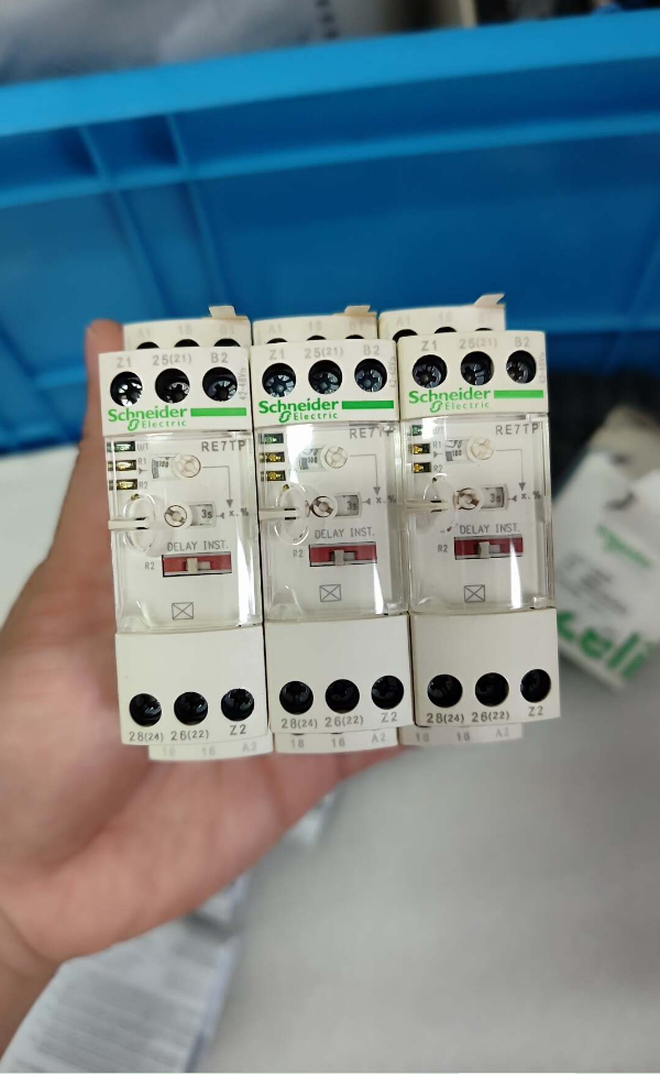

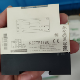
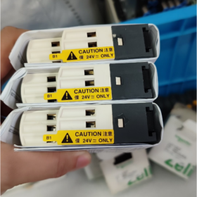
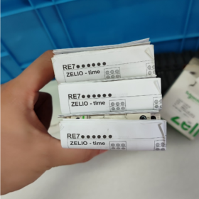
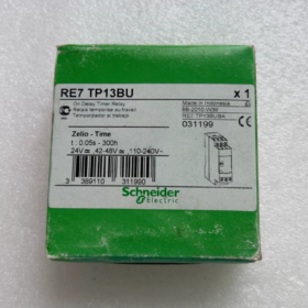
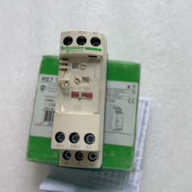
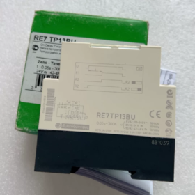
Serie: Gesuchte Zeit RE7 Zeitrelais; Status: Auslaufmodell (Die Produktion wurde im April eingestellt-02-2021)
Funktion: Einschaltverzögerung. Die Zeitmessung beginnt beim Einschalten; Kontakte werden aktiviert, nachdem die voreingestellte Verzögerung abgelaufen ist.
Modellbezeichnung
RE7: Zelio Time RE7 Zeitrelais-Serie
TP: T=Zeitpunkt, P=Einschaltverzögerung
13: 2 Wechslerkontakte (2CO)
B: Mehrspannungsversion (24 VAC/DC / 42-48 VAC/DC / 110-240 VAC drei Versorgungsbereiche)
U: Schraubklemmen, DIN-Schienenmontage
Wichtigste technische Spezifikationen
| Artikel | Parameter |
| Timing-Funktion | Einschaltverzögerung (Einschaltverzögerung) |
| Zeitbereich | 0.05 s … 300h, Bereichswahlschalter plus Potentiometer-Feinabstimmung |
| Versorgungsspannung | Drei Bereiche: 24 VAC/DC; 42-48VAC/DC; 110-240 VAC 50/60 Hz |
| Ausgangskontakte | 2CO (2 Umstellung, 2NO+2NC) |
| Thermischer Dauerstrom Ith | 8 A |
| AC-15 250V | 3 A |
| DC-13 24V | 2 A; DC-13 250V: 0.1 A |
| Timing-Genauigkeit | ±10 % des Skalenendwerts; Wiederholgenauigkeit ±0,2 % |
| Zeit zurücksetzen | 50 MS; minimaler Triggerimpuls 20ms |
| Modulbreite | 22.5 mm, DIN-Schienenmontage oder Schraubmontage |
| Terminals | Schraubentyp, Anzugsdrehmoment 0,6-1,1 N·m |
| Betriebstemperatur | -20℃ ~ +60℃ |
| Gewicht | Ca. 150 G |
Anschlussbelegung
A1-A2: 110-240 VAC-Stromversorgung
B1-A2: 24 VAC/DC-Stromversorgung
B2-A2: 42-48 VAC/DC-Stromversorgung
15-16-18: 1st Wechslerkontakt; 25-26-28: 2und Wechslerkontakt
⚠️ Keine galvanische Trennung zwischen Versorgungsstromkreis und Steuerstromkreis. Beachten Sie die Sicherheitsvorkehrungen für die Verkabelung.
Offizieller direkter Ersatz
RE22R2AMR (Harmony RE22-Serie). Pinbelegung und Abmessungen kompatibel, Einschaltverzögerungsfunktion, 2CO-Kontakte, Weitbereichsversorgung 24-240VAC/DC, Zeitbereich 0,05 s-300 h.
Ersatzhinweise
- RE22R2AMR ist mit identischer Verdrahtungslogik direkt auf der DIN-Schiene austauschbar.
- RE7TP13BU verfügt über eine Dreibereichsversorgung; RE22R2AMR verwendet eine einzelne Weitspannungsspannung von 24–240 VAC/DC ohne separate A1/B1/B2-Klemmen.
- Äquivalenter Zeitbereich, Kontaktwerte und 22,5 mm Breite.
- Für ältere Geräte, nur Lagerbestand / Gebrauchtgeräte sind verfügbar; Neue Projekte müssen RE22R2AMR übernehmen.
Checkliste für die Inspektion gebrauchter Geräte (Ersatzteilservice)
- Einschalttest: Legen Sie AC220V an A1-A2 an, Zeitbereichsschalter einstellen. Überprüfen Sie die zuverlässige Kontaktumschaltung nach Ablauf der Zeit, indem Sie den LED-Status beobachten.
- Verwenden Sie ein Multimeter, um den Durchgang beider Umschaltkontaktsätze zu prüfen; Bestätigen Sie, dass kein Kontaktschweißen vorliegt.
- Überprüfen Sie das Gehäuse und die Einstellknöpfe auf Risse; Überprüfen Sie die Anschlüsse auf Brandflecken.
- Timing kalibrieren: Testen Sie die Kurzzeitreichweite (zweite Skala) tatsächlicher Zeitfehler, um die Alterung der Zeitschaltkreise zu überprüfen.
Praktische Anwendungsfälle für Schneider RE7TP13BU Zeitrelais mit Einschaltverzögerung
Hauptmerkmale: Die Zeitmessung beginnt mit der Erregung der Spule, sofortiges Zurücksetzen nach Stromunterbrechung; 2CO-Umschaltkontakte; 0.05 s-300h großer Zeitbereich; Multispannungseingang 24/48/230V; Montage auf DIN-Schiene. Weit verbreitet in einfachen Schaltschränken ohne SPS, Nachrüstung von Altgeräten und kompletten Maschinen. Auslaufmodell; Ersatz für ein neues Projekt: RE22R2AMR.
Fall1: Stern-Dreieck-Motor mit reduzierter Spannung (Klassische Anwendung)
Industrie: Wasserpumpe, Schaltschränke für Luftkompressoren und Ventilatoren
Verdrahtung: Die Spule RE7TP13BU ist parallel zum Hauptschütz geschaltet. Der zeitgesteuerte Öffnerkontakt ist in Reihe in den Sternschützkreis geschaltet; Der zeitgesteuerte Schließerkontakt ist in Reihe in die Dreieckschützschaltung geschaltet.
Voreingestellte Verzögerung: 3-10 S, entsprechend der Motorleistung angepasst.
Bedienablauf:
- Beim Startbefehl, Hauptschütz und Schützeinzug in Sternschaltung; Motor startet in Sternschaltung. RE7TP13BU wird mit Strom versorgt und die Zeitmessung beginnt.
- Wenn die voreingestellte Zeit abgelaufen ist: Der zeitgesteuerte NC öffnet sich, um das Sternschütz abzuschalten; Zeitgesteuertes NO schließt, um das Dreieckschütz zu aktivieren. Motor schaltet auf Vollspannungs-Dreieckbetrieb um.
Auswahlvorteil: Doppelte 2CO-Kontakte dienen genau zum Unterbrechen des Sternstromkreises und zum Schließen des Dreieckstromkreises. Multispannungskompatibilität, passend für Schrank AC220V / AC24V-Steuerversorgungen.
Notiz: Implementieren Sie eine elektrische Verriegelung zwischen Stern- und Dreieckschützen, um einen Kurzschluss zu verhindern.
Fall2: Sequentielles Starten des Motors für die Produktionslinie (Reduzieren Sie den Einschaltstrom)
Industrie: Förderstrecken, Dosierausrüstung, Verpackungsmaschinenschränke
Erfordernis: Nach dem Einschalten des Systems, 1 Der Hauptfördermotor startet sofort; 2 Der Vorschubmotor startet nach einer Verzögerung von 5 Sekunden; 3 Der Entlademotor startet nach weiteren 8 Sekunden Verzögerung, Vermeidung gleichzeitiger starker Einschaltströme in das Stromnetz.
Durchführung: Zwei RE7TP13BU-Einheiten. Das globale Startsignal aktiviert beide Timerspulen gleichzeitig.
Einheit1 auf 5s eingestellt: Kontakt schließt, um zu starten 2 Motor nach Zeitüberschreitung.
Einheit2 auf 13s eingestellt: Kontakt schließt, um zu starten 3 Motor nach Zeitüberschreitung.
Ausstattungsvorteile: Hohe Genauigkeit für kurze Verzögerungen ab 0,05 s; Kompakte 22,5-mm-DIN-Schienen-Grundfläche, die Platz im Schrank spart; unterstützt die 24-VDC-Steuerung für ältere DC-Bedienfelder.
Fall3: Einschaltverzögerungsschutz für HVAC-Kompressoren
Industrie: Zentrale Klimaanlagen, luftgekühlte Kühlschränke
Prozessanforderung: Der Kompressor darf nicht sofort nach dem Einschalten des Geräts starten. Eine Wartezeit von 3–5 Minuten ermöglicht den Druckausgleich des Kältemittels und verhindert Schäden am Kompressor durch Flüssigkeitsschläge. Kühlgebläse läuft direkt.
Logik: Beim Einschalten der Hauptstromversorgung, Das Kühlgebläseschütz wird direkt aktiviert. Die RE7TP13BU-Spule wird gleichzeitig mit Strom versorgt und beginnt mit der Zeitmessung. Nach Ablauf der Verzögerung, Der Kontakt schließt sich, um das Kompressorschütz zu betätigen. Der Timer wird nach einem Stromausfall automatisch zurückgesetzt, um beim nächsten Start ein neues Timing zu gewährleisten.
Auswahl-Highlight: Der Vollbereich bis 300 Stunden deckt Minuten- und Stundenbereichseinstellungen ab; Breiter Temperaturbereich -20 bis +60 °C, geeignet für hohe Umgebungstemperaturen im Schaltschrank.
Fall4: Einschalt-Vorheizverzögerungsausgang für Heizgeräte (Öfen)
Industrie: Kleine Wärmebehandlungsöfen, Härtungsöfen
Erfordernis: Heizelemente werden sofort aktiviert. Nach Ablauf der voreingestellten Garraum-Vorheizzeit, Das Ausgangssignal ermöglicht die Freigabe der Türöffnung oder aktiviert das Förderband für den Materialaustrag.
Logik: Durch das Schließen des Hauptgeräteschalters werden die Heizgeräte direkt eingeschaltet. Die RE7TP13BU-Spule wird mit Strom versorgt, um die Zeitmessung zu starten. Nach Ablauf der Zeitmessung, Umschaltkontakte schalten um, um dem nachgeschalteten Schütz ein Bereitschaftssignal zu geben / Anzeigelampe.
Erläuterung: Ein Schließerkontakt fungiert als Bereitschaftssignal „Vorheizen abgeschlossen“.; Der komplementäre NC-Kontakt bietet eine Verriegelung, um die Ausgabe während der Vorheizphase zu sperren.
Fall5: Einschalt-Entprellung zur Steuerung der Pumpstation (Unterdrücken Sie unerwünschte Alarme)
Industrie: Schaltschränke für die Wasserversorgung und -entsorgung
Problem: Unmittelbar nach dem Einschalten des Schranks sind die Signale des Füllstandsensors für kurze Zeit instabil, Fehlalarme auslösen.
Lösung: Die Einschaltverzögerung des RE7TP13BU ist beim Einschalten des Systems auf 2–3 Sekunden eingestellt. Der Alarmkreis wird erst nach Ablauf der Zeit aktiviert. Vorübergehende Einschaltspitzen werden gefiltert; Nur stabilisierte Füllstandssensorsignale können Alarme auslösen.
Fall6: Verzögerung der Bestätigung der Schutztür für komplette Maschinen
Industrie: Kleine Werkzeugmaschinen, automatisierte Werkzeugvorrichtungen
Logik: Wenn die Schutztür vollständig geschlossen ist, Der Tor-Endschalter aktiviert die RE7TP13BU-Spule. Eine Verzögerung von 0,5–1 s bestätigt die zuverlässige Torverriegelung; Anschließend schließen sich die Kontakte, um die Bewegung der Maschine zu ermöglichen, Verhinderung von Fehlstarts, die durch das Abprallen des Gate-Kontakts verursacht werden.
Betriebshinweise & Häufige Fallstricke im Feldeinsatz für RE7TP13BU
- Einschaltverzögerungscharakteristik: Die Abschaltung der Spule löst einen sofortigen vollständigen Reset und eine Freigabe der Zeitsteuerung aus. Ausschaltverzögerungsfunktionen können nicht ausgeführt werden; Wählen Sie die RE7RP-Serie für die Ausschaltverzögerung.
- Unterscheidung der Stromversorgungsklemmen: A1-A2 =110-240VAC; B1-A2 =24VAC/DC; B2-A2 =42-48VAC/DC. Ein falscher Anschluss der Klemmen führt zur Zerstörung der internen Elektronik.
- Kontaktkapazität: AC-15 250 V Nennstrom maximal 3 A. Betreiben Sie große Schützspulen nicht direkt; Zwischenrelais als Puffer verwenden.
- Ersatzteilaustausch: Für ausgefallenes RE7TP13BU in älteren Schränken, durch RE22R2AMR ersetzen. RE22 verwendet eine einzelne Weitspannungsspannung von 24–240 VAC/DC ohne B1/B2-Klemmen; Kleinere schematische Modifikation erforderlich.
Funktionsprinzip des Einschaltverzögerungszeitrelais RE7TP13BU von Schneider
RE7TP13BU ist ein analog-elektronisches Zeitrelais mit Einschaltverzögerung. Es verfügt über keinen Mikrocontroller / SPS-Chip und implementiert das Timing mittels RC-Lade-Entlade-Schaltung, DIN-Schienenmontage, ausgestattet mit 2 Umstellung (2CO) Kontakte.
Kernlogik: Die Zeitmessung beginnt erst, wenn die Spule mit Strom versorgt wird. Kontakte bleiben vor dem Timeout im Originalzustand. Ausgangskontakte schalten nach Abschluss der Zeitmessung um. Vollständiges sofortiges Zurücksetzen und Löschen des Timings bei Abschalten der Spule.
Interne Funktionsblöcke
- Mehrspannungsnetzteil: Akzeptiert drei Versorgungsbereiche (24 VAC/DC, 42-48 VAC/DC, 110-240 VAC), Wandelt externe Steuerspannung in Niederspannungs-Arbeitsspannung für interne elektronische Schaltkreise um.
- RC-Zeitschaltung: Der Bereichswahlschalter wählt die Zeitspanne aus; Potentiometer führt die Feineinstellung durch; Die Zeitsteuerung erfolgt über die Aufladung des Kondensators.
- Komparator-Treiberschaltung: Überwacht die Kondensatorspannung. Wenn die Ladespannung den Schwellenwert erreicht, es betätigt das Ausgangsrelais.
- Ausgangsausführungsrelais: Zwei Wechslerkontaktsätze (15-16-18 / 25-26-28), Passiver Trockenkontaktschalter für externen Signalausgang.
- Status-LED-Anzeige: Leuchtet im eingeschalteten Zustand konstant. Die LED zeigt nicht an, dass die Zeitmessung abgeschlossen ist (Die LED der RE7-Serie zeigt nur das Vorhandensein der Stromversorgung an).
Vollständiger Betriebsablauf (Einschaltverzögerungsmodus)
① Spule stromlos (Keine Spannung zwischen A2 und dem ausgewählten Stromanschluss)
Zeitschaltkreis ist inaktiv. Ausgangskontakte bleiben im statischen Originalstatus:
15-16, 25-26: Normalerweise geschlossen (NC) geschlossen
15-18, 25-28: Normalerweise geöffnet (NEIN) offen
② Spule unter Spannung (Sofortiges Einschalten)
Die Stromversorgungssperre wird sofort aktiviert, Der Kondensator beginnt mit dem Laden bei Null, Das Timing beginnt.
⚠️ Kontakte werden beim Einschalten nicht aktiviert. Sie bleiben statisch NC-geschlossen / NO-offener Zustand. Dies ist das Hauptmerkmal des Einschaltverzögerungsrelais.
③ Zeitmessung läuft
Der Kondensator lädt sich weiter auf; Potentiometer bestimmt die Laderate. Die Ausgangskontakte bleiben unverändert, bis die voreingestellte Zeit erreicht ist.
④ Zeitmessung abgeschlossen (Time-out)
Die Kondensatorspannung erreicht den Komparatorschwellenwert; Der Antriebskreis zieht das Ausgangsrelais ein:
Normalerweise geschlossener NC (15-16, 25-26) öffnet sich
-Normalerweise offen, NO (15-18, 25-28) schließt
Dieser Kontaktzustand bleibt so lange erhalten, wie die Spule unter Spannung bleibt; es findet kein Auto-Reset statt.
⑤ Spule stromlos (Ausschalten)
Unabhängig davon, ob der Zeitmesszyklus abgeschlossen ist, sobald der Vorrat entfernt wird:
Der Kondensator entlädt sich schnell; Ausgangsrelais fällt sofort ab. Die Zeitmessung ist gelöscht; Alle Kontakte kehren sofort in den statischen Zustand zurück.
✔ Wichtiges Merkmal: Zurücksetzen bei Stromausfall. Keine zeitliche Speicherung, Ausschaltverzögerung kann nicht realisiert werden. Wählen Sie RE7RP13BU für die Anforderung der Ausschaltverzögerung.
Highlights der wichtigsten Prinzipien
- Mehrspannungs-Einspeiseprinzip: B1-A2, B2-A2, A1-A2 sind drei unabhängige Stromeingangsklemmen, die sich die gemeinsame A2-Rückleitung teilen. Verwenden Sie nur ein Versorgungspaar; Lassen Sie andere Terminals frei. Um ein Durchbrennen zu vermeiden, dürfen Sie niemals zwei Spannungsquellen gleichzeitig speisen.
- Zeiteinstellungsprinzip: Der Knopf wählt die Größe des Timings aus (Sekunden / Minuten / Std.). Das Panel-Potentiometer ermöglicht eine stufenlose Feinabstimmung von 0–100 % innerhalb des ausgewählten Bereichs. Timing-Genauigkeit: ±10 % des Skalenendwerts.
- Passiver Trockenkontaktausgang: Die Ausgangskontakte sind vom internen Versorgungskreis galvanisch nicht isoliert. Kontakte dienen als mechanische Schalter, Kann externe AC220V- oder DC24V-Lasten schalten.
Vergleich mit dem leicht zu verwechselnden Ausschaltverzögerungstyp
| Artikel | RE7TP13BU Einschaltverzögerung | RE7RP13BU Ausschaltverzögerung |
| Wenn die Spule erregt ist | Die Zeitmessung beginnt beim Einschalten; Kontakte bleiben beim Einschalten unverändert | Die Kontakte schalten sofort nach dem Einschalten um; keine Timing-Aktion |
| Wenn die Spule stromlos ist | Sofortiger vollständiger Reset | Die Zeitmessung beginnt bei Stromausfall; Kontakte werden erst nach Verzögerung zurückgesetzt |
Häufige Missverständnisse
- ❌ Missverständnis: Leuchtende LED = Zeitmessung abgeschlossen.
Für RE7TP13BU, Die LED zeigt nur den Einschaltstatus an. Überprüfen Sie den Kontaktstatus, um die Zeitüberschreitung zu beurteilen, Die LED ändert sich nach Abschluss der Zeitmessung nicht.
- ❌ Missverständnis: Eine kurze Stromunterbrechung unterbricht die Zeitmessung.
Jede Entfernung der Spulenspannung löscht den Zeitzähler vollständig; keine Pausefunktion verfügbar.
- ❌ Missverständnis: Akzeptieren Sie einen kurzen Triggerimpuls, um die Zeitmessung einzuleiten.
Die Spule muss kontinuierlich mit Strom versorgt werden. Für impulsgetriggerte Zeitlogik, Verwenden Sie ein externes Hilfsrelais, um die Spulenversorgung zu sichern.
Prinzipieller Unterschied vs. Ersatzmodell RE22R2AMR
RE22R2AMR ist ein digitales Einschaltverzögerungsrelais der neuen Generation, das MCU-basiertes Timing anstelle eines analogen RC-Netzwerks verwendet. Die Versorgung erfolgt über eine einheitliche Weitbereichsspannung von 24–240 VAC/DC ohne separate B1/B2/A1-Stromanschlüsse; Die funktionale Logik ist völlig gleichwertig.





NH42-63-318x560.png "Automatische Transferschalter vom Typ CHINT PC (ATS)NH42-63/4SZ")



