 contactor,cortacircuitos,inversor solar,medidor electrico,baterias solares

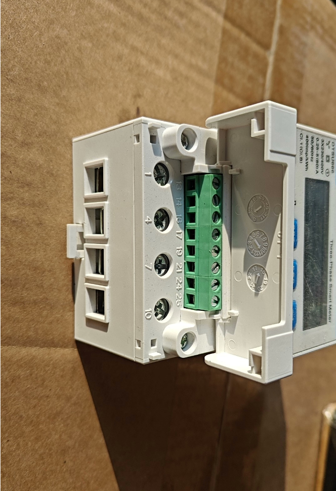 Explicación detallada de la apariencia y el cableado de la interfaz de comunicación RS485 en Chint DTSU666-G
La interfaz de comunicación RS485 del Chint DTSU666-G adopta un diseño de terminal de engarce de tornillo incorporado, ubicado en la zona inferior derecha (cerca del fondo) del contador de electricidad. Es una interfaz de señal diferencial estándar industrial que se utiliza para la adquisición remota de datos y la creación de redes.. A continuación se muestra la guía completa de apariencia y cableado.:
- Apariencia física y ubicación
1.1 Diseño general
Ubicación: Los dos terminales independientes inferiores en el bloque de terminales en el lado derecho del medidor (generalmente marcados como terminales 24 y 25). Algunos modelos pueden estar marcados “A+” y “B-“.
Apariencia: Misma estructura que los terminales de entrada/salida de alimentación., terminales de tornillo (material de latón, antioxidante), adecuado para tamaños de cable de 0,5 a 2,5 mm².
Marcas: Claramente impreso “A+” (RS485+) y “B-” (RS485-) al lado de las terminales. Algunos de los primeros modelos solo muestran números 24 y 25, con la correspondencia: 24 =A+, 25 = B-.
Protección: Misma clase de protección que el cuerpo del medidor principal. (IP20), Adecuado para instalación en gabinetes de distribución de energía para evitar el contacto directo de los dedos con partes vivas..
1.2 Descripción del diagrama físico
[Vista lateral derecha del medidor Chint DTSU666-G]
┌─────────────────────────────┐
│ L1 L2 L3 N (Terminales de potencia) │
│ EN1 EN2 EN3 EN4 (Terminales actuales) │
│P+P- (Terminales de salida de pulsos) │
│A+B- (Terminales de comunicación RS485) │ ← Posición de la interfaz RS485
└─────────────────────────────┘
- Definición de terminales y características eléctricas
2.1 Tabla de definición de terminales estándar
| Número de terminal. | Calificación | Nombre de la señal | Descripción | Requisitos de cableado |
| 24 | A+ | RS485+ | Señal diferencial positiva | Conéctese a RS485+ (A) de host/PLC, usando núcleo de par trenzado blindado |
| 25 | B- | RS485‑ | Señal diferencial negativa | Conéctese a RS485‑ (B) de host/PLC, usando núcleo de par trenzado blindado |
| - | Tierra (optar) | Tierra de señal | Referencia de terreno común (algunos modelos) | Conexión a tierra de un solo punto para evitar interferencias; recomendado |
2.2 Parámetros eléctricos (Igual que el estándar DTSU666)
Protocolo de comunicación: Modbus RTU estándar (para nuevas aplicaciones energéticas), compatible con DL/T645-2007
Velocidad de baudios: 1200 / 2400 / 4800 / 9600 (por defecto) / 19200 bps
Formato de datos: 8 bits de datos + 1 bit de parada, paridad configurable (por defecto: sin paridad)
Distancia de comunicación: máx.. 1200 metros (autobús RS485 estándar); Se recomienda par trenzado blindado
Capacidad de redes: Arriba a 32 dispositivos en un autobús; dirección única (1–247) requerido para cada dispositivo
- Especificaciones y notas de cableado
3.1 Procedimiento de cableado estándar
- Seleccione cable de par trenzado blindado (sección transversal ≥ 0,5 mm²), longitud que no exceda 1200 metros.
- Pele aproximadamente 5 mm de aislamiento para exponer el núcleo de cobre., evitando mechones sueltos.
- Inserte el cable A+ en el terminal 24 y B- cable al terminal 25; apretar los tornillos (esfuerzo de torsión: 2.5 Nuevo Méjico).
- Aplicar conexión a tierra de un solo punto al escudo. (preferiblemente en el extremo del host) para evitar bucles de tierra e interferencias.
- Utilice cableado en cadena para redes de multímetros; La topología en estrella está prohibida.. Se puede agregar una resistencia terminal de 120 Ω en ambos extremos del bus..
3.2 Errores comunes y solución de problemas
A+/B- invertido: Fallo total de comunicación; intercambia los dos cables para restaurar.
Cable no blindado utilizado: Comunicación inestable, susceptible a interferencias electromagnéticas; reemplazar con par trenzado blindado.
Direcciones duplicadas: Algunos medidores no responden; establecer direcciones únicas (1–247) por cada metro.
Autobús demasiado largo: Atenuación de señal más allá 1000 metros; agregue un repetidor RS485 para extender la distancia.
- Diferencias con el estándar DTSU666
La apariencia física de la interfaz RS485 es idéntica entre el Chint DTSU666-G (nueva energía dedicada) y el estándar DTSU666. Las principales diferencias son:
- Protocolo predeterminado: DTSU666-G por defecto es Modbus-RTU (común para fotovoltaica y almacenamiento de energía); La versión estándar por defecto es DL/T645-2007..
- Frecuencia de actualización: Frecuencia de actualización de energía activa ≤ 50 ms en DTSU666-G (para una respuesta rápida del inversor); aprox. 100 ms en la versión estándar.
- Función de medición: DTSU666-G admite medición bidireccional (Potencia activa/reactiva directa/inversa), adecuado para escenarios de autoconsumo fotovoltaico y de alimentación a red.
La interfaz de comunicación RS485 del Chint DTSU666-G consta de terminales de engarce de tornillo incorporados ubicados en la parte inferior derecha del medidor., marcado A+/B- (terminales 24/25). Utiliza un diseño de señal diferencial RS485 estándar y admite cableado de par trenzado blindado.. Distinga estrictamente A+ y B- durante el cableado y garantizar parámetros consistentes con el host para lograr una adquisición de datos de energía remota estable.
¿Le gustaría que le proporcione una lista de configuración de parámetros de comunicación y cableado RS485 lista para copiar según su modelo de host o PLC??

