 contactor,cortacircuitos,inversor solar,medidor electrico,baterias solares

Conclusión: Direct replacement is feasible. The hardware, wiring and core functions are fully compatible. The only difference lies in the software and compliance version indicated by the last digit, which will not affect normal operation. Below is the breakdown of model codes, differences and replacement guidelines.
- Digit-by-Digit Model Code Comparison (Only the last digit differs)
40T-48-4-00-RR-0-0-0-0 (Número de pieza. F000187) vs 40T-48-4-00-RR-0-0-0-1 (Número de pieza. F000188)
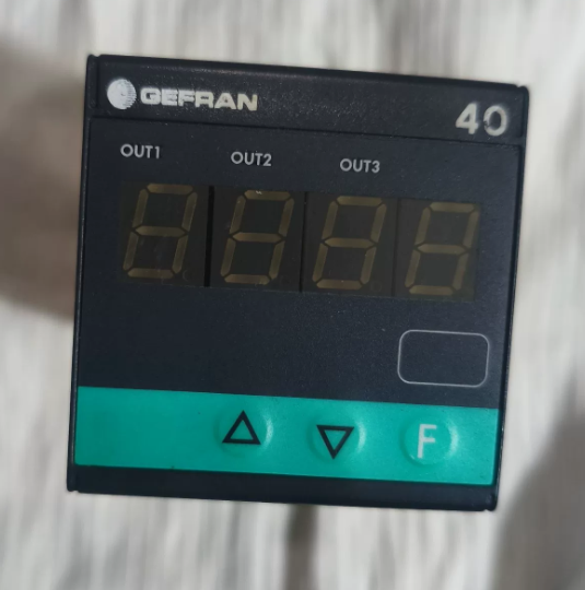
- 40t: Serie (40T48 48×48 mm Indicator / Alarm Unit)
- 48: Panel dimension: 48×48mm (1/16 DE)
- 4: 4-digit LED display
- 00: Fuente de alimentación: 100…240 V AC/DC
- RR: Producción 1 & Producción 2: Dual relays (5A / 250 V y)
- 0: 3rd output / Entrada digital / Transmitter output: Ninguno
- 0: Interfaz de comunicación / 4th output: Ninguno
- 0: Reserved bit
- Last digit: 0 = Legacy software / Versión básica; 1 = Updated software / Compliance certified version (CE, UL, etc.)
- Diferencias clave
Identical hardware: Diseño de terminales, dimensiones de montaje, power supply range, relay contact specifications and input types (Universal input: TC/RTD/Linear signal) are exactly the same. No wiring modification required.
Funciones idénticas: Both support 3 alarm points, on-panel/software programming and parameter password protection. The only distinction is the firmware version and compliance certification. The version ending with 1 is the updated fully compatible firmware.
Números de pieza: Model ending with 0 = F000187; Model ending with 1 = F000188.
- Recomendaciones de reemplazo & Notas
- ✅ Direct replacement: Fully compatible in terms of installation, wiring and terminal definition. No rewiring needed.
- ⚠️ Mandatory operation: Reconfigure parameters (input type, rango de medición, umbral de alarma, differential gap, etc.) after replacement. The new firmware is fully compatible with legacy parameter logic.
- Special scenario: If the original equipment requires traceability of special compliance certifications (p.ej. matching UL/CE documents), verify whether strict model consistency is required on site. For general functional use, no issues will occur.
Quick Reference for Replacement: GEFRAN 40T-48-4-00-RR-0-0-0-0 / 40T-48-4-00-RR-0-0-1
- Full Model Code Explanation (Only the last digit differs)
| Segmento de código | Contenido | Descripción | Consistency Between Two Models |
| 1 | 40t | Serie de productos: 40T Digital Alarm Controller | Totalmente idéntico |
| 2 | 48 | Panel Size: 48×48mm (1/16 Tu estándar) | Totalmente idéntico |
| 3 | 4 | Mostrar: 4-digit LED Digital Tube | Totalmente idéntico |
| 4 | 0 | Fuente de alimentación: Wide voltage 100~240 V AC/DC | Totalmente idéntico |
| 5 | RR | Configuración de salida: Two independent relay alarm outputs | Totalmente idéntico |
| 6 | 0 | 3rd output / Entrada digital / Transmitter output: Ninguno | Totalmente idéntico |
| 7 | 0 | Communication port / 4th output: Ninguno | Totalmente idéntico |
| 8 | 0 | Hardware reserved bit: Disabled reserved functions | Totalmente idéntico |
| 9 | 0 / 1 | Firmware & Compliance Version: | Only difference |
| 0 = Basic firmware | |||
| 1 = Updated firmware (CE/UL certified) |
> Conclusión central: 100% compatibility in hardware structure, especificaciones electricas, terminals and functional pins. Direct replacement is supported.
- Especificaciones técnicas generales (Identical for both models)
| Artículo | Especificación |
| Dimensión de montaje | 48×48 mm panel, standard DIN cutout |
| Operating Power | 100 ~ 240 VCA/CC, Power consumption < 3 Virginia |
| Measuring Input | tipo universal: Thermocouple (K/J/S/T), Pt100 RTD, linear voltage/current analog signal |
| Display Accuracy | ±0,2 % escala completa, Sampling rate: 10 veces por segundo |
| Salida de relé (RR) | 2-channel passive normally open contacts, Calificación de contacto: 5A / 250 V y |
| Temperatura de funcionamiento | 0 ~ +50 ℃ |
| Protección de ingreso | Panel frontal: IP65; Terminal side: IP20 |
| Rigidez dieléctrica | Withstand voltage 2000 V AC between input, output and power supply |
- Terminal Pin Definition (Universal for on-site wiring, no rewiring)
Standard terminal block on the rear of the device, total 8 terminales. Terminal layout and functions are fully identical for both models.
| Número de terminal. | Función | Instrucciones de cableado | Observaciones |
| 1 | Power L / + | AC Live / DC Positive | Entrada de energía |
| 2 | Power N / – | AC Neutral / DC Negative | Entrada de energía |
| 3 | Measuring Input + | Sensor signal positive | Connect to thermocouple/RTD/analog output |
| 4 | Measuring Input – | Sensor signal negative | Common end of signal loop |
| 5 | Alarm Relay 1 NO contact | 1st alarm output | Corresponds to the 1st alarm logic |
| 6 | Alarm Relay 1 Común | Common terminal of Relay 1 | Passive contact, non-polar |
| 7 | Alarm Relay 2 NO contact | 2nd alarm output | Corresponds to the 2nd alarm logic |
| 8 | Alarm Relay 2 Común | Common terminal of Relay 2 | Passive contact, non-polar |
Suplemento: This model has no transmitter output or communication port, and all terminals are fully utilized. Wire strictly in accordance with the above table.
- Panel Keys & Step-by-Step Parameter Configuration (Mandatory after replacement)
Descripción clave
`SET`: Enter menu / Confirm parameter / Switch menu level
`▲/▼`: Adjust value / Switch options
`◀`: Shift digit / Return to previous menu
Complete Configuration Steps (General for field application)
Paso 1: Enter Programming Mode
Press and hold `SET` for 3 seconds to enter parameter setting interface. For some units, enter the factory default password 0000 and press `SET` to confirm.
Paso 2: Set Input Signal Type (Core setting)
- Locate parameter `In.Ty` (Tipo de entrada)
- Use `▲/▼` to select the sensor type:
`K`: K-type Thermocouple
`Pt`: Pt100 RTD
`0-10`: 0-10V Analog Signal
`4-20`: 4-20mA Analog Signal
- Press `SET` to save and proceed to the next item.
Paso 3: Set Measuring Range
- `Lo`: Set Lower range limit
- `Hi`: Set Upper range limit
- Adjust according to actual process range, then press `SET` to confirm.
Paso 4: Configure Dual Alarm Relays (Corresponding to RR outputs)
- `AL1`: 1st alarm value (for Relay on Terminal 5/6)
- `dF1`: Differential gap of 1st alarm (to prevent frequent relay switching, recommended value: 0.5~2.0)
- `AL2`: 2nd alarm value (for Relay on Terminal 7/8)
- `dF2`: Differential gap of 2nd alarm
- Select alarm mode: High limit alarm / Low limit alarm as required.
Paso 5: Guardar parámetros & Salida
After all settings are completed, press `◀` repeatedly to return to the main interface. Parameters will be saved automatically.
To lock parameters against accidental modification: Locate `P.cod` and set a custom password.
- On-site Check List after Replacement (Check item by item to avoid faults)
Inspección previa al encendido
- Mechanical mounting: Secure the instrument on the panel without looseness; cutout size complies with 48×48 mm.
- Verificación de cableado: Verify power, sensor and relay circuits per terminal table; ensure no loose connection, wrong wiring or short circuit.
- Power confirmation: On-site power supply is 100~240 V AC/DC within rated range.
Post-power-on Inspection
- Power-on test: 4-digit LED lights up normally, no black screen or flickering.
- Signal verification: Compare real-time reading with actual sensor value; ensure deviation is within allowable range.
- Alarm test: Simulate over-limit conditions manually; confirm two relays actuate/de-energize normally and external loads work properly.
- Parameter recheck: Keep range, alarm values and differential gap consistent with original settings.
Compliance Check (Execute as required)
General industrial sites / No certification traceability required: No extra operation needed.
Export equipment / Strict model & certificate consistency required: The new model ending with 1 is the certified version with complete CE/UL documents for filing.
- Fallos comunes & Troubleshooting after Replacement
| Fenómeno de falla | Posibles causas | Soluciones |
| No display after power-on | 1. Reversed/loose power wiring | Reapretar terminales, measure input voltage and restore rated power supply |
| 2. Supply voltage out of range | ||
| Fluctuating / Inaccurate readings | 1. Poor sensor connection | Reconnect sensor cables and verify In.Ty parameter |
| 2. Wrong input type selected | ||
| Normal reading but relay no action | 1. Incorrect alarm value | Recheck AL1/AL2 thresholds and switch alarm mode |
| 2. Wrong alarm mode selected | ||
| Relay switches frequently | Excessively small differential gap | Increase dF1/dF2 value |
| Parameters reset automatically | Failed to exit menu completely / Stuck panel keys | Fully exit setting interface and clean foreign matters on keys |
- Notas complementarias
- Firmware compatibility: The updated firmware (ending with 1) is fully backward compatible with legacy parameter logic, with no function reduction or protocol mismatch.
- Spare parts procurement: Both models are interchangeable for reordering. The updated version ending with 1 is recommended for wider certification coverage.
- Long-term operation: The two models have identical service life and load capacity, and require no differentiated maintenance standards.

