 contactor,cortacircuitos,sensor,Codificador,SOCIEDAD ANÓNIMA,Convertidor

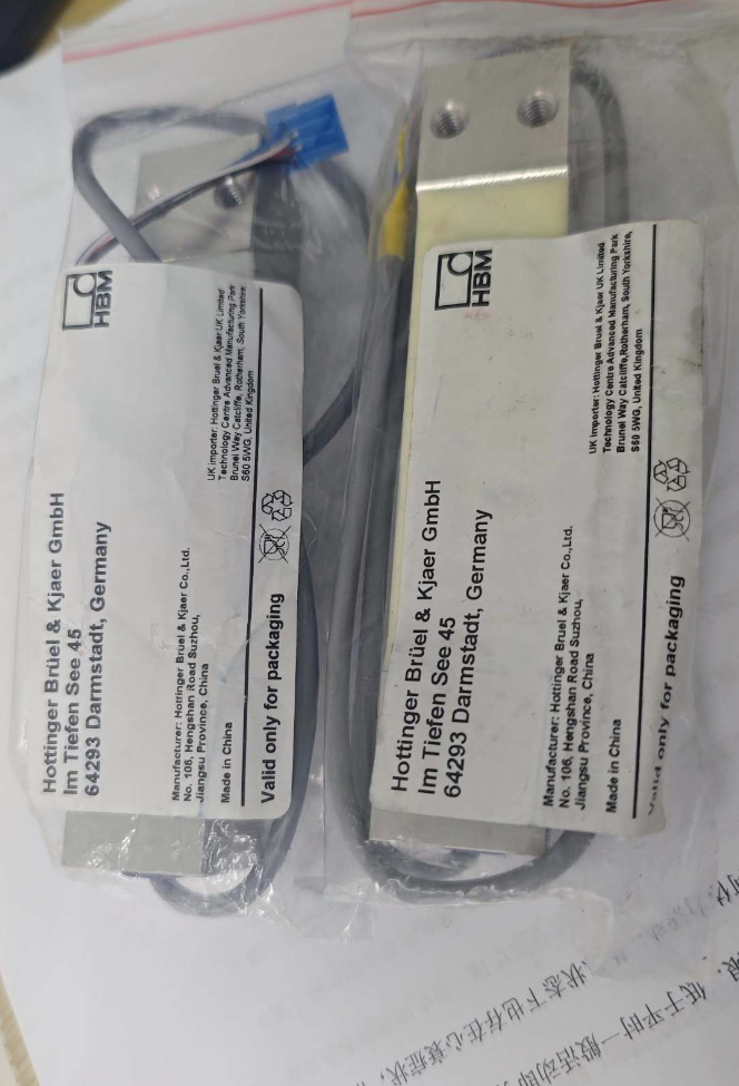

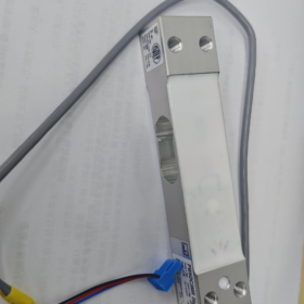
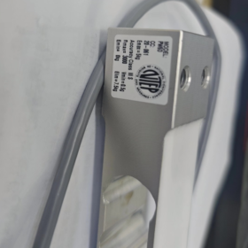
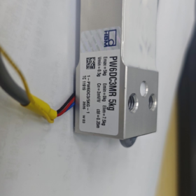
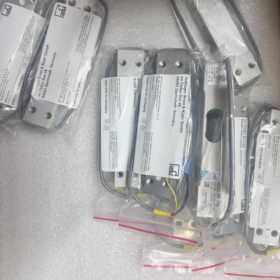
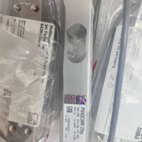
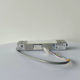
PW6DC3MR/XXkg
PW6D: Serie de productos, single-point type optimized for high-speed dynamic weighing
C3: Accuracy class of 3,000 verification divisions in accordance with OIML R60
MR = Multi-Range: Compared with standard C3 version, it supports a smaller minimum verification interval, suitable for multi-range weighing instruments
XXkg: Capacidad nominal (3/5/10/15/20/30/40kilos)
Complete ordering model example: 1-PW6DC3MR/10KG-1
- Especificaciones principales
- Capacity Options
3kilos, 5kilos, 10kilos, 15kilos, 20kilos, 30kilos, 40kilos
- Parámetros eléctricos
Salida nominal: 2.0 mV/V
Bridge Input Resistance: ~350 Ω
Voltaje de excitación recomendado: 5~12 V DC (máx.. 15 En DC)
Construcción: 6-diseño de alambre (cable can be trimmed) to eliminate measurement error caused by cable voltage drop; compatible with 4-wire instruments
Resistencia de aislamiento: >2000 MΩ
- Exactitud & Certificaciones
OIML R60 C3MR, nLC=3000 divisiones
Compensación de carga descentrada que cumple con OIML R76; dimensión máxima de la plataforma para una sola celda de carga: 300×300mm
No linealidad / Histéresis / Repetibilidad: ≤±0,017 %FS
- Mecánico & Especificaciones ambientales
Material: aleación de aluminio
Clase de protección: IP67
Deflexión nominal: 0.18~0,29mm (Alta rigidez, respuesta dinámica rápida)
Rango de temperatura compensado: -10 ℃ ~ +40 ℃
Rango de temperatura de funcionamiento: -10 ℃ ~ +50 ℃
Sobrecarga segura: 150%FS; Sobrecarga definitiva: 300%FS
Perno de montaje: M6; Par de apriete recomendado: 10 Nuevo Méjico
- Ventajas clave
✅ Optimizado para pesaje dinámico: Alta frecuencia natural, ideal para control de peso de alta velocidad y llenado volumétrico
✅ Compensación de carga descentrada incorporada para minimizar el error de excentricidad de la plataforma
✅ Sellado IP67, Aplicable en ambientes de producción húmedos y polvorientos.
✅ El cable blindado de 6 hilos garantiza una señal estable para cableado de larga distancia
✅ La variante MR de rango múltiple admite intervalos de verificación más pequeños, compatible con equipos de pesaje comerciales legalmente verificados
- Aplicaciones típicas
Controladoras de peso en línea, máquinas clasificadoras de peso
Envasado automático a pequeña escala., polvo & equipo de llenado de partículas
Básculas de plataforma industriales, pesadoras combinadas de cabezales múltiples
Monitoreo dinámico de peso en líneas de producción automatizadas
- Definición de cableado (Cable blindado estándar de 6 hilos)
| Señal | Color típico del cable |
| +Excitación positiva positiva | Azul |
| -Excitación negativa negativa | Negro |
| +Sentido Sentido Positivo | Verde |
| -Sentido Sentido Negativo | Gris |
| +Señal positiva | Blanco |
| -Señal negativa | Rojo |
| Blindaje | Verde/Amarillo |
Para instrumentos de 4 hilos: Cortocircuito +Sense a +Exc, y -Sense a -Exc
- Misma serie & Referencias alternativas
- PW6DC3: Precisión estándar C3 (no RM), menor costo, no puede admitir pequeños intervalos de verificación de múltiples rangos
- PW2DC3MR: Célula de carga de un solo punto de tamaño más pequeño de HBM, con un tamaño de plataforma máximo permitido más pequeño
- Alternativas domésticas: Células de carga C3 de un solo punto de Zemic, A&D, Instrumentos de medición electrónicos Zhonghang. Verificar la disposición de los orificios de montaje, Clasificación mV/V y tamaño máximo de plataforma antes del reemplazo.
- Precauciones de instalación
- Las superficies de montaje deben ser planas y rígidas.. No suelde ni golpee el cuerpo de la celda de carga..
- Apriete los pernos M6 estrictamente al 10 N·m para evitar roturas de roscas en carcasas de aluminio.
- La carga se aplicará verticalmente hacia abajo.; Evite la fuerza lateral y el impacto de torsión..
- Evite la flexión mecánica y la tensión en la salida del cable.; Se recomienda conexión a tierra de un solo extremo para blindaje..
Guía completa de selección de celdas de carga (Ilustrado con celda de carga de punto único HBM PW6DC3MR)
Paso 1: Confirmar tipo de estructura mecánica (Prioridad más alta)
Haga coincidir la estructura de la celda de carga según la condición de carga:
| Escenario de aplicación | Tipo recomendado | Aplicabilidad para PW6DC3MR |
| Célula de carga única que soporta una plataforma, controladora de peso, pequeña escala de embalaje | Celda de carga de un solo punto ✅ | PW6DC3MR es del tipo de punto único. Compensación de excentricidad incorporada; una plataforma requiere solo una celda de carga |
| Tolvas de material, contenedores, básculas de plataforma multicelular | Haz de corte / Viga voladiza | ❌ No aplicable a PW6D |
| Pesaje de tensión, balanzas colgantes | Celda de carga de viga S | ❌ No aplicable a PW6D |
| Básculas para camiones pesados, pesaje de tanques | Columna / Célula de carga de radios | ❌ No aplicable a PW6D |
Restricción estricta de PW6DC3MR: Dimensión máxima de la plataforma: 300×300mm. La plataforma que excede este tamaño causará un error de excentricidad excesivo.
Paso 2: Cálculo de capacidad (Error más común en la selección)
Fórmula de cálculo
Capacidad nominal de la celda de carga ≥ (Peso muerto de la plataforma + Peso máximo del producto) × Factor de seguridad
Pesaje estático estable: Factor de seguridad 1,2~1,3
Control de peso dinámico, impacto de caída de material, línea de producción vibratoria: 1.5~2.0 (1.5 recomendado)
Ejemplo práctico (PW6DC3MR)
Peso muerto de la plataforma = 1,5 kg, peso máximo del producto = 10 kg, control de peso dinámico en línea:
Carga total = 1.5 + 10 = 11,5 kilos; 11.5 × 1.5 = 17,25 kilos
Selección de prioridad: PW6DC3MR/20KG. Evite 15 kg (margen insuficiente) y capacidad excesiva de 30kg (mala resolución para cargas ligeras).
⚠️ Dos reglas críticas:
- No opere continuamente cerca de su capacidad total;
- No sobredimensionar excesivamente la capacidad, lo que degrada la resolución para mediciones de bajo peso.
Paso 3: Selección de clase de precisión (C3 / C3MR / Comparación C6)
Tomemos como ejemplo la serie HBM PW6D:
- C3: Estándar 3000 divisiones, para pesaje industrial general, incapaz de lograr intervalos de verificación ultrapequeños
- C3MR (Tu modelo): Variante de rango múltiple, Certificado OIML R60, admite intervalos de verificación mínimos más pequeños (mín.)
✅ Adecuado para equipos que requieren certificación de metrología legal, control de peso de alta velocidad, llenado volumétrico y alta resolución de pantalla (medición de nivel de gramo)
- C6: 6000 divisiones, mayor precisión, mayor costo, Requisitos más estrictos para la rigidez del montaje y el entorno operativo.
Regla de selección rápida para C3 vs C3MR
El equipo requiere certificación metrológica comercial., control de peso de alta precisión, intervalo de pequeña escala (nivel de gramo) → PW6DC3MR
Sólo seguimiento de procesos internos., no se requiere certificación de pesaje, requisitos de precisión flexibles → PW6DC3 (versión estándar)
Indicadores clave de precisión para revisar: No linealidad, histéresis, repetibilidad, arrastrarse, error de deriva de temperatura.
Paso 4: Entorno operativo, Material & Clase de protección
- Material
PW6DC3MR: aleación de aluminio; Adecuado para alimentos secos estándar y talleres automatizados..
Para lavado, húmedo o corrosivo / ambientes con niebla salina: Prefiere celdas de carga de un solo punto de acero inoxidable.
- Clase de protección
PW6D: IP67, a prueba de polvo y salpicaduras; NO para inmersión permanente.
Para equipos completamente lavados o instalación bajo el agua.: Se requieren celdas de carga herméticamente selladas IP68.
- Rango de temperatura
rango compensado: -10~+40℃; El funcionamiento prolongado fuera de este rango provoca una grave deriva del cero.. Se necesitan modelos personalizados de amplia temperatura para condiciones de temperatura extremas.
- Protección contra explosiones: Para áreas explosivas peligrosas, Utilice células de carga certificadas intrínsecamente seguras.. El PW6DC3MR estándar no es a prueba de explosiones.
Paso 5: Coincidencia de parámetros eléctricos con el instrumento
- Sensibilidad: PW6DC3MR = 2.0 mV/V, La especificación más común para pesaje industrial.; confirmar la compatibilidad del instrumento.
- Tipo de cableado: PW6D adopta 6 cables (con líneas de retroalimentación sensorial)
Instrumento compatible con 6 hilos.: Cableado completo para eliminar la caída de voltaje del cable
Instrumento que solo admite 4 cables.: Cortocircuito +Sense a +Exc, -Sense to -Exc
- Excitation Voltage: Recommended 5~12 V DC, máximo 15 En DC
- Bridge Resistance: ~350 Ω input resistance, compatible with standard weighing transmitters
Paso 6: Mechanical Dimension Verification (Fácilmente pasado por alto)
- Overall length, altura, mounting hole pitch, thread specification (PW6D uses M6 mounting bolts)
- Check mechanical installation space
- Ensure vertical load transmission; structure design shall eliminate lateral force and torque
PW6D mounting torque standard: M6 bolt tightening torque 10 Nuevo Méjico. Aluminum housing risks thread damage under excessive torque.
Paso 7: Distinguish Dynamic / Static Application Scenarios
Static Weighing (Warehouse Platform Scale): Standard C3 is sufficient; prioritize long-term zero stability
Dynamic Weighing (Inline Checkweigher, Online Sorting): PW6DC3MR preferred; optimized high natural frequency, fast response and vibration resistance
Common Selection Mistakes Checklist
❌ Considere únicamente el peso máximo del producto sin incluir el peso muerto de la plataforma
❌ Utilice la celda de carga de un solo punto PW6D para plataformas de más de 300×300 mm, resultando en un error de excentricidad excesivo
❌ Adopte un factor de seguridad de sólo 1.2 bajo impacto dinámico, provocando fatiga del elemento elástico y daño permanente
❌ Compre C3 estándar en lugar de C3MR cuando se requiera certificación de pesaje, No cumplir con el requisito mínimo de intervalo de escala.
❌ Seleccione una celda de carga de aluminio IP67 para ambientes húmedos de lavado, lo que lleva a la entrada de agua a largo plazo y fallas prematuras
❌ La capacidad excesiva provoca lecturas inestables y mala resolución en productos livianos
Plantilla de selección rápida (Listo para uso directo)
- Estructura: Punto único ✅ (Plataforma ≤300×300 mm)
- Carga total: Plataforma ____kg + Producto máximo ____kg = ____kg × Factor de seguridad ____ = ____kg → Modelo seleccionado PW6DC3MR/____kg
- Exactitud: Se requiere certificación metrológica? Sí → C3MR; No → C3
- Ambiente: taller seco, IP67 aceptable; Lavado / ambiente corrosivo → cambiar a celda de carga de acero inoxidable
- Eléctrico: Soportes para instrumentos 2.0 mV/V; confirmar cableado de 6 o 4 hilos
- Instalación: Verificar dimensión, Espacio de montaje M6, estructura de transmisión de fuerza vertical
Cómo determinar la posición de montaje de las celdas de carga
Explicación basada en la celda de carga de un solo punto HBM PW6DC3MR (plataforma unicelular); También se incluyen reglas generales para plataformas de pesaje de múltiples celdas..
- Distinguir dos tipos estructurales: Punto único versus celda múltiple
(1) Celda de carga de un solo punto (PW6DC3MR, celda única que soporta una plataforma)
Las celdas de carga de un solo punto cuentan con compensación de carga descentrada incorporada.
Posición de montaje estándar: Centro geométrico del fondo de la plataforma.
✅ Disposición óptima:
Alinee el centro del orificio de carga de la celda de carga con el centro de largo y ancho de la plataforma..
Dimensión máxima permitida de la plataforma: 300 × 300 milímetros (Límite de especificación PW6D)
⚠️ Restricciones críticas:
Si la celda de carga se desvía del centro:
El error de excentricidad aumenta
Lecturas inconsistentes cuando el peso se coloca en las cuatro esquinas
Incluso una instalación centrada no puede compensar el error si la plataforma excede el límite máximo de dimensiones del fabricante.
método práctico: Dibuja dos diagonales de la plataforma rectangular.; la intersección es la posición de montaje central.
(2) Estructura multicelular (3/4 Células de carga en voladizo/viga de corte, Básculas de plataforma, Tolvas de almacenamiento)
La posición de montaje sigue el principio de distribución uniforme de la carga según el centro de gravedad.
- Plataforma rectangular con cuatro células de carga.: Dispuestos simétricamente cerca de las cuatro esquinas.
- Contenedor de almacenamiento circular con tres células de carga.: Distribuido uniformemente en un diseño de triángulo equilátero.
- Objetivo: La carga transportada por cada celda de carga debe ser lo más uniforme posible en condiciones de carga completa y vacía.
- Cinco principios universales para todos los sistemas de pesaje
Principio 1: El centro de gravedad combinado debe estar dentro de la envolvente de soporte de las células de carga.
- condición descargada: El centro de gravedad del peso propio de la plataforma se encuentra dentro del área de soporte.
- Condición completamente cargada: Cuando el material se coloca en máxima excentricidad., El centro de gravedad combinado general permanece dentro de la envolvente de soporte.
Si el centro de gravedad se mueve fuera de la región de apoyo: Riesgo de vuelco de la plataforma, y la celda de carga soporta una enorme fuerza lateral y torque, provocando daños permanentes.
Principio 2: Elimine la fuerza lateral y el torque en las celdas de carga
Las celdas de carga solo soportarán fuerza de compresión vertical.
❌ Condiciones prohibidas:
Fuerza del componente lateral generada por la posición de montaje sesgada
Torque inducido por rigidez insuficiente del marco de soporte
✅ Solución:
Diseñar topes mecánicos para restricción horizontal.. Mantenga un pequeño espacio vertical; los topes no deben soportar carga vertical.
Principio 3: Garantizar la transmisión de fuerza vertical
La superficie de carga de la célula de carga debe estar paralela a la superficie inferior de la plataforma de pesaje..
La base de montaje debe ser plana y rígida.; Evite la suspensión de placas delgadas y el contacto concentrado local..
La carcasa de aluminio PW6DC3MR prohíbe la carga por contacto puntual.
Principio 4: Evite fuentes de vibración fuertes y tensión de expansión térmica
Selección de la posición de montaje:
Manténgase alejado de fuentes de vibraciones fuertes, como motores y rodillos transportadores.
La expansión/contracción térmica de marcos largos puede tirar de la celda de carga.; Se requiere una estructura de soporte deslizante cuando sea necesario.
Principio 5: Evite la tensión de tracción en la salida del cable
La salida del cable del PW6DC3MR está al final del sensor..
Requisito de disposición: Reservar bucles de cable flojos; Evite la tensión y la flexión repetida en la raíz del cable para evitar la rotura interna del cable..
- Posicionamiento paso a paso para plataforma de un solo punto (PW6DC3MR)
- Medir la dimensión externa de la plataforma: Largo L × Ancho W
- Calcular las coordenadas del centro.: L/2, con 2
- Alinee el centro del orificio de carga de la celda de carga con el punto central calculado
- Verificación de dimensiones de la plataforma:
≤300×300 milímetro: Instalación centrada normal
>300×300mm: PW6D no se puede utilizar. Cambie a una celda de carga de un solo punto más grande o a una solución de celdas múltiples
- Verificación de la prueba de peso:
Coloque los pesos de calibración secuencialmente en las cuatro esquinas de la plataforma y observe la desviación de la lectura..
Un error excesivo en las cuatro esquinas indica una posición desviada de la celda de carga o una plataforma demasiado grande.
- Operación de posicionamiento en las cuatro esquinas para una plataforma multicelda (4 Ejemplo de celda de carga)
- Diseño simétrico; cuatro puntos de apoyo forman un rectángulo
- Deje un margen adecuado entre los puntos de apoyo y el borde de la plataforma.; Evite colocar demasiado cerca de los bordes.
- Nivelación aproximada bajo carga vacía con precarga
- Realice una calibración de error de cuatro esquinas después de cargar pesos en cada esquina
- Instalar topes mecánicos para evitar que la plataforma se deslice bajo impacto.
- Errores comunes de posición de montaje
- Célula de carga de un solo punto instalada lejos del centro de la plataforma → lecturas inconsistentes en las cuatro esquinas
- Plataforma sobredimensionada que todavía usa celda de carga de un solo punto PW6D → error de excentricidad excesivo
- Rigidez insuficiente del marco de soporte.; La deformación del marco bajo carga induce torsión en la celda de carga.
- Topes mecánicos bloqueados; La expansión térmica crea una fuerza adicional que conduce a una deriva cero continua.
- Células de carga dispuestas demasiado cerca de los bordes; El centro de gravedad se mueve fuera de la envoltura de soporte cuando el material se coloca excéntricamente.
- La tensión de la correa crea una fuerza de tracción horizontal transferida a la celda de carga en las controladoras de peso en línea (Se requiere un marco independiente para aislar la tensión de la correa)
- Consejos adicionales para su equipo (Controladora de peso con PW6DC3MR)
Para controladoras de peso en línea: El bastidor de la cinta transportadora no deberá estar fijado rígidamente a la plataforma de pesaje..
El motor del transportador y la tensión de la correa producen una fuerza de tracción horizontal continua..
Solución recomendada: Only the weighing platform carries products; the conveyor frame stands independently on the ground to isolate horizontal force.





NH42-63-318x560.png "Interruptores de transferencia automática tipo PC CHINT (ATS)NH42-63/4SZ")



