 contactor,cortacircuitos,sensor,Codificador,SOCIEDAD ANÓNIMA,Convertidor

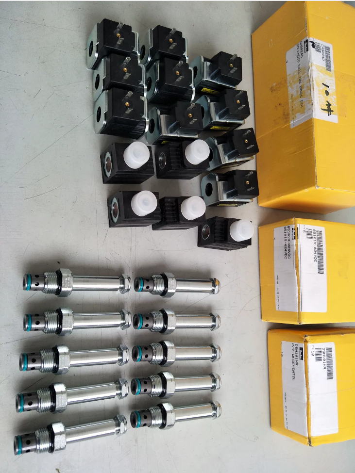

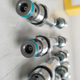
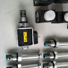
DSH101NR
DSH101: Serie – Solenoide tipo disco de 2 vías válvula de cartucho, cavidad estándar C10-2
N = Normalmente Abierto: Abierto cuando está desenergizado, cerrado cuando está energizado
R = flujo libre inverso
Función: Flujo permitido 2→1 cuando está abierto; cerrado al momento de la energización; flujo inverso libre 1→2 (función de verificación integral)
- Especificaciones técnicas principales
| Artículo | Parámetro |
| Tipo de válvula | 2-válvula de cartucho de solenoide de asiento de 2 vías de posición |
| Cavidad de montaje | Cavidad estándar C10-2 |
| Presión máxima de funcionamiento | 350 bar (5000 psi) |
| Flujo nominal | 60 l/min (15 GPM) |
| Fuga cerrada | Aprox.. 0.33 cc/min (5 gotas/min, 32aceite hidráulico cst) |
| Tiempo de respuesta | Cierre (energizado): ≈70 ms; Apertura (desenergizado): ≈35 ms |
| Material del cuerpo de la válvula | Todo acero, componentes móviles endurecidos |
| Medios compatibles | aceite mineral, fluido hidráulico sintético; Rango de viscosidad: 6~420 cSt |
| Requisito de filtración | ISO 4406 18/16/13 o superior |
| Sello estándar | Anillo en D de PU; NBR opcional, FKM |
| Temperatura de funcionamiento | Sello de PU: -37℃~+93℃ |
| Torsión de instalación | Cartucho: 69~75 N·m; Tuerca de bloqueo del solenoide: 7~10 N·m |
| Peso | Aprox.. 0.2 kilos |
- Lógica operativa
- Solenoide desenergizado (estado normal): Válvula abierta → Puerto 2 ↔ Puerto 1 conectado
- Solenoide energizado: El solenoide acciona el obturador para cerrar → Flujo 2 → 1 bloqueado; El flujo libre 1→2 permanece disponible
Aplicaciones típicas: Alivio de presión del cilindro de simple efecto, retención de carga, corte de bajada, circuitos de descarga de acumuladores
- Opciones de sufijo comunes (Ejemplos de modelos completos)
DSH101NR24: 24bobina VCC (más común)
DSH101NR12: 12bobina VCC
DSH101NRMS: Con botón de anulación manual
DSH101NRTN: Conector alemán DT04
DSH101NREVS: Conector de la serie Deutsch EV
- Comparación rápida de series (Guía de selección)
DSH101C / CR: Normalmente cerrado (CAROLINA DEL NORTE)
DSH101N / NR: Normalmente abierto (NO)
Sufijo sin R: Flujo inverso restringido; Sufijo R = Flujo inverso libre (NR/CR)
- Referencia equivalente nacional
Válvula de asiento solenoide de 2 vías de cavidad C10-2 intercambiable con NO + flujo inverso libre:
HidraForce SV10-21, Vickers, ADEREZO, Válvulas de cartucho equivalentes a Jialang.
A pedido, puedo proporcionar:
- Dibujo de dimensiones de texto para la cavidad del colector C10-2
- Dibujo de circuito típico (control de descenso del cilindro de simple efecto)
- Extractos de la hoja de datos del fabricante original
Escenarios de aplicación de parker DSH101NR
Resumen de funciones clave para referencia de selección
DSH101NR: Normalmente abierto + Flujo libre inverso
Desenergizado: Pasaje 2→1 abierto; energizado: 2→1 bloqueado; flujo libre permanente 1→2 (característica de válvula de retención incorporada)
La construcción de asiento proporciona bajas fugas cerradas.; Cavidad de montaje C10-2, máximo 350 bar, flujo nominal 60 l/min.
- Hidráulica Móvil (Campo de aplicación principal)
1.1 Elevación de cilindros de simple efecto & Circuito de descenso de carga (Uso típico)
Cilindros estabilizadores & Cilindros telescópicos de simple efecto en plataformas aéreas de trabajo.
camión volquete, cilindros de elevación de equipos sanitarios
Sujeción de materiales & Cilindros hidráulicos de compresión de simple efecto para maquinaria de construcción.
Lógica de operación del circuito:
Estado desenergizado: Lado de la tapa del cilindro conectado al tanque, El cilindro desciende bajo el peso de la carga.
Estado energizado: Ruta del tanque bloqueada, Cilindro bloqueado para retención de carga.
Durante el levantamiento, el aceite a presión fluye libremente 1→2 (El flujo inverso libre del sufijo R suministra flujo de elevación, no se requiere válvula de retención separada)
✅ Ventaja: Una sola válvula realiza el control de encendido/apagado de descenso + función de control de elevación, simplifica el diseño del circuito múltiple.
1.2 Descarga de seguridad del acumulador / Circuito de alivio de presión
Sistemas de retención de presión del acumulador.:
Apagado de la máquina / condición de emergencia: Solenoide desenergizado, presión del acumulador aliviada mediante 2→1
funcionamiento normal: Solenoide energizado, Circuito del acumulador sellado para mantener la presión.
Carga del sistema: El fluido fluye libremente 1→2 hacia el acumulador
Ampliamente utilizado: Pinzas hidráulicas móviles, Circuitos del acumulador del martillo hidráulico..
1.3 Control de drenaje de frenos para motores hidráulicos unidireccionales
Controla la línea de contrapresión del motor para motores hidráulicos rotativos unidireccionales:
Energizado para bloquear la contrapresión para frenar.; desenergizado para abrir el circuito y permitir la rotación del motor.; el aceite de suministro pasa libremente a través de 1→2.
- Unidades de energía hidráulica industriales
2.1 Abrazaderas hidráulicas & Equipo de prensa: cilindros de sujeción de simple efecto
Extensión de abrazadera: El aceite a presión fluye libremente 1→2
Retracción de la abrazadera: Primavera / El peso de la carga retrae el cilindro cuando la válvula se desactiva para abrir la línea del tanque.
En espera durante la producción: Solenoide energizado para bloquear la línea de retorno y mantener la fuerza de sujeción; La baja fuga del obturador minimiza la caída de presión..
2.2 Alivio de la cámara de presión & Válvula de descarga de seguridad
Hidráulica del molde, bancos de pruebas hidraulicos:
Energizado para sellar la cámara de alta presión durante la operación.; desenergizado para despresurizar automáticamente la cámara después de completar el proceso o activar el gatillo de seguridad.
2.3 Selector de circuito & Circuito de descarga de derivación de la bomba
Descarga de bypass de bomba: Normalmente abierto (desenergizado) para descarga directa de la bomba; energizado para cortar el camino de descarga y aumentar la presión del sistema..
- Condiciones de trabajo inadecuadas (Errores de selección)
- Bloqueo bidireccional para cilindros de doble efecto ❌
Sólo bloquea el flujo 2→1; path 1→2 is permanently open, cannot seal both directions. For bi-directional pressure holding, select DSH101CR or bi-directional poppet valves.
- Application requiring load holding after power loss, relief on energization ❌
DSH101NR: De-energized open, energized closed. If load must remain locked when power fails, select DSH101CR (Normalmente cerrado, flujo inverso libre).
- Continuous steady flow exceeding 60 l/min: Upgrade to DSH161 series.
- Function Comparison for Fast Selection
DSH101NR: Normalmente abierto, free reverse flow → De-energized relief, energized load holding (first choice for single-acting cylinder lowering)
DSH101CR: Normalmente cerrado, free reverse flow → De-energized load holding, energized relief (safety critical power-off holding applications)
Installation Guidelines for Parker DSH101NR (C10-2 Cavity)
- Inspección previa a la instalación (Crítico)
1.1 Verify Model & Función de válvula
DSH101NR: Normalmente abierto + Flujo libre inverso
Definición de puerto: 2→1 controlled flow path; flujo libre permanente 1→2
⚠️ Reversed port connection will completely invalidate circuit function!
La marca del puerto del colector debe coincidir con la dirección del flujo de la válvula..
1.2 Inspección de la cavidad del colector
Cavidad estándar: SAE C10-2. El mecanizado no estándar provocará fugas en el sello y atascamiento de la válvula..
Limpiar a fondo la cavidad: Quitar virutas de metal, rebabas y restos de sellado. Enjuague con aceite a alta presión; no inserte hilo de algodón en la cavidad (riesgo de contaminación de la fibra y agarrotamiento de la válvula).
Inspeccione la cara de sellado en busca de rayones.; El daño a la superficie causará fugas externas del anillo en D exterior..
1.3 Verificación del sello
Anillo en D de poliuretano PU estándar (no se requiere anillo de respaldo)
aceite mineral, temperatura normal: PU (-37~93℃)
Temperatura alta / fluido sintético: Reemplazar con sello de fluorocarbono NBR o FKM
Nunca reutilice los sellos retirados. Lubrique ligeramente con aceite hidráulico limpio antes de la instalación.. No use grasa (riesgo de carbonización y atasco de válvulas).
- Torque de instalación del cartucho (Estándar OEM)
Torsión roscada del cartucho en el colector: 69~75 N·m
✅ La llave dinamométrica es obligatoria!
Par insuficiente: Sellado incompleto del anillo en D exterior → fuga externa
Torque excesivo: pelado de hilos, deformación de la cavidad múltiple, daño de la válvula interna, funcionamiento lento y aumento de fugas.
Procedimiento de instalación:
- Asegúrese de que el sello esté completamente asentado en la ranura del cartucho sin torsión ni extrusión.
- Enrosque el cartucho manualmente hasta que el sello entre en contacto con la cara del colector
- Apriete al par especificado con una llave dinamométrica
- NO gire el cartucho agarrando la carcasa del solenoide.; Sujete sólo la sección roscada hexagonal.!
- Requisitos de montaje de la bobina de solenoide
- Par de apriete de la tuerca de bloqueo del solenoide: 7~10 N·m
Apretar demasiado corre el riesgo de agrietar la carcasa del solenoide.
- Secuencia de montaje:
Colocación de la arandela en la parte superior del cartucho → Deslice la bobina sobre el pasador del actuador → Asegure con la tuerca de bloqueo.
Asegúrese de que la base de la bobina se asiente completamente sobre la parte superior del cartucho, sin inclinación ni espacio..
- La bobina se puede girar 360° para ajustar la orientación de la salida del cable para un cableado conveniente.
- Modelos con anulación manual (sufijo MS): Confirme que el botón manual se puede presionar completamente sin interferencias después del montaje..
- Requisitos de cableado eléctrico
- El voltaje de suministro debe permanecer dentro del 85%~110% del valor nominal. Para bobina de 24 VCC, Evite el voltaje por debajo de 20,4 V.. La subtensión provoca un cierre de válvula poco fiable y un deslizamiento de la carga.
- Tratamiento de conector impermeable: Se requiere un sellado adecuado para dispositivos móviles. / Equipo exterior para evitar la entrada de agua y cortocircuitos en la bobina.. Coloque las juntas tóricas correctamente en los conectores Deutsch DT/EV.
- Disipación de calor: La temperatura de la bobina aumenta durante el ciclo continuo frecuente. No aislar la bobina; mantener el espacio de ventilación.
- control de interferencias electromagnéticas: Dirija el cableado lejos de inversores y motores de alta potencia para evitar el accionamiento involuntario de la válvula..
- Sistema hidráulico & Requisitos de lavado
- Nivel de limpieza del sistema: ISO 4406 18/16/13. Instalar filtro aguas arriba. La contaminación dañará la superficie de sellado del asiento y provocará fugas internas permanentes..
- Colector de lavado sin cartucho instalado!
Instale DSH101NR solo después de completar el lavado, Evitar que la escoria de soldadura entre en el interior de la válvula..
- Puesta en marcha inicial: Ejecute sin carga a baja velocidad y verifique:
Sin fugas externas en la interfaz del colector
Tasa de caída de presión aceptable durante el mantenimiento de la carga
Rápido, Actuación consistente de la válvula al momento de la energización. / desenergización sin demora.
- Orientación de montaje & Límites operativos
- Sin orientación de instalación obligatoria: Se permite montaje horizontal o vertical..
Para cilindros cargados verticalmente hacia abajo, Evite que el cartucho mire hacia abajo durante mucho tiempo para evitar la acumulación de sedimentos..
- Rango de viscosidad del fluido: 6~420 cSt. Evite la viscosidad excesiva a baja temperatura ambiente, lo que ralentiza la respuesta..
- Flujo nominal ≤60 L/min; Limitar el diferencial de presión bajo flujo alto sostenido para evitar la generación excesiva de calor..
- Operaciones prohibidas & Errores comunes de instalación
❌ No apriete por experiencia sin llave dinamométrica
❌ No gire el cartucho sujetando la carcasa del solenoide, causando que el pasador del actuador excéntrico y el agarrotamiento
❌ No mezcle diferentes materiales de sellado; no se necesitan anillos de respaldo adicionales para el anillo en D de PU
❌ No aplique sellador de roscas ni cinta de PTFE en las roscas del cartucho. (El sellador que entra en la válvula provoca el agarrotamiento del obturador.)
❌ No intercambiar puerto 1 y Puerto 2 (El flujo inverso destruye la función del circuito.)
❌ No instale la válvula antes de realizar un lavado completo del sistema. (alto riesgo de fugas internas y deriva de carga)
- Lista de verificación de puesta en servicio
- prueba estática: Desenergizado = paso abierto; Energizado = flujo 2→1 bloqueado; flujo libre permanente 1→2
- Prueba de mantenimiento de presión: Monitor pressure decay rate under energized lock condition to evaluate poppet internal leakage
- Inspect all sealing positions for external leakage
- Verify no abnormal overheating of solenoid after continuous energization





NH42-63-318x560.png "Interruptores de transferencia automática tipo PC CHINT (ATS)NH42-63/4SZ")



