 contactor,cortacircuitos,sensor,Codificador,SOCIEDAD ANÓNIMA,Convertidor

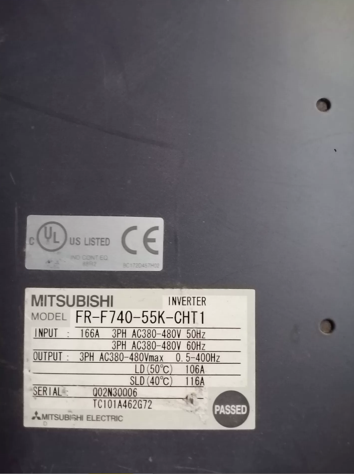



The FR-F740-S75K-CHT is a 3-phase 400V-class inverter from Mitsubishi Electric’s FREQROL‑F700 series, Diseñado específicamente para aplicaciones de ventiladores y bombas.. Optimizado para cargas de par cuadrático de 75 kW, Es un modelo emblemático clásico para sistemas industriales de control de velocidad y control de fluidos que ahorran energía., Cumple con la certificación CCC china y los estándares de red eléctrica nacional..
- Explicación del modelo
| Código | Descripción |
| FR | General prefix for Mitsubishi FREQROL series inverters |
| F740 | F700 series, 3-phase 380~480V class, energy-saving model dedicated for fans and pumps |
| S75K | Applicable motor rating: 75kW three-phase induction motor; S indicates large-size heavy‑duty series |
| CHT | Version exclusive to Chinese market, adapted to local power grid, compliant with GB and CCC |
- Key Rated Electrical Specifications
| Artículo | Especificación |
| Applicable motor capacity | 75kilovatios (three-phase induction motor) |
| Rated output capacity | 110kVA for both SLD / LD duty |
| Corriente de salida nominal | 144A (common for SLD light duty / LD heavy duty) |
| Overload capacity | SLD default: 110% corriente nominal para 60s, 120% for 3s at 40°C |
| LD heavy duty: 120% corriente nominal para 60s, 150% for 3s at 50°C | |
| Both feature inverse-time characteristics | |
| Input power specification | 3-fase CA 380~480V, 50/60Hz; allowable voltage fluctuation: 323~528V, frecuencia: ±5% |
| Output frequency range | 0.2~400Hz, rango de control de velocidad 1:100 (bajo control de vectores) |
| Estructura de protección | Tipo abierto IP00, debe instalarse en un recinto calificado |
| Método de enfriamiento | Refrigeración por aire forzado |
| Aprox.. peso | 35kilos |
| Reactor de CC dedicado | FR-HEL-H75K |
- Funciones principales & Características
- Control dedicado de ahorro de energía
Optimizado para cargas de par cuadrático como ventiladores y bombas.. El control de excitación óptimo incorporado y el modo de ahorro de energía logran hasta 30% Mayor eficiencia energética que el control V/F convencional..
- Control de precisión multimodo
Admite control V/F, control vectorial de flujo magnético avanzado, control general de vectores. Par estable a baja velocidad. Adecuado para suministro de agua a presión constante, sistemas multibomba, control de temperatura/flujo de aire de circuito cerrado. Funciones duales PID y de reposo/vigilia incluidas.
- Alta confiabilidad & Protección total
Protección integral: sobrecorriente, sobretensión, subtensión, sobrecalentar, sobrecarga, prevención de estancamiento, falla a tierra. Adaptable a las fluctuaciones de energía.. La vida útil diseñada de los condensadores y ventiladores principales supera 10 años.
- Comunicación rica & Expansión
Estándar RS485, Modbus RTU. Enlace CC opcional, Profibus-DP, Tarjetas DeviceNet para una integración perfecta en sistemas de automatización.
- Diseño fácil de usar
Standard FR-DU07 keypad: local start/stop, frequency setting, parameter tuning, fault monitoring. Parameters compatible with Mitsubishi inverter series.
- Aplicaciones principales
Primary: 75kW 3-phase 380V fans, zapatillas, compressors — industrial water supply/drainage, central AC water circulation, boiler ID/FD fans, climatización, water treatment aeration/booster systems.
Secondary: Transportadores, mezcladores, equipo de ventilación. Ideal for continuous operation requiring high efficiency, estabilidad, y larga vida útil.
- Instalación & Directrices de puesta en marcha
- Instalación: IP00 open type must be installed in a proper enclosure, vertically mounted with sufficient cooling space. Ambient temp: -10~+50°C. Avoid moisture, polvo, gas corrosivo, strong EMI.
- Alambrado: Main input R/L1, S/L2, T/L3 → power supply; output U, V, W → motor. Never reverse input/output. Use suitable circuit breakers and contactors. Recommended DC reactor FR-HEL-H75K to improve power factor and reduce harmonics.
- Modos de control: PU (teclado), external terminal, comunicación. Perform motor auto-tuning first. Set acceleration/deceleration time, PID, y niveles de protección en consecuencia.
- Toma de tierra: Conexión a tierra independiente y confiable, resistencia ≤10Ω. No comparta terreno con equipos de alta potencia..
- Fallos típicos & Solución de problemas
| Código de falla | Descripción | Comprobaciones principales |
| COE1 | Sobrecorriente durante la aceleración | Compruebe si el tiempo de aceleración es demasiado corto, Cortocircuito del motor/falla a tierra, o cargar atasco |
| EOV | Sobretensión del circuito principal | Verifique el voltaje de entrada alto, corto tiempo de desaceleración, o circuito de frenado inadecuado |
| EUV | Subtensión del circuito principal | Comprobar pérdida de fase, terminales de entrada flojos, o fluctuación excesiva de potencia |
| OH | Sobrecalentamiento del inversor | Verificar falla del ventilador, conducto de aire bloqueado, o temperatura ambiente excesiva |
| OL | Sobrecarga del motor | Comprobar calado del motor, sobrecarga, o parámetros nominales del motor no coincidentes |
Guía completa para la selección de resistencia de frenado para Mitsubishi FR-F740-S75K-CHT
- Notas críticas de preselección (Debe leer)
El FR-F740-S75K-CHT es un inversor de bomba/ventilador trifásico de 400 V y 75 kW sin transistor de frenado ni unidad de frenado incorporados.. It cannot directly connect external braking resistors.
An external braking unit must be installed first, then matched braking resistors. De lo contrario, permanent damage to the inverter main circuit will occur.
1.1 Typical Applications Requiring Braking Resistors
Fast motor deceleration / detener, much shorter than free-run time
High-inertia loads (grandes fans, zapatillas, centrífugas)
Frequent `EOV` DC bus overvoltage faults during deceleration
Precise speed control without overshoot
Continuous braking for hoisting / lowering applications
1.2 Recommended Braking Unit
Use genuine Mitsubishi or compatible units:
| Artículo | Genuine Model | Parámetros clave |
| unidad de frenado | FR-BU2-H75K | For 75kW 400V-class inverter, max withstand voltage 800V DC, IP00, refrigeración por aire forzado |
| Minimum allowable external resistance | 6.5Oh | Never use resistance lower than this value, otherwise IGBT will burn out |
| Genuine matching resistor unit | MT-BR5-H75K | Standard resistance 6.5Ω, adecuado para 10% ED duty, built‑in overheat protection |
- Braking Resistor Selection Rules
Core parameters: resistencia, potencia nominal, clase de voltaje.
2.1 Resistencia (R)
Must be ≥ 6.5Ω
Practical range: 6.5Ω ~ 20 Ω
2.2 Potencia nominal (PAG)
Braking resistors are intermittent duty. Selection depends on ED% (duty ratio).
Genuine MT-BR5-H75K: 65kilovatios, suitable for ED ≤10%.
2.3 Tensión soportada & Tipo
Clase de voltaje: ≥ 1000V DC
Preferred types:
- Corrugated stainless steel resistor — excellent heat dissipation, sobrecarga alta
- Aluminum-housed resistor — compact, low duty
- Genuine MT-BR5 — plug-and-play, protección térmica
- Duty-Based Selection Table
| Duty Level | Aplicación típica | ED% | Recommended R | Recommended P | Notas |
| Light basic | Occasional stop, decel ≥30s, ≤10 starts per shift | ≤5% | 6.8Ω~10Ω | 7.5kW~10kW | Basic overvoltage protection only |
| General | Normal fan/pump, inicios frecuentes, decel 10~30s | 5%~10% | 6.5Ω~7.5Ω | 10kilovatios~15kW | Más común, rentable |
| High‑frequency | High‑inertia fan/centrifuge, fast decel ≤10s | 10%~20% | 6.5Oh (estándar) | 15kilovatios~30kW | Enhanced cooling, parallel resistors |
| Continuo | Potential load, long‑term lowering | ≥20% | 6.5Oh (obligatorio) | ≥30kW (genuine 65kW preferred) | Independent thermal protection + enfriamiento forzado |
3.1 Genuine Complete Set
Unidad de frenado: FR-BU2-H75K
Resistencia de frenado: MT-BR5-H75K (6.5Oh, 65kilovatios)
3.2 Economic Compatible Types
Básico: RXLG 10kW 10Ω 1000V
General: RXLG 15kW 7.5Ω 1000V
Pesado: RXLG 30kW 6.8Ω 1000V (or two 15kW 13.6Ω in parallel)
- Alambrado, Instalación & Parámetros
4.1 Safety Wiring Rules
Secuencia: Inverter `P/+` → Braking Unit `P/+`; Inverter `N/-` → Braking Unit `N/-`; Braking Unit → Resistor.
Do NOT connect resistor directly to P/N.
Cable length ≤5m; max 10m for twisted pair.
Cable section ≥14mm², voltage rating ≥1000V.
Connect resistor thermal contact to inverter emergency stop.
4.2 Thermal Installation
Montar verticalmente, sufficient clearance, no enclosure blocking.
Keep ≥30cm from inverter and PLC.
For heavy duty: add forced cooling fan.
4.3 Key Inverter Parameters
| Número de parámetro. | Nombre | Configuración | Descripción |
| Pr.30 | Regenerative brake selection | 1 | Enable external braking unit |
| Pr.70 | Special regenerative brake | 0 | For FR-BU2 series |
| Pr.8 / Pr.11 | Accel / Decel time | Set by load | Avoid overload and overvoltage trip |
| Pr.150 | Overvoltage stall level | 660V | Match braking unit voltage |
- Fallos & Soluciones
| Síntoma | Comprobaciones principales |
| EOV overvoltage fault during deceleration | Loose resistor wire, faulty braking unit, excessive resistance, short decel time, incorrect parameters |
| Braking unit alarm / agotamiento | R < 6.5Oh, cableado invertido, resistor short, poor cooling |
| Resistor overheat / agotamiento | Under‑rated power, conexión floja, IGBT breakdown, insufficient cooling |
| Weak braking, long stopping time | Excessive resistance, wrong parameters, braking unit disabled |





NH42-63-318x560.png "Interruptores de transferencia automática tipo PC CHINT (ATS)NH42-63/4SZ")



