 contactor,cortacircuitos,sensor,Codificador,SOCIEDAD ANÓNIMA,Convertidor

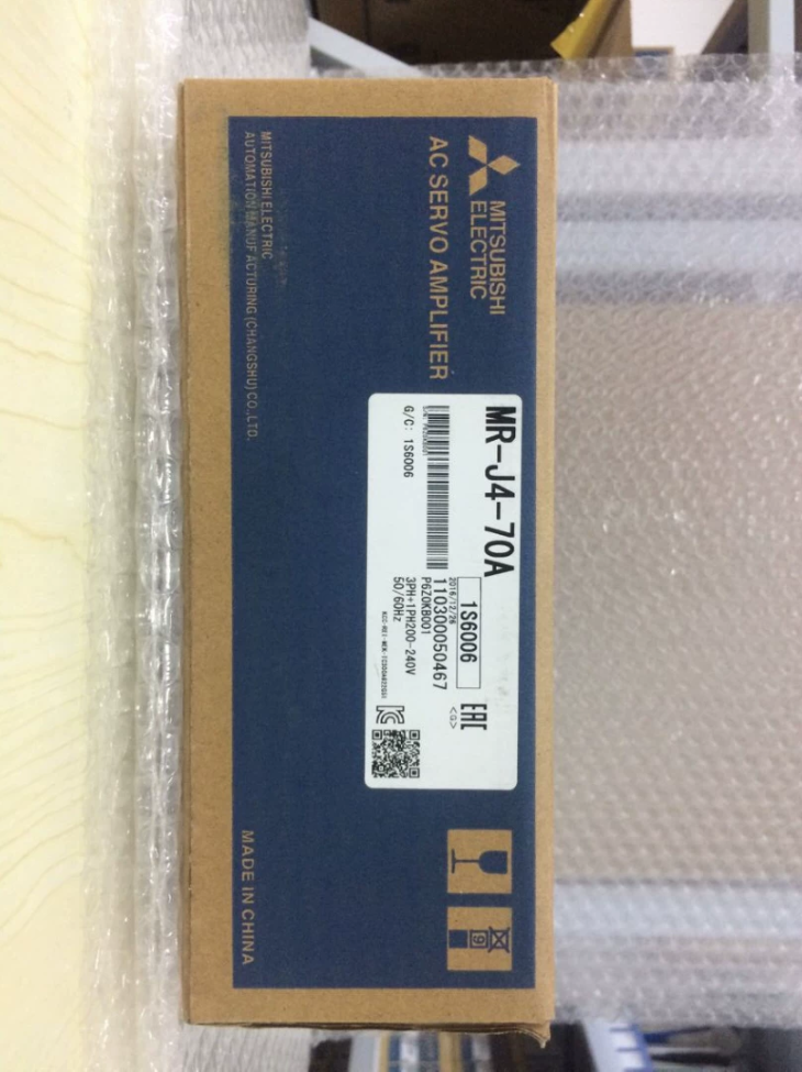

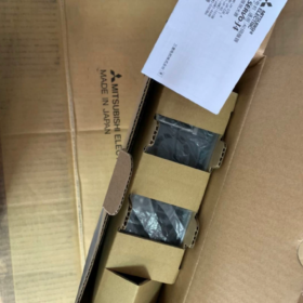
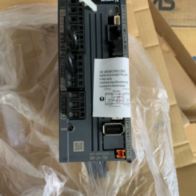
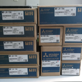
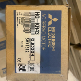
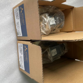
Serie MELSERVO-J4, 750W. (0.75 kilovatios), 200-Entrada de pulso de uso general clase V servoamplificador
Definición del modelo
Señor-J4: mitsubishi 4Serie de servos de cuarta generación
70: Potencia del motor adaptada: 750 W.
A: Interfaz de propósito general (legumbres + entrada analógica). No tipo bus de fibra SSCNET. Acepta comandos de pulso de SOCIEDAD ANÓNIMA. La variante -B está equipada con una interfaz de bus de fibra óptica SSCNET III/H..
Especificaciones eléctricas básicas
| Artículo | Especificación |
| Entrada de alimentación del circuito principal | Monofásico / Trifásico CA 200‑240 V, 50/60 Hz |
| Rango de entrada permitido | CA 170‑264 V |
| Corriente de salida nominal | 4.0 A; Corriente máxima: 12 A (1 s) |
| Controlar la fuente de alimentación | CC 24 V ±10 %, aprox. 0.5 A |
| Modos de control | Posición (máx.. pulso de entrada: 4 diputados), Velocidad, Esfuerzo de torsión |
| Función de seguridad | STO (Desconexión de par segura) |
| Componentes a bordo | Resistencia regenerativa incorporada, Freno dinámico |
| Software de configuración | MR‑Configurador2, Puerto de depuración USB |
Especificaciones mecánicas
Dimensiones: Ancho 60×Al168×P185mm
Peso: 1.4 kilos
Montaje: Vertical DIN-rail mounting inside cabinet, IP20
Temperatura de funcionamiento: 0-55 °C, sin condensación
Motores compatibles (Standard Combinations)
HG-KR73: 750 W., baja inercia, sin freno
HG-KR73B: 750 W., baja inercia, con freno electromagnético
HG-SR73: 750 W., inercia media
Nota: Amplifier and motor encoder must be matched. MR-J4 drives cannot directly run MR-J3 series motors.
Connector Overview
- CN1: Digital I/O signals, STO safety inputs
- CN2: Servo-motor encoder interface
- CN3: Legumbres / analog command input (for host PLC)
- CN4: USB debug port for PC parameter setup
- CN5: Analog monitor output
- UV/V/W: Power output to servo motor
Compatibilidad de reemplazo
- Upgrade within same product family
MR-J4-70A → MR-J5-70A (New-generation pulse-type servo). Hardware pin-out is incompatible; program retuning is required.
- Replacement for legacy unit
MR-J3-70A retrofit: MR-J4-70A offers functional compatibility, but mounting dimensions and wiring are not fully interchangeable; cables must be replaced.
- Bus-type comparison
Señor-J4-70A: Legumbres / analog interface; Señor-J4-70B: SSCNET fiber bus. Not direct pin-for-pin replacements.
Aplicaciones típicas
Engraving machines, etiquetadoras, material handling mechanisms, equipo de embalaje, machine-tool feed axes. Suitable for PLC systems with pulse-output capability.
Solución de problemas & Notas de mantenimiento
- ALM 32: sobrecorriente. Inspect U/V-W motor short-circuit or ground leakage.
- ALM 50: Sobrecarga. Check for mechanical jamming or poor inertia matching.
- AL.E6: Encoder communication failure. Inspect CN2 encoder cable.
- Regenerative overload: Frequent fast acceleration/deceleration requires external regenerative resistor.
Customs HS-code: 8501520000
Complete Installation Guide for Mitsubishi MR-J4-70A
⚠️Safety Warning: All wiring and disassembly must be performed with full power removed. Wait at least 15 minutes until the charge lamp extinguishes. Verify no high-voltage residual exists between P+-N- terminals with multimeter to avoid electric shock. El trabajo debe ser realizado por electricistas calificados..
Señor-J4-70A: 750 W., 200-V pulse-input servo amplifier, supports single-phase or three-phase AC200-240 V supply.
- Cabinet Mechanical Installation
1.1 Entorno de instalación
Montar verticalmente dentro del gabinete de control. NO lo coloque plano ni lo instale al revés.
Temperatura ambiente: 0-55 °C, sin condensación; Altitud ≤1000m; Libre de polvo, niebla de aceite y gas corrosivo.
Método de montaje: Fijación por tornillos o montaje en carril DIN.
1.2 Espacios libres de enfriamiento (Crítico)
Espacio libre superior ≥50 mm; Espacio libre inferior ≥50 mm; Espacio libre lateral ≥10 mm
Cuando se montan varios amplificadores uno al lado del otro, reservar suficiente espacio de refrigeración. Mantener alejado de componentes que generen calor, como contactores y resistencias..
No bloquee las rejillas de entrada y salida con cables o canalizaciones..
1.3 Procedimiento de fijación
- Asegúrese de que la placa posterior del gabinete esté plana y sin rebabas.
- Coloque el amplificador contra la placa posterior y apriete los cuatro tornillos de montaje..
- Evite impactos fuertes en la carcasa para evitar daños a los componentes internos..
- Cableado paso a paso
Definiciones de terminales para MR-J4-70A
L1, L2, L3: Main-circuit power input. For single-phase 220 V operation: connect L1 & L2; leave L3 unconnected.
L11, L21: Control-circuit power AC200-240 V
UV/V/W: Power output to servo motor
P+, N-: Regenerative resistor terminals; factory short-circuit jumper fitted for built-in resistor
educación física: Tierra protectora
CN1: Digital I/O and STO safety signals
CN2: Encoder plug for HG-KR73 / HG-SR73 motor
CN3: Pulse command I/O connected to PLC pulse output
CN4: Mini-USB debug port for MR-Configurator2 PC software
Paso 1: Tierra protectora (educación física)
Connect amplifier PE terminal and motor PE to cabinet protective earth busbar. Earth resistance ≤ 10 Ω. Perform earthing first.
Paso 2: Power-circuit Wiring
- Main-circuit power L1/L2/L3
Three-phase AC200-240 V: Wire L1, L2 y L3.
Single-phase AC200-240 V: Connect L1 and L2; L3 must remain open.
Install circuit-breaker and contactor upstream. Never feed mains voltage into U/V-W output terminals.
- Alimentación del circuito de control L11, L21: CA200-240V. Puede compartir suministro con el circuito principal..
Nota: El circuito principal y el circuito de control se pueden suministrar por separado.. Para depuración solo de señal, energizar solo L11/L21; El amplificador se enciende sin voltaje del motor principal..
- Configuración de resistencia regenerativa:
Servicio normal de arranque y parada: Conserve el puente de cortocircuito de fábrica entre P+-D para usar la resistencia regenerativa interna.
Aceleraciones/desaceleraciones rápidas y frecuentes: Retire el puente y coloque una resistencia regenerativa externa entre P+ y N-, seleccione la resistencia y potencia nominal correctas.
Paso 3: Cable de alimentación del motor U/V/W
Conecte el amplificador U-motor U; motor en V V; W-motor W uno a uno. NO intercambiar fases. No inserte el contactor, Condensador o supresor de sobretensiones entre el amplificador y el motor..
Motores con freno electromagnético: La bobina de freno requiere suministro independiente de 24 V CC.. Brake release logic shall be controlled via external relay. Do not power brake from servo drive.
Paso 4: Encoder Cable CN2
Use dedicated MR-J4 encoder cable. Fully insert CN2 connector and lock latch. Route encoder cable away from power cables. Avoid sharp bending or pulling. MR-J3 encoder cables are NOT compatible with MR-J4 drives.
Paso 5: Digital I/O CN1 & Pulse Interface CN3 (Position-pulse control)
- EM2 (Forced stop / parada de emergencia): Hardware safety signal. Hard-wire emergency stop for operational machines. Short-circuit only for temporary bench testing.
- SON (Servo-On), RES (Alarm reset), LSP (Forward stroke limit), LSN (Reverse stroke limit).
- CN3 pulse command: Select PULSE+SIGN format to match PLC output configuration.
Separate signal cables from power cables by ≥ 10 cm to reduce noise interference. Use shielded signal cables with single-end shield grounding.
Paso6: Debug Interface CN4-USB
Connect Mini-USB cable between PC and CN4. Install MR-Configurator2 software for parameter backup, JOG operation and alarm diagnostics.
- Mandatory Pre-Power-On Check-List (Perform with power OFF)
- Multimeter measurements:
No short-circuit between L1-L2-L3 and L11-L21.
Good insulation; no short-circuit phase-to-phase or phase-to-ground on U/V-W motor output.
No short-circuit across P+ and N- terminales.
- Wiring verification:
Confirm mains supply is NOT connected to U/V-W output terminals.
U/V-W phases correctly matched; encoder connector latched; PE earthing solid.
Regenerative resistor jumper / external resistor fitted correctly; brake wiring verified.
- Mechanical inspection:
Coupling securely tightened; no mechanical binding; no mechanical collision risk. Implement anti-fall protection for vertical axes.
- Safety loop: Emergency-stop circuit confirmed functional.
- Power-Up Sequence
- Keep personnel clear of moving mechanisms; position machine at safe location.
- Energize control power L11/L21 first. Confirm amplifier powers on without alarms.
- Close main-circuit power L1/L2/L3.
- If alarms appear: Troubleshoot according to alarm codes (AL 32 over-current, AL.E6 encoder error, AL 50 overload).
- Connect PC software and back-up factory parameter set.
- Debug workflow:
- Run low-speed JOG via software, verify motor rotation direction.
- Validate forward / reverse limit signals.
- Configure pulse format and electronic gear ratio to match PLC.
- Test positioning with small-volume pulse commands; gradually increase travel.
- Run full-cycle motion and execute One-Touch-Tuning for servo gain optimization.
- Errores comunes de instalación
- Single-phase supply: Do not connect voltage to L3 terminal.
- Applying AC220 V power to U/V-W will permanently destroy amplifier.
- Loose encoder CN2 connector causes intermittent AL.E6 encoder fault.
- Powering motor brake directly from servo drive results in brake-release failure.
- Insufficient cooling clearance leads to thermal alarm AL 51 under continuous operation.
- EM2 emergency-stop left un-wired prevents servo-on operation.
- Parallel routing of power and signal cables causes pulse noise and positioning loss.
- Mantenimiento
Periodically re-tighten terminal screws; keep cabinet dust-free. Export and save servo parameter files annually.
Storage conditions: -20 ~ +65 °C, sin condensación.
Complete Parameter Tuning Procedure for Mitsubishi MR-J4-70A
MR-J4-70A pulse-input servo amplifier. Tuning tool: MR-Configurator2 (Mini-USB cable connected to CN4).
⚠️Before tuning: Confirme que la máquina esté mecánicamente libre de atascos.; Mantenga al personal alejado de las piezas móviles.. Después de la modificación de parámetros, escribir parámetros en EEPROM para almacenamiento no volátil. Grupos de parámetros: PA-Parámetros básicos, Ganancia PB & Filtrar, Parámetros extendidos para PC, Parámetros de asignación de PD-I/O.
- Conexión de software & Preparativos
- Conecte el PC Mini-USB a CN4. Encendido del disco. Inicie MR-Configurator2, ir en línea, lea todos los parámetros y guarde el archivo de copia de seguridad de parámetros.
- Restablecimiento de fábrica (opcional): Desbloquear la protección contra escritura a través de PA19, realizar reinicio de parámetros, apague y encienda para que los cambios surtan efecto.
- Confirmar la identificación del motor: Verifique el motor conectado HG-KR73 / HG-SR73 se reconoce correctamente en la pantalla del monitor del software; sin alarma de falta de coincidencia del motor.
- Parámetros de control básicos (Modo de pulso de posición más utilizado)
Grupo PA (Parámetros de configuración básicos)
| Número de parámetro. | Nombre | Descripción | Configuración típica |
| PA01 | Selección del modo de operación | 1000 = Control de posición de pulso; 0001 = Velocidad; 0002 = par | 1000 (Posicionamiento de pulso) |
| PA13 | PLSS Command pulse input format | Match PLC pulse output format | Must match PLC configuration |
| 0100: PULSE+SIGN (Legumbres + Sign, más común) | |||
| 0001: CW/CCW dual‑pulse | |||
| 0002: A/B phase quadrature pulse | |||
| PA06 CMX | Electronic gear numerator | CDVCMX=Number of PLC pulses per motor revolutionMotor encoder resolution(4194304) | Calculated per mechanical setup |
| PA07 CDV | Electronic gear denominator | ||
| PA10 | INP In‑position range | Position‑complete output window, unidad: command pulses | 50‑200, adjust for accuracy requirements |
| PA11 | Command pulse filter | 0 for differential‑line driver input; set to 1 for open‑collector input | 0 (Differential signal) |
| PA19 | Parameter write inhibit | 0000: Full parameter modification permitted; enable write‑lock after commissioning | 0000 during debugging |
✅Electronic-gear example: Ball-screw lead 10 mm, direct motor coupling. Require 10000 PLC pulses per full motor rotation.
Encoder resolution: 4194304 (22-poco)
CMX/CDV = 4194304 / 10000 → CMX=4194304, CDV=10000
Nota de hardware: Entrada diferencial máx. 4Mpps; colector abierto máx. 200kpps. Utilice señalización diferencial para funcionamiento a alta velocidad..
- Parámetros de E/S digitales del grupo PD
- PD01-PD14: Asignación de terminales de entrada (CN1)
SON (Servo-On), LSP (Forward stroke limit), LSN (Reverse stroke limit), RES (Reiniciar), EM2 (parada de emergencia).
La parada de emergencia del hardware EM2 debe estar cableada. Conexión de cortocircuito permitida sólo para pruebas de banco temporales; nunca para equipos de producción.
- PD20-PD27: Asignación de terminales de salida: ALMA (Alarma), RD (Servo listo), INP (En posición completa).
- Encendido & Cuerpo de Derecho (No se requiere conexión PLC, validación del motor primero)
- Software → Operación de prueba → Operación JOG.
- Establecer velocidad baja 50-200r/min, avanzar y retroceder.
- Confirmar dirección de rotación. Si se invierte la dirección: invertir el ajuste de PA14 Selección de dirección de rotación.
- Compruebe si hay ruidos anormales, vibración y unión mecánica.
Complete la validación de JOG antes de conectar los comandos de pulso del PLC.
- Ajuste de ganancia de servo (Critical for vibration, overshoot and positioning time)
Three tuning methods for MR-J4: One-Touch Tuning (Recommended first-choice), Real-Time Auto-Tuning, Manual PB-parameter fine-tuning.
Método 1: One-Touch Tuning (Recommended for commissioning)
- Complete mechanical assembly with real-world load fitted.
- Software menu Tuning → One-Touch Tuning.
- Set target response level: 1-15
High-rigidity light-load machine: 8-12
Timing-belt / low-rigidity mechanism: 3-7
- Execute procedure; servo performs reciprocating test motion to estimate load inertia and auto-set gains and filters.
- Write result to EEPROM after completion.
- Run positioning cycles; evaluate vibration, over-shoot and acoustic noise.
Método 2: Real-Time Auto-Tuning
Set PA08 tuning mode to `_ _ _1`. Servo continuously estimates load inertia and dynamically adjusts gain during actual machine operation. Suitable for variable-load conditions.
Método3: Manual PB-Parameter Fine-Tuning (Refinar cuando el resultado de One-Touch no es satisfactorio)
| Parámetro | Nombre | Función |
| PB06 | Relación de inercia carga-motor | Inercia de carga / motor de inercia. Calculado automáticamente mediante ajuste con un solo toque; se puede ingresar manualmente. |
| PB07 | Ganancia del bucle de posición PG1 | Un valor más alto acelera el posicionamiento; ganancia excesiva causa oscilación |
| PB08 | Ganancia del bucle de velocidad VG1 | Determina la respuesta dinámica; más alto mejora el rendimiento del seguimiento |
| PB09 | Tiempo integral del bucle de velocidad VI | Un valor más pequeño fortalece la acción integral, aumenta la tendencia a oscilar |
| PB13 | Filtro de paso bajo | Suprime la resonancia mecánica de alta frecuencia |
| PB01 | Filtro adaptativo de supresión de vibraciones | Set1 para habilitar la supresión automática de resonancia |
Secuencia de sintonización manual: Primero ajuste los parámetros del bucle de velocidad, luego bucle de posición. Si se produce una oscilación, reducir inmediatamente los valores de ganancia; no aumentes la ganancia a ciegas.
Tabla de corrección basada en síntomas
- Vibración zumbante al estar parado: Reducir la ganancia del bucle de posición PB07; habilitar el filtro adaptativo PB01, configurar el filtro de muesca.
- Posición excesiva: Ganancia de bucle de posición inferior; aumentar el tiempo integral del bucle de velocidad.
- Respuesta lenta y tiempo de asentamiento prolongado.: Subir moderadamente PG1 y VG1.
- Ruido anormal de frecuencia fija: Utilice la función Machine Analyzer del software para escanear la frecuencia de resonancia y configurar el filtro de muesca.
- Límite, Inicio-Regreso & Parámetros de límite de par
- PA12 Límite de par: Rango0-100%. Establezca al 50 % durante la puesta en marcha para evitar daños por colisión mecánica..
- PC01-PC06: Parámetros de referencia; modo de regreso a casa, velocidad de referencia, velocidad de avance, valor de compensación de inicio.
- PC13, PC14: Umbrales de posición de límite suave (unidad: command pulses).
- Carga de parámetros / Descargar & Ahorro
- Después de la modificación, ejecutar Escribir en EEPROM en el software. Los cambios almacenados solo en la RAM se perderán al reiniciar.
- Subir: Leer los parámetros del servo y guardar el archivo del proyecto.. Para reemplazo de amplificador, descargue el archivo de parámetros guardado para una puesta en marcha rápida.
- Secuencia de prueba de puesta en servicio estándar
- cuerpo legal JOG; Confirmar la dirección de rotación y sin ataduras mecánicas..
- Envíe comandos de pulso de pequeño volumen desde PLC, verificar la distancia recorrida mediante el cálculo electrónico de la relación de transmisión.
- Movimiento alternativo de baja velocidad; comprobar si hay ruidos y vibraciones.
- Ejecutar ajuste con un solo toque.
- Ciclos de posicionamiento de velocidad media y velocidad máxima; monitorear el estado en posición, sobreimpulso y vibración residual.
- Prueba funcional de límites de viaje., parada de emergencia y reinicio de alarma.
- Después de la validación completa, guardar copia de seguridad completa de los parámetros.
- Fallos comunes de puesta en marcha
- El motor no gira, RD (Servo listo) salida encendida: comprobar hijo (Servo-On) señal, Lazo de parada de emergencia EM2 y configuración del modo de operación PA01.
- El motor gira pero la distancia recorrida es incorrecta: Verifique el formato de entrada de pulso PA13 y el cálculo de la relación de transmisión electrónica CMX/CDV.
- Vibración y ruido anormal durante el funcionamiento.: Ajuste incorrecto de la relación de inercia, ganancia excesiva, mechanical resonance. Prioritize One-Touch-Tuning plus Machine-Analyzer tool.
- AL 50 Overload alarm: Excessive load-inertia ratio, high mechanical friction, gain values too high.
- AL.E6 Encoder alarm: Damaged or poorly-seated CN2 encoder cable.
HS-code for customs: 8501520000





NH42-63-318x560.png "Interruptores de transferencia automática tipo PC CHINT (ATS)NH42-63/4SZ")



