 contactor,cortacircuitos,sensor,Codificador,SOCIEDAD ANÓNIMA,Convertidor

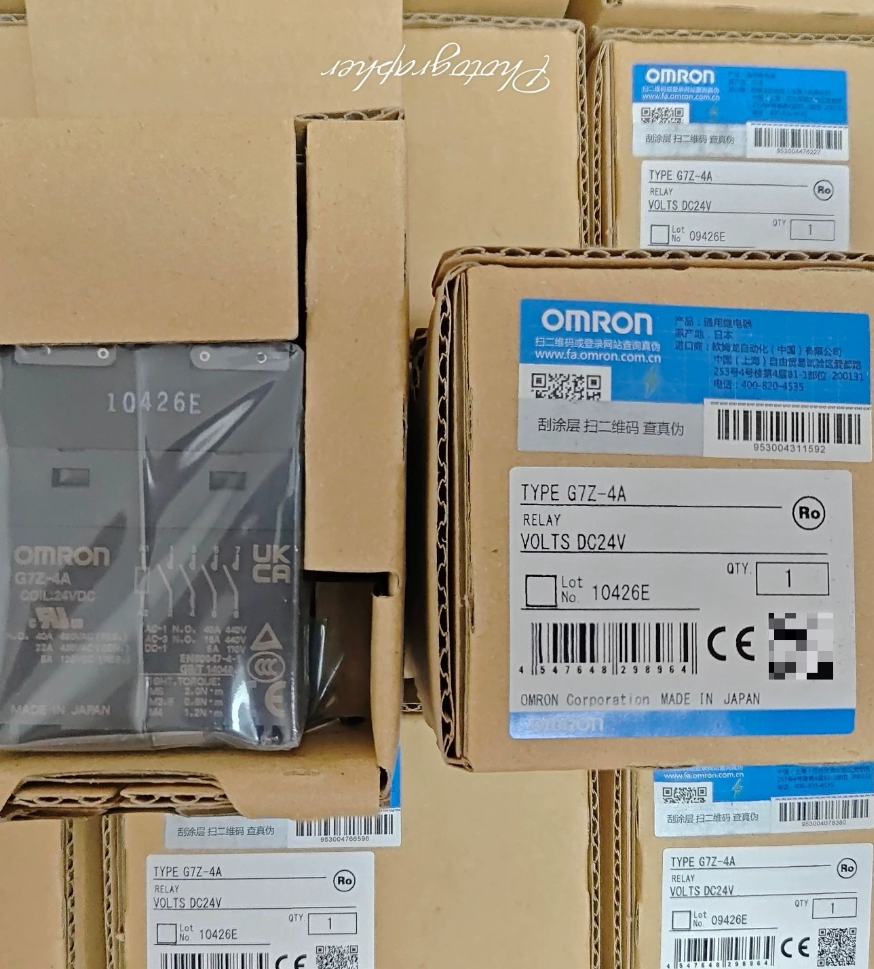

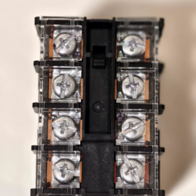
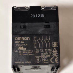
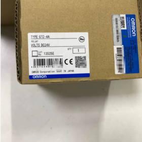
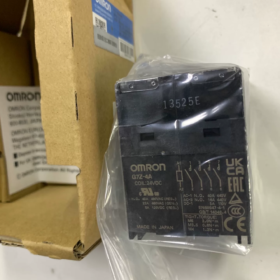
Serie: G7Z Multi-pole Relé de potencia (Compact Electromagnetic Contactor Type)
Definición del modelo:
G7Z: código de serie, high-power double-break relay
-4A: 4-pole Normally-Open (4a, 4PST-NO), no normally-open main contacts
Complete part numbers: G7Z-4A DC12/ G7Z-4A DC24; suffix -R denotes revised version; -11Z-R indicates fitted with 1a1b auxiliary contact block
Especificaciones eléctricas básicas
Bobina (DC driven)
| Parámetro | 12 V CC. | CC 24 V |
| Rated Coil Voltage | 12 V CC. | CC 24 V |
| Coil Current | 308 mamá | 154 mamá |
| Resistencia de la bobina | 39 Oh | 156 Oh |
| Operate Voltage | ≤75% of rated voltage | ≤75% of rated voltage |
| Release Voltage | ≥10% de la tensión nominal | ≥10% de la tensión nominal |
| Maximum Permissible Voltage | 110% | 110% |
| Consumo de energía de la bobina | ~3.7 W | ~3.7 W |
Contactos principales (4-pole NO, double-break structure, Ag-alloy contacts)
Carga resistiva: 40A @ AC440V; máximo. AC480V
Inductive load (cosφ=0.3): 22A @ AC440V
carga CC: 5A @ DC110V
máx.. Capacidad de conmutación: Resistive 17600 VA; Inductive 9680 VA
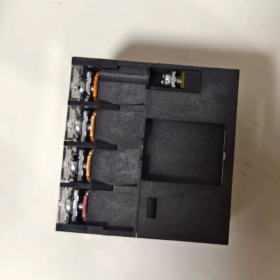
Terminales: Terminales de tornillo; Montaje: Montaje en carril DIN
Dimensiones: 80×100×100 mm; Luz indicadora de funcionamiento incorporada, vivienda cerrada
Variantes de modelo
- G7Z-4A DC12 / DC24: Unidad básica, 4 contactos NA principales, sin contactos auxiliares
- G7Z-4A-11Z-R DC24: Unidad principal 4a + bloque de contactos auxiliares 1a1b adjunto para señales de retroalimentación de estado
Los modelos heredados G7Z-4A-□Z están descontinuados; reemplazar con versiones con el sufijo -R: G7Z-4A-□Z-R
Aplicaciones típicas
Conmutación de cargas trifásicas de alta potencia de 380-440 V (calentadores, fuentes de alimentación, fans)
Instalación en carril DIN dentro de armarios de control, alternativa a los pequeños contactores; Unidad de salida CC PLC directa
⚠️ Nota: Consumo de energía de la bobina 3,7W; calcular el margen actual para los módulos de salida PLC. Reducir la corriente de contacto por encima de 40°C ambiente: reducir 0,7 A por aumento de 1 °C.
Opciones de reemplazo
- Omrón misma serie: G7Z-4A-xxZ-R (reemplazo actualizado de fábrica)
- Alternativa de contactor: 4-contactor de CA pequeño de polo (40 una clase, bobina de CC)
- Equivalente nacional: 4-Relé de potencia de carril DIN de bobina de polo 40A DC24V. Verificar las especificaciones clave: doble descanso, Clasificación AC440V, terminales de tornillo, consumo de energía de la bobina.
Puntos de control comunes para la resolución de problemas
- Verifique que el voltaje de suministro de la bobina sea ≥75% del valor nominal; medir la resistencia de la bobina para detectar bobinas quemadas
- Erosión del contacto principal: La vida útil cae drásticamente con cargas inductivas de 40 A.; utilizar un tamaño de contactor reducido como práctica preferida
- Mantenga una disipación de calor adecuada en entornos de alta temperatura para evitar una reducción de corriente insuficiente.
Instrucciones de montaje OMRON G7Z-4A
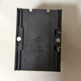
El G7Z-4A admite montaje en carril DIN y montaje con tornillos en panel.. Orientación de montaje obligatoria: terminales de la bobina mirando hacia arriba. Nunca lo monte con los terminales al revés.
- Montaje en carril DIN (Estándar para gabinetes de control)
Riel compatible: Norma DIN EN50022, 35×7,5 mm (TR35-15Fe) carril de acero
❗ No es compatible con rieles muy gruesos y resistentes de algunos fabricantes., riesgo de cierre inseguro.
Orientación de montaje: Instalación horizontal con terminales de bobina hacia arriba. Está prohibido el montaje vertical o invertido..
Procedimiento de instalación: Enganche el clip de resorte trasero en el borde superior del riel, presione hacia abajo hasta que un "clic" confirme el compromiso total.
Aseguramiento antivibración: Para entornos de alta vibración, Coloque topes de extremo de riel PFP-M en ambos lados para evitar deslizamientos o desplazamientos..
Eliminación: Haga palanca hacia abajo el clip de resorte inferior con un destornillador de punta plana y levante el relé hacia arriba..
- Montaje con tornillos en panel
Asegúrelo mediante dos tornillos M4 a través de los orificios de montaje en la carcasa. Par de apriete estrictamente 1,2-1,3N·m. Evite apretar demasiado (vivienda agrietada) o apretar poco (flojedad).
Mantenga los terminales de la bobina orientados hacia arriba..
Adecuado para gabinetes personalizados sin riel DIN estándar.
- Bloque de contactos auxiliares (G73Z-□Z-R) Asamblea & Eliminación
Los bloques de contactos auxiliares proporcionan información sobre el estado de la unidad base G7Z-4A:
- Inserte las garras del bloque en los huecos del cuerpo principal del relé.;
- Presione hacia adentro hasta que quede bloqueado con un clic audible.;
- Eliminación: Deslice el bloque auxiliar para desenganchar los ganchos y las garras.. No haga palanca con fuerza en los ganchos de plástico..
- Espacio libre de montaje & Requisitos térmicos (Crítico para la reducción de corriente)
- Mantenga un espacio libre mínimo de 5 mm entre la carcasa del relé y las superficies metálicas de tierra del gabinete en todos los lados.;
- Múltiples G7Z-4A uno al lado del otro: Mantenga un espacio mínimo de 30 mm entre unidades.. El montaje adyacente cercano provoca un calentamiento excesivo y una reducción obligatoria de los contactos.;
- Mantenga la zona superior bien ventilada; Evite apilar componentes que generen calor directamente encima.;
- Reducción de la corriente de contacto para temperaturas ambiente superiores a 40°C.
- Par de apriete de terminales
| Tornillo terminal | Par de apriete |
| Terminales de alimentación principales (M5) | 2.0-2,2 N·m |
| Terminales de bobina (M3.5) | 0.8-0,9 N·m |
Los terminales flojos causan sobrecalentamiento y desgaste bajo carga alta; Se recomienda el uso de una llave dinamométrica..
- Prohibiciones estrictas
- ❗ NO lo monte al revés (terminales hacia abajo): risk of abnormal mechanical operation and shortened service life.
- ❗ Do NOT mount rotated 90° on side.
- ❗ Do NOT use non-standard over-thick DIN rails.
- ❗ Do NOT touch live terminals while powered; fit terminal safety covers for shock hazard protection.
- Post-installation Checks
- Relay secured firmly without wobble (rail clip or mounting screws fully tightened);
- Auxiliary contact block is securely latched;
- All terminals torqued to specified values;
- Thermal clearances met; no obstructions surrounding the unit.
OMRON G7Z-4A Ambient Temperature Specifications
Temperatura ambiente de funcionamiento
-25 °C ~ +60 °C, sin glaseado, sin condensación.
40 A rated contact current applies at ambient ≤45 °C.
High-Temperature Current Derating Rule (Crítico)
For ambient temperature >45 °C up to 60 °C: reduce continuous allowable current by 0.7 A per 1 °C rise.
Example @50 °C: Max continuous current = 40-(50-45)×0.7 = 36.5 A
Example @60 °C limit: Max continuous current = 40-(60-45)×0.7 = 29.5 A
Same derating applies when G73Z-□Z-R auxiliary contact block is fitted.
Humedad ambiental
5 % ~ 85 % RH, sin condensación.
Temperatura de almacenamiento (Unpowered unit)
Not explicitly listed on datasheet; industrial practice: -40 °C ~ +70°C, sin formación de hielo ni condensación.
Design Notes
- Operation at -25 °C is permitted; prevent cabinet condensation; dehumidify cabinet before cold startup.
- Closely-mounted multiple units add self-heating; actual component temperature is higher than cabinet air-sensor reading. Adequate thermal spacing is mandatory.
- Coil resistance increases with temperature. Verify coil supply voltage maintains ≥75 % rated value under high-temperature conditions to prevent unreliable pull-in.
- No lo opere a una temperatura ambiente superior a 60 °C.: acelera la erosión de los contactos y el envejecimiento de la bobina.
Configuración de contactos OMRON G7Z-4A
Contactos principales de la unidad principal: 4a (4PST-NO), tetrapolar normalmente abierto; sin contactos principales normalmente cerrados
Explicación del código del modelo: 4A = 4 polos-Todo-NO. Todos los contactos se abren cuando la bobina está desenergizada.; Los cuatro polos se cierran simultáneamente al energizar la bobina..
Mecanismo de contacto: doble descanso. Dos puntos de quiebre separados por poste, capacidad mejorada de extinción de arco para conmutación de carga pesada de alto voltaje AC440V.
Material de contacto: aleación de AG.
Calificaciones de contactos principales (para poste)
Carga resistiva: 40 Un @ AC440V
Inductive load (cosφ=0.3): 22 Un @ AC440V
carga CC: 5 A @ CC 110 V.
Contactos auxiliares (Se requiere un bloque G73Z-□Z-R separado; no incorporado)
| Código de sufijo | Formulario de contacto auxiliar |
| -20Z-R | 2a (DPST‑NO, 2-polo NO) |
| -11Z-R | 1a1b (SPST‑NO + SPST‑NC, 1NO+1NC) |
| ‑02Z‑R | 2b (DPST‑NC, 2‐polo NC) |
Los contactos auxiliares utilizan una construcción de apertura única., max rated current 1 A. For status feedback signals only. NOT suitable for carrying main power loads.
Cross-reference for related series models (for selection reference)
- G7Z-4A:4a (4-pole NO)
- G7Z-3A1B:3a1b (3-pole NO +1-pole NC)
- G7Z-2A2B:2a2b (2-pole NO +2-pole NC)
Design Key Points
- G7Z-4A base unit has no main NC contacts. Select G7Z-3A1B / G7Z-2A2B if main normally-closed contacts are required.
- Double-break design provides high inter-phase withstand voltage; well-suited for switching 3-phase heaters and 3-phase fans.
- Auxiliary blocks are strictly for feedback signals; never use for power-carrying circuits.





NH42-63-318x560.png "Interruptores de transferencia automática tipo PC CHINT (ATS)NH42-63/4SZ")



