 contactor,cortacircuitos,sensor,Codificador,SOCIEDAD ANÓNIMA,Convertidor





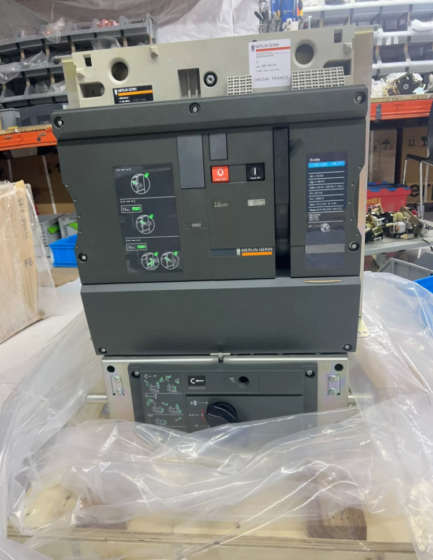
Nuevo Testamento: MasterPact NT series disyuntor de aire (ACB, modelo heredado, interrumpido; replacement model MTZ1 06H2)
06: Tamaño del marco 06, frame rated current 630A
H2: Breaking capacity class H2; Icu=50kA@440VAC, short-time withstand current Icw=50kA (1s), Class B selective protection
Parámetros eléctricos básicos
| Artículo | Especificación |
| Frame rated current In | 630A (a 40 ℃) |
| Tensión asignada de empleo Ue | CA 690V, 50/60Hz |
| Tensión nominal de aislamiento Ui | CA 1000V |
| Tensión nominal soportada al impulso Uimp | 12kV (1.2/50μs lightning impulse) |
| Capacidad máxima de corte en cortocircuito Icu | 50kA@440V; 42kA@690V |
| Número de polos | 3PAG / 4opcional |
| Tipo de construcción | Fijado / sorteo |
| Unidad de viaje | Frame supplied without trip unit, MicroLogic trip unit to be ordered separately |
| Estándares | CEI 60947-2, with isolating function |
Notas clave
- Estado de discontinuación: NT series scheduled for end-of-sale by the end of 2025. Replacement model MTZ1 06H2, part number LV947203 (draw-out version)
- Parameter Clarification
Ue=690V: Maximum normal operating voltage
Interfaz de usuario = 1000 V: Tensión soportada a frecuencia industrial
Uimp=12kV: Tensión soportada al impulso del rayo. NOT applicable for 12kV high-voltage switchgear, this is an insulation index for low-voltage ACB
- Solicitud: Incoming feeder, bus tie and heavy-load outgoing feeder in low-voltage distribution systems, for industrial plants, data centers and marine power distribution; supports selective protection and coordination with upstream/downstream devices
- Reference Frame Part Numbers
NT06H2 3P Fixed: 47113
NT06H2 3P Draw-out: 47203
NT06H2 4P Fixed: 47119
Accesorios & Piezas de repuesto
Trip Units: Micrológica 2.0 / 5.0 / 6.0 / 7.0 (sobrecarga, retraso breve, instantaneous and earth-fault protection)
Accesorios: Motor operating mechanism, contactos auxiliares, fault alarm contacts, closing coil, shunt trip coil, door interlock, phase barriers
Draw-out base: Mandatory independent cradle for draw-out version
Pautas para la solución de problemas
- No cerrar: Undervoltage coil de-energized, incomplete spring charging, cradle not in connected position, interlock blocking
- Unintended tripping: Check trip unit protection curve, falla a tierra, harmonic distortion and temperature rise
- Prueba de aislamiento: Power frequency withstand test at Ui=1000V level; 12kV impulse withstand is type-test only, no on-site 12kV impulse test
Domestic Alternative Reference
Domestic MT06H2 (Schneider domestic MT series). Compatible breaking capacity and mounting dimensions for direct replacement.
Schneider MasterPact NT06H2 Air Circuit Breaker Technical Manual (Full Engineering Version, per original datasheet 0613CT0001)
Observaciones: NT series is legacy discontinued ACB, frame size NT06, En=630A; breaking class H2; frame supplied without trip unit, MicroLogic trip unit to be ordered separately; standard IEC 60947-2, isolating function, Class B selective protection
Tabla de contenido
- Descripción general del producto & Explicación del código del modelo
- Parámetros eléctricos nominales
- Parámetros mecánicos, Dimensiones generales & Peso
- MicroLogic Trip Unit Selection
- Lista de accesorios & Secondary Terminal Definition
- Instalación & Requisitos de cableado
- Operación, Manejo & Interlock Description
- Mantenimiento, Inspección & Solución de problemas
- Condiciones ambientales
- Replacement Model Information
- Original Document Index
- Descripción general del producto & Explicación del código del modelo
1.1 Descripción general
MasterPact NT series low-voltage air circuit breakers for incoming feeders, bus ties and high-current outgoing feeders in 400/690V low-voltage distribution systems. NT06H2 maximum frame rating 630A, available in draw-out or fixed construction, spring charged operation, configurable with intelligent MicroLogic protection unit, supports remote signalling, metering and communication.
Important Reminder: Interfaz de usuario = 1000 V (tensión nominal de aislamiento), Uimp=12kV (lightning impulse withstand voltage). NOT 12kV high voltage circuit breaker, only for AC ≤690V low-voltage distribution.
1.2 Desglose del modelo
Nuevo Testamento: MasterPact NT series air circuit breaker
06: Tamaño del marco 06, frame rated current 630A
H2: Breaking class H2; Icu=50kA@440VAC, Icw=50kA 1s, Class B selective
Números de pieza:
NT06H2 3P Fixed: 47113
NT06H2 3P Draw-out: 47203
NT06H2 4P Fixed: 47119
1.3 Estado del producto
NT series scheduled end-of-sale by end of 2025; replacement model MTZ1 06H2, part number LV947203 (draw-out). Mounting dimensions and secondary interfaces fully compatible for direct replacement.
- Parámetros eléctricos nominales
| Artículo | Valor |
| Frame rated current In | 630A (at 40℃ ambient) |
| Tensión asignada de empleo Ue | CA 50/60 Hz, max 690V |
| Tensión nominal de aislamiento Ui | 1000V |
| Tensión nominal soportada al impulso Uimp | 12kV (1.2/50μs lightning impulse) |
| Capacidad máxima de corte en cortocircuito Icu | 50kA@440V; 42kA@690V |
| Rated short-time withstand current Icw | 50el, 1s |
| Rated service breaking capacity Ics | 100% de Icu |
| Selectivity class | Clase B (with short-time delay selective protection) |
| Isolating function | Complies with IEC60947-2 isolation requirement |
| Número de polos | 3PAG / 4opcional |
- Parámetros mecánicos, Dimensiones generales & Peso
3.1 Resistencia mecánica
Vida mecánica: 20,000 operaciones (no-load make/break)
vida electrica (400V, En): 10,000 operaciones
Spring charging: Manual charging / motor charging MCH optional
3.2 Dimensiones generales (3PAG, unidad: milímetros)
tipo fijo: W300 × H415 × D266
tipo extraíble (with cradle): W300 × H415 × D376
4P version width 360mm, height and depth unchanged
3.3 Peso
Fixed frame only: ≈32kg
Draw-out frame + cradle: ≈52kg
3.4 Three positions for draw-out version
- Connected Position: Main circuit and secondary circuit fully connected, normal operation
- Test Position: Main circuit disconnected, secondary circuit remains connected for protection test
- Disconnected Position: Main and secondary circuits fully disconnected, breaker can be withdrawn for maintenance
- MicroLogic Trip Unit Selection (Must be ordered separately, not included with frame)
| Modelo de unidad de disparo | Funciones de protección | Aplicación típica |
| Micrológica 2.0 | Long-time overload protection only | Aislador, overload-only protection |
| MicroLogic 5.0A | Long-time Ir, short-time delay Isd, instantaneous Ii | Incoming feeder, bus tie (más común) |
| MicroLogic 6.0A | All functions of 5.0A + protección de falla a tierra | Critical incoming feeder requiring earth fault protection |
| MicroLogic 7.0A | 6.0A + protección de corriente residual + monitoreo armónico | Centros de datos, sensitive loads |
Protection setting range: Y (mucho tiempo) 0.4~1×In; Isd short-time delay 0.5~10×In, delay 0.1/0.2/0.4s; Ii instantaneous 1~15×In.
- Lista de accesorios & Secondary Terminal Definition
5.1 Accesorios opcionales
- MCH: Charging motor AC220V / CC 24 V
- XF: Closing solenoid AC220V / CC 24 V
- MX: Bobina de disparo en derivación (apertura remota)
- Minnesota: Liberación de subtensión (MNu time-delayed undervoltage for auto-transfer application)
- DE: Contactos auxiliares (CB on/off status feedback)
- SDE: Fault trip contacts (signal for overload/short-circuit/earth fault trip)
- FP: Cradle position contacts (connected / test / disconnected position)
- Phase barriers, cabinet door interlock, mechanical interlock cables, padlock device
- ULP communication module: Modbus RTU, remote signalling & medida
5.2 Secondary Terminal Definition
| Código | Nombre | Terminales | Descripción |
| MCH | Charging motor | B1, B2 | Auto charging upon power-up; B1-B3 charged ready CH contact |
| XF | Closing coil | A1, A2 | Actuación de cierre |
| MX | viaje de derivación | C1, C2 | Remote opening |
| Minnesota | Liberación de subtensión | D1, D2 | Trip on loss of voltage, core component for auto-transfer |
| DE | Auxiliary position contact | 11-12 CAROLINA DEL NORTE /11-13 NO | On/off status feedback |
| SDE | Fault trip contact | 81,82 | Protection action signal |
| FP | Cradle position contact | 251/252/254 | Draw-out position signal |
- Instalación & Requisitos de cableado
- Montaje: Vertical upright installation, ±5° tilt allowed; inverted mounting prohibited
- Conexión del circuito principal: Conexión frontal / rear horizontal / rear vertical connection; apply specified tightening torque for copper busbars to avoid overheating
- Secondary control wiring: 0.75~1.5mm² multi-core shielded cable; independent AC220V/DC24V control power supply for secondary circuit
- Prueba de aislamiento: Power frequency withstand test at Ui=1000V level; 12kV impulse withstand is type test only, no on-site 12kV impulse test
- Draw-out operation: Use dedicated crank for rack-in / rack-out; prohibit racking out breaker from connected position under live condition
- Operación, Manejo & Interlock Description
7.1 Operation Procedure
- Charging: Manual charging handle or MCH motor auto charging; charging complete, charged indicator lights on
- Cierre: Local front panel close pushbutton / XF remote close; verify interlock conditions before closing
- Apertura: Local open pushbutton / MX remote opening / automatic protection tripping; after fault trip, fault reset button must be manually reset before re-closing
7.2 Entrelazar (Two-incoming one bus tie scheme)
Enclavamiento mecánico: Steel cable mechanical interlock, physically prevents simultaneous closing of three ACBs
enclavamiento eléctrico: Close circuit wired in series with normally closed contacts of other breakers for double protection
Cradle position interlock: Closing circuit blocked when not in connected position, closing prohibited
Fault trip interlock: Auto-transfer closing logic blocked upon SDE contact activation
- Mantenimiento, Inspección & Solución de problemas
8.1 Mantenimiento periódico
Semi-annual: Check charging status, on/off indication, contact temperature rise, tightness of secondary wiring
Anual: Dust cleaning, insulation inspection, trip unit test (using MicroLogic test cable)
Revisión (cada 5 años): Disassemble to inspect main contacts and arc chamber, mechanical lubrication, mechanical life verification
8.2 Solución de problemas típicos
- No cerrar
Incomplete charging; undervoltage MN coil de-energized; cradle not in connected position; interlock blocked; fault trip not reset
- Unintended tripping
Verify protection curve; falla a tierra; harmonic overload; loose wiring with overheating; voltage dip triggering MN undervoltage trip
- Charging failure
No power supply to MCH motor; jammed charging mechanism; damaged charged-ready contact
- No fault signal output
Wrong SDE auxiliary contact wiring, contactos quemados
- Condiciones ambientales
Temperatura ambiente de funcionamiento: -5℃ ~ +70℃; Se requiere reducción de potencia por encima de 40 ℃
Temperatura de almacenamiento: -40℃~+85℃
Humedad relativa: ≤95% (sin condensación)
Altitud: ≤2000m; derating and insulation correction required above 2000m
Grado de protección: Device IP30; IP40 with cabinet door closed
Grado de contaminación: 3
- Replacement Model Information
NT06H2 → MTZ1 06H2
Frame 630A, Uci=50kA, compatible MicroLogic trip unit
Dimensiones de montaje, primary busbar and secondary terminals fully compatible, no cabinet modification required for in-panel retrofit
Supports ECOSTRUXURE Power software commissioning, upgraded communication interface
Schneider MasterPact NT Full Series Model List (IEC Version, Discontinued ACB, Frame 630~1600A)
Regla de nomenclatura: Nuevo Testamento + Frame Code + Clase de ruptura
Frame Code: 06=630A; 08=800A; 10=1000A; 12=1250A; 16=1600A
Clase de ruptura: N1 / H1 / H2 / L1; Construcción: Fijado / sorteo; Poles 3P/4P; Frame without trip unit, MicroLogic to be ordered separately
Common Base Parameters: Interfaz de usuario = 1000 V, Uimp=12kV, Ue max AC690V, Class B selective protection
Breaking Class Definition (440V, Icu ultimate breaking capacity)
N1: 35el
H1: 42el
H2: 50el (same class as NT06H2)
L1: 130el (tipo de limitación de corriente, application for high short-circuit capacity)
NT Full Model List
| Marco | Frame In | Clase de ruptura | Modelo completo | Icu@440V | icw(1s) | Typical 3P Fixed Part No. |
| NT06 | 630A | N1 | NT06N1 | 35el | 35el | 47111 |
| NT06 | 630A | H1 | NT06H1 | 42el | 42el | 47112 |
| NT06 | 630A | H2 | NT06H2 | 50el | 50el | 47113 |
| NT06 | 630A | L1 | NT06L1 | 130el | 50el | 47114 |
| NT08 | 800A | N1 | NT08N1 | 35el | 35el | 47121 |
| NT08 | 800A | H1 | NT08H1 | 42el | 42el | 47122 |
| NT08 | 800A | H2 | NT08H2 | 50el | 50el | 47123 |
| NT08 | 800A | L1 | NT08L1 | 130el | 50el | 47124 |
| NT10 | 1000A | N1 | NT10N1 | 35el | 35el | 47131 |
| NT10 | 1000A | H1 | NT10H1 | 42el | 42el | 47132 |
| NT10 | 1000A | H2 | NT10H2 | 50el | 50el | 47133 |
| NT10 | 1000A | L1 | NT10L1 | 130el | 50el | 47134 |
| NT12 | 1250A | N1 | NT12N1 | 35el | 35el | 47141 |
| NT12 | 1250A | H1 | NT12H1 | 42el | 42el | 47142 |
| NT12 | 1250A | H2 | NT12H2 | 50el | 50el | 47143 |
| NT12 | 1250A | L1 | NT12L1 | 130el | 50el | 47144 |
| NT16 | 1600A | N1 | NT16N1 | 35el | 35el | 47151 |
| NT16 | 1600A | H1 | NT16H1 | 42el | 42el | 47152 |
| NT16 | 1600A | H2 | NT16H2 | 50el | 50el | 47153 |
| NT16 | 1600A | L1 | NT16L1 | 130el | 50el | 47154 |
Draw-out part number: agregar 10 to the last digit. Example NT06H2 3P Draw-out:47203; 4P fixed part number +6 (NT06H2 4P Fixed 47119)
Derivative Isolator Models (HA version)
NTxxHA: Aislador (without trip unit, IEC60947-3)
NT06HA / NT08HA / NT10HA / NT12HA / NT16HA
Compatible Trip Unit List (Universal for full NT series)
Micrológica 2.0: Long-time overload only
MicroLogic 5.0A: mucho tiempo + retraso breve + instantáneo (preferred for incoming / bus tie)
MicroLogic 6.0A: 5.0A + protección de falla a tierra
MicroLogic 7.0A: 6.0A + protección de corriente residual + harmonic measurement
Replacement Cross Reference Table (NT → MTZ1)
| Legacy NT Model | Replacement MTZ1 Model |
| NT06N1 | MTZ1 06N1 |
| NT06H1 | MTZ1 06H1 |
| NT06H2 | MTZ1 06H2 |
| NT06L1 | MTZ1 06L1 |
| NT08~NT16 follow same rule | MTZ1 08 /10 /12 /16 + rompiendo clase |
Selection Remarks
- NT series fully discontinued, not recommended for new projects; MTZ1 can be used for spare parts replacement for existing projects with compatible primary and secondary interfaces.
- L1 current-limiting type for systems with extremely high short-circuit current, mayor costo; H2 is preferred for normal incoming feeder and bus tie.
- Rated current can be derated within the same frame by changing current sensor inserts, p.ej. NT06 frame available with 400A/500A/630A sensors.





NH42-63-318x560.png "Interruptores de transferencia automática tipo PC CHINT (ATS)NH42-63/4SZ")



