 contactor,cortacircuitos,inversor solar,medidor electrico,baterias solares

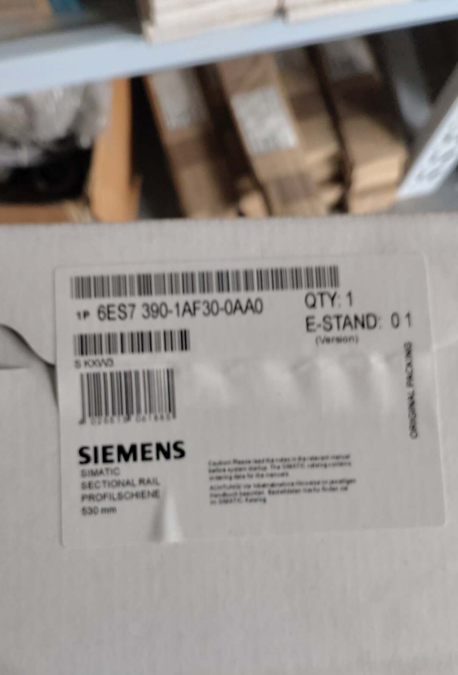

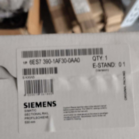
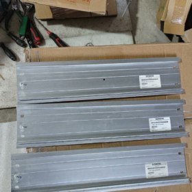
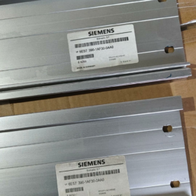
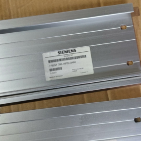
The 6ES7390-1AF30-0AA0 is a special profile mounting rail exclusively for siemens SIMATIC S7-300 series. Con una longitud total de 530 milímetros, it provides a unified mechanical mounting base, precise positioning and system grounding path for all S7-300 modules (UPC, fuente de alimentación, signal modules, módulos de funciones, communication processors, etc.). It serves as the fundamental structural carrier of S7-300 PLC systems.
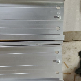
Fabricated from high-strength galvanized steel sheet, this rail is fitted with a standard grounding bolt for stable electrical conductivity. Unlike conventional 35 mm DIN rails, its dedicated groove design ensures secure engagement with module latches, preventing bus communication faults caused by poor contact. This model has reached the end of its product lifecycle. Spare units are still available through distributors, and it is widely used for maintenance, expansion and retrofitting of existing S7-300 systems.
Apariencia del producto
- Desglose del código del modelo
Número de pedido completo: 6ES7 390-1AF30-0AA0
- 6ES7: Prefix for product category, referring to Siemens SIMATIC S7 programmable logic controllers and accessories.
- 390: Sub-category, special profile mounting rails for S7-300 series.
- 1: Tipo de estructura, standard mounting rail with no extra special functions.
- AF30: Length code, corresponding to an overall rail length of 530 milímetros.
- 0AA0: Código de versión, standard industrial general version without custom features.
- Parámetros técnicos básicos
3.1 Mecánico & Dimensional Parameters
| Artículo | Especificación |
| Overall Rail Length | 530 milímetros |
| Usable Mounting Length for Modules | 480 milímetros |
| Overall Rail Height | 122 milímetros |
| Main Material | High-strength cold-rolled steel sheet with galvanized conductive and anti-corrosion coating |
| Peso neto | Aprox.. 1.0 kilos |
| Orificios de montaje | 4 fixing holes of φ6.5 mm, compatible with M6 mounting screws |
| Accesorios estándar | 1 set of M6 grounding bolt, end clamps for the first and last modules |
3.2 Eléctrico & Parámetros ambientales
| Artículo | Especificación |
| Método de puesta a tierra | Dedicated grounding bolt for equipotential bonding between rail, cabinet and system |
| Temperatura ambiente de funcionamiento | -25℃ ~ +60℃ |
| Almacenamiento / Transportation Temperature | -40℃ ~ +70℃ |
| Clase de protección | IP20 |
| Applicable Pollution Degree | Maximum Degree 3 |
| Altitud máxima de instalación | ≤ 2000 metro (Derating limit for modules; the rail itself has no altitude restriction) |
| Certificaciones | CE, UL, RoHS |
3.3 Adaptación & Parámetros de montaje
| Artículo | Especificación |
| Módulos compatibles | All standard S7-300 modules (PS power supply, UPC, SM signal modules, FM function modules, CP communication processors) |
| Capacity for Single-width Modules | Aprox.. 12 piezas (Residencia en 40 mm single-width modules; space occupied by double-width modules such as power supply and CPU shall be deducted) |
| Método de montaje | Vertically fixed to the rear panel of control cabinet with screws |
| Splicing Support | Multiple rails can be horizontally spliced. Grounding jumpers are required to ensure equipotential connection. |
| Cutting Support | The rail can be cut on site to shorten the length. Deburring and reworking for grounding continuity are required after cutting. |
- Modelos alternativos & Comparación de series completas
Product Lifecycle Notice
An official phase-out announcement (PM400 phase) has been issued for this model. The entire S7-300 series is gradually being discontinued. It is not recommended for new system design. Spare parts or compliant alternative products can be adopted for existing projects.
Full List of S7-300 Special Profile Mounting Rails
| Número de orden | Overall Length | Usable Mounting Length | Aplicación típica |
| 6ES7390-1AB60-0AA0 | 160 milímetros | 120 milímetros | Mini PLC systems with a small number of modules |
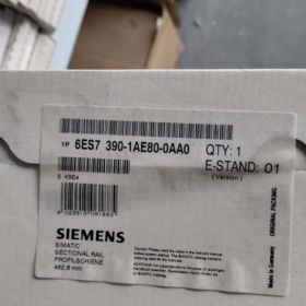
| 6ES7390-1AE80-0AA0 | 482.6 milímetros (19 pulgada) | 450 milímetros | Standard 19-inch cabinets, small and medium-sized systems |
| 6ES7390-1AF30-0AA0 | 530 milímetros | 480 milímetros | General small and medium-sized control systems (este modelo) |
| 6ES7390-1AJ30-0AA0 | 830 milímetros | 780 milímetros | Large racks and multi-module expansion systems |
| 6ES7390-1BC00-0AA0 | 2000 milímetros | Cut to required length | Long rail for on-site customized cutting |
Soluciones alternativas
- Same-brand Upgrade Replacement: There is no direct successor model with the same length. For new systems, migration to the S7-1500 platform with 6ES7590 series rails is recommended. Sin embargo, they are completely incompatible in mounting dimensions and module interfaces and cannot be directly replaced.
- Compatible Replacement for Existing Projects: Qualified third-party S7-300 dedicated mounting rails can be used. Verify groove dimensions and grounding conductivity before use. Original spare parts are recommended for high-reliability applications.
- Important Prohibition: Never use ordinary 35 mm DIN rails as a replacement. S7-300 modules adopt dedicated special latches at the bottom. Ordinary rails cannot fix modules reliably, which will cause severe faults including loose modules, poor contact of backplane bus and communication interruption.
- Supporting Accessories & Expansion Components
| Tipo de accesorio | Common Model | Descripción de la función |
| Backplane Bus Connector | Supplied with modules (U-type connector) | Establishes backplane bus data connection and internal power supply between adjacent modules |
| Rail Grounding Jumper | 6ES7390-0AA00-0AA0 | Ensures equipotential connection for spliced rails and reduces electromagnetic interference |
| Rail End Cover | 6ES7390-0BA00-0AA0 | Installed at both ends of the rail to prevent modules from sliding out and enhance safety protection |
| Shield Connection Kit | 6ES7390-5AA00-0AA0 | Grounds shielding layers of analog systems and improves anti-interference performance |
| Module End Clamp | Supplied with the rail | Secures the first and last modules to prevent displacement during operation |
- Escenarios de aplicación & Mounting Restrictions
Aplicaciones típicas
- Maintenance of Existing Industrial Systems: Spare part replacement, troubleshooting and partial expansion of existing S7-300 PLC systems in automotive, metalurgia, tratamiento de agua, maquinaria de embalaje, material handling and other industries.
- Small and Medium-sized Standalone Automation: Integration of S7-300 PLC systems for small machine tools, special-purpose equipment and test benches, suitable for control systems with 8 a 10 módulos.
- Standardized Cabinet Integration: Installation of PLC systems in standard industrial control cabinets, providing unified mounting reference and system grounding to standardize cabinet layout.
Requisitos de montaje & Operating Limits
- Dirección de montaje: Must be mounted vertically on the cabinet rear panel. Horizontal or inclined installation will impair module heat dissipation and latch reliability.
- Requisitos de conexión a tierra: Firmly connect the grounding bolt to the cabinet grounding bar with a grounding resistance ≤ 4 Oh. Poor grounding will weaken system anti-interference capability and lead to unstable communication.
- Splicing Rules: Align spliced rails closely without steps. Install grounding jumpers to avoid interference and surge damage caused by potential difference.
- Restricciones ambientales: For indoor installation inside control cabinets only. Outdoor exposure is prohibited. Avoid environments with high humidity, salt spray or corrosive gas, which will accelerate rail corrosion.
- Cutting Rules: Remove burrs after on-site cutting, and apply conductive and anti-corrosion coating on cut surfaces to guarantee continuous grounding.
- Fallos comunes & Matriz de solución de problemas
| Fenómeno de falla | Causa principal | Soluciones paso a paso |
| Module latches are loose and easy to shake or detach when pressed | 1. Non-original or non-standard rail with dimensional deviation in grooves | 1. Replace with original or qualified dedicated rail and verify groove dimensions |
| 2. Deformed rail caused by uneven mounting panel | 2. Straighten the mounting panel and retighten rail fixing screws | |
| 3. Aged or broken latches on module bottom | 3. Inspect module latches and replace damaged latches or modules | |
| Occasional bus faults, module drop-out and lit SF indicator | 1. Poor rail grounding leads to electromagnetic interference coupled into backplane bus | 1. Tighten grounding bolt, re-measure grounding resistance and ensure equipotential connection |
| 2. Misaligned modules causing poor contact of U-type backplane connectors | 2. Re-insert modules after power cut and confirm full engagement of U-type connectors | |
| 3. Displaced spliced rails leading to connector offset under module stress | 3. Realign spliced rails to keep the mounting surface flat | |
| Severe fluctuation and drift of analog data | 1. Poor rail grounding fails to release static electricity and interference | 1. Check grounding circuit and add extra shield grounding points |
| 2. Interference coupling due to parallel routing of power cables and signal cables | 2. Separate power cables and signal cables. Use shielded cables for analog signals with single-end grounding | |
| Mismatched mounting holes, unable to install the rail | 1. Wrong order number and mismatched length specification | 1. Check order number and length parameters, and replace with correct rail |
| 2. Deviated cabinet mounting holes | 2. Adjust cabinet holes or use elongated holes on the rail for fine positioning | |
| Severe rust and corrosion on rail surface | 1. Excessively high humidity or corrosive gas inside cabinet | 1. Install dehumidifier in cabinet to improve environmental conditions |
| 2. Damaged anti-corrosion coating during installation | 2. Polish lightly rusted areas and apply conductive paint; replace the rail if heavily corroded | |
| Uneven height of installed modules | 1. Steps at rail splicing joints | 1. Loosen fixing screws, realign rails and ensure flush splicing joints |
| 2. Poor flatness of mounting panel | 2. Straighten the rear panel and add more fixing points |
The 6ES7390-1AF30-0AA0 is a 530 mm special profile mounting rail dedicated to Siemens S7-300 series. There is no official direct replacement of the same length, as the entire S7-300 series is being phased out. Alternative solutions are classified into three categories according to application scenarios: original similar-length replacement for the same series, compatible replacement for existing maintenance projects, and upgrade & migration solutions for new systems. Ordinary 35 mm DIN rails are strictly forbidden for direct replacement.
- Directly Compatible Original Siemens Rails of the Same Series
All products below are dedicated special profile rails for S7-300. They feature fully compatible groove specifications, grounding structure and module latches with only different lengths, and can work with all standard S7-300 modules ideally for spare part replacement of existing projects.
| Número de orden | Overall Length | Descripción de reemplazo |
| 6ES7390-1AE80-0AA0 | 482.6 milímetros (19 pulgada) | Closest original model in length, compatible with standard 19-inch cabinets. Slightly fewer mounting positions than the 530 mm version, ideal for small and medium-sized systems with limited cabinet space. |
| 6ES7390-1AJ30-0AA0 | 830 milímetros | Long original rail, can be cut to 530 mm on site. Deburring and conductive anti-corrosion treatment are required after cutting. Suitable for systems reserved for future expansion. |
| 6ES7390-1BC00-0AA0 | 2000 milímetros | Full-length rail for arbitrary on-site cutting. Widely used for batch maintenance projects with lower average cost and sufficient stock. |
> Nota: All above models are at the end of product lifecycle. New units are still available via certain distributors for spare part selection.
- Compatible Third-party Replacement for Existing Maintenance Projects
For scenarios with insufficient original stock and cost control requirements, qualified domestic special profile rails for S7-300 can be adopted:
- Compatibilidad: Fully consistent with original products in groove size, mounting height and grounding hole positions, supporting non-destructive direct replacement and reliable latching of all S7-300 modules.
- Selection Requirements: Select products clearly marked as “S7-300 dedicated mounting rail”. Verify galvanized conductive coating thickness, grounding bolt specification and groove tolerance to avoid loose modules and poor backplane bus contact caused by dimensional errors.
- Solicitud: Replacement of rusted or deformed rails and additional rails for system expansion of existing facilities.
Strict Prohibition
Do not use ordinary 35 mm DIN rails for replacement. S7-300 modules are equipped with dedicated special latches on the bottom, which cannot be locked firmly by ordinary rails. This will result in serious failures such as module shaking and falling off, backplane bus disconnection and unexpected system shutdown. Ordinary DIN rails are only allowed for temporary commissioning, not for formal long-term engineering application.
- Actualización oficial & Migration Solution for New System Design
Siemens officially defines the S7-1500 series as the next-generation platform to replace S7-300, with corresponding 6ES7590 series mounting rails. Among them, 6ES7590-1AF30-0AA0 (530 milímetros) is the equivalent model with the same length.
Non-destructive direct replacement is impossible: S7-1500 rails differ completely from S7-300 in groove dimensions, module mounting method and backplane bus protocol. They must be used together with full sets of S7-1500 CPUs, signal modules and power supplies. This is a system-level migration solution rather than a simple single rail replacement.
Solicitud: Design of new automation projects and overall retrofitting of old systems. Not applicable to single rail replacement for existing projects.
Structural Difference: S7-1500 adopts standard 35 mm DIN rails, complying with universal low-voltage component mounting standards and offering higher flexibility for cabinet layout.
- Guidelines for Alternative Selection
- Rules for Cut Rails: Remove all burrs from cut surfaces and apply conductive anti-corrosion coating to ensure continuous grounding. Check module spacing after cutting to avoid interference with U-type backplane connectors.
- Grounding Reliability: Alternative rails must have good conductivity and be firmly connected to cabinet grounding bars with a grounding resistance ≤ 4 Oh. Poor grounding will reduce anti-interference performance and cause analog signal fluctuation.
- Rules for Spliced Rails: Align spliced rails closely without steps, and install dedicated grounding jumpers (6ES7390-0AA00-0AA0) to ensure equipotential connection.
- Lifecycle Suggestion: Avoid selecting S7-300 series rails for new project design. Prioritize products of the S7-1500 platform to guarantee long-term spare part supply and technical support.


 Impulse Heat-Sealing Temperature Controller")


")


NH42-63-318x560.png "Interruptores de transferencia automática tipo PC CHINT (ATS)NH42-63/4SZ")


