 contactor,cortacircuitos,sensor,Codificador,SOCIEDAD ANÓNIMA,Convertidor

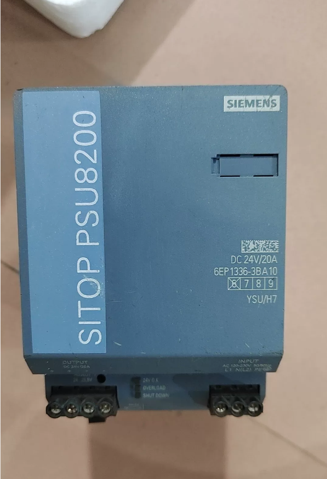

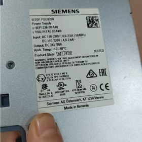
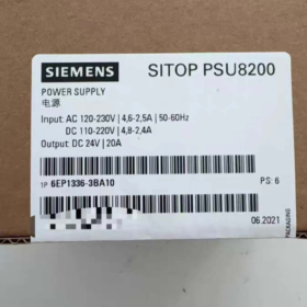
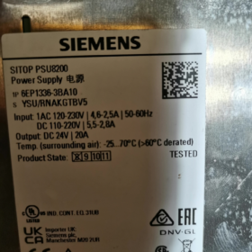
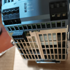
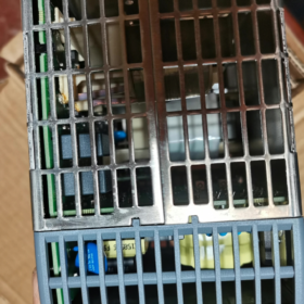
Nro. de orden: 6EP1336-3BA10
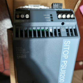
Designación completa: SITOP PSU8200 /1ACDC /24VDC /20A Fuente de alimentación industrial de modo conmutado de carril DIN
Producción: 24 VDC20A, 480 W.; Admite operación paralela para expansión de energía y operación redundante
- Especificaciones eléctricas básicas
Aporte (Entrada dual CA/CC exclusiva para este modelo)
Clasificación CA: 120-230 VACACIONES, rango de funcionamiento 85-275 VCA, 50-60 Hz
Clasificación CC: 110-220 VCC, rango de funcionamiento 88-350 VCC
Corriente de entrada: 2.5 Un @ 230 VCA; 4.6 Un @ 120 VCA
tiempo de espera: ≥20 ms con carga nominal
⚠️ Se requiere reducción de potencia cuando el voltaje de entrada <100 V
Producción
Nominal: 24 VCC / 20 A
rango ajustable: 24.0-28.8 VCC (Potenciómetro en el panel frontal para compensación de caída de tensión en cables largos.)
Función de aumento de potencia: Hasta 3 veces la corriente nominal (60 A) para cargas de irrupción como arranque de motor y relé; modo de corriente constante seleccionable o apagado enclavado en caso de cortocircuito
Salida aislada galvánicamente; protección contra cortocircuitos, sobrecarga, sobretensión y sobretemperatura; recuperación automática después de un apagado por sobretemperatura
Eficiencia: aprox. 93%-94%
Terminales de señal
- 24Contacto de relé V-OK (13-14): Contacto seco libre de potencial, cerrado cuando la fuente de alimentación funciona normalmente, para diagnóstico de estado del PLC
- Encendido/apagado remoto (15-16): Contacto libre de potencial para activación remota externa / desactivación de la salida de 24V
- Mecánico & Datos ambientales
Montaje: Montaje a presión en carril DIN estándar, carcasa metálica, refrigeración por convección natural sin ventilador
Dimensiones: Ancho 90 mm × Alto 125 mm × Fondo 125 mm
Peso: aprox. 1.2 kilos
Clase de protección: IP20 (solo para uso con montaje en gabinete)
Temperatura de funcionamiento: -25℃~+70℃; reducción de potencia por encima de 60 ℃; máximo. 75 % de carga a 70 ℃
Espacio libre de disipación de calor: Espacio libre superior de ≥50 mm & abajo; Las unidades se pueden montar firmemente una al lado de la otra.
Certificaciones: CE, UL/cUL, CCC, Aprobación marítima GL, RoHS
III. Evolución del modelo & Opciones de reemplazo
- Reemplazo directo del predecesor: 6EP1336-3BA00 (interrumpido)
6EP1336-3BA10 es una versión renovada por hardware, pin a pin, dimensión a dimensión, reemplazo directo compatible con funciones, con mayor eficiencia y rendimiento mejorado de bajo voltaje de entrada.
- Nuevo proyecto de la serie SITOP PSU6200 de nueva generación: 6EP3336-8SB00-0AY0
Nota: 6EP3336-8SB00-0AY0 solo admite entrada de CA, sin capacidad de entrada de CC. No compatible con hardware; las asignaciones de terminales difieren, prestar atención durante la selección.
- Módulos de extensión compatibles (Sistema modular PSU8200)
Directamente compatible con complementos modulares SITOP sin adaptadores adicionales:
módulo de búfer: 6EP1961-3BA21; Módulo ininterrumpible DC-UPS
Módulo de redundancia: 6EP1961-3BA00; para suministro redundante de doble potencia
Módulo de selectividad: 6EP1961-3BA31, protección limitadora de corriente de rama multicanal de 24 V; un cortocircuito en una rama no colapsará toda la barra colectora de 24 V
- Escenarios de aplicación típicos
Armarios de control PLC, robótica, maquinas herramientas, puerto & equipo marino, automatización de procesos. Ideal para sistemas que requieren entrada dual CA/CC (p.ej. suministro de CC de respaldo), altas cargas de irrupción, retroalimentación del estado de energía y control remoto de encendido/apagado.
- Pautas de cableado
- Terminales de entrada: L1, norte(L2), educación física; Soporta CA monofásica., grifo bifásico de red trifásica, o entrada CC
- Producción: Juegos dobles de terminales de tornillo para +24 V y 0 V. Paralele ambos conjuntos cuando la corriente de salida sea> 15 A para compartir corriente y prevención térmica.
- Terminales de señal: 13-14 comentarios de estado; 15-16 encendido/apagado remoto; ambos son contactos libres de potencial, no conecte circuitos de alto voltaje
- El voltaje de salida predeterminado de fábrica es 24 V.. Ajuste a 26-28 V para compensación de caída de cable largo; no exceda el voltaje soportado del equipo aguas abajo.
Instrucciones de montaje para siemens 6EP1336-3BA10 (PSU8200-20A)
- Tipo de montaje
Montaje estándar: Cumple con el carril DIN EN60715 (TS35-7.5 / TS35-15, 35 carril mm) instalación a presión
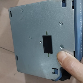
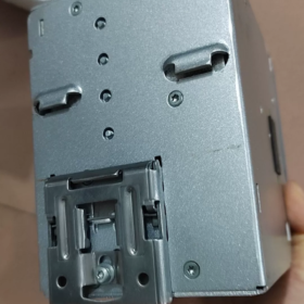
Clip de resorte incorporado en la parte trasera, montaje sin herramientas. Palanca de liberación en la parte inferior; Empuje la palanca hacia abajo para retirar la unidad del riel..
❌ NO se admite el montaje en pared mediante fijación directa con tornillos.. Montaje en carril DIN únicamente.
Grado de protección IP20, solo para instalación en gabinete interior; no apto para implementación en campo abierto al aire libre.
- Orientación de montaje (Obligatorio para el rendimiento térmico. & vida útil)
Convección natural sin ventilador; La orientación no se puede cambiar arbitrariamente.
- Posición estándar: montaje vertical, terminales hacia abajo (aporte & terminales de salida en la parte inferior de la unidad), unidad en posición vertical. Esta es la única posición oficial para operación continua a plena carga..
- ❌ Prohibido: montaje lateral horizontal, Al revés (terminales arriba), montaje inclinado. Las orientaciones no estándar degradan la refrigeración y requieren una reducción de carga pesada; no recomendado para implementación en campo.
- Requisitos de espacio libre térmico (Crítico)
| Dirección | Autorización requerida | Observaciones |
| Arriba | ≥50 mm | Permitir el flujo de aire caliente hacia arriba; las canalizaciones de cables no ocuparán este espacio |
| Abajo | ≥50 mm | Entrada de aire frío; la canalización no bloqueará el área inferior |
| Izquierda / Bien | 0 milímetros | Se pueden instalar varias unidades muy juntas, no se requiere espacio de lado a lado |
No monte componentes que generen calor directamente encima de la fuente de alimentación.. Reducir la carga cuando la temperatura ambiente del gabinete es >60 ℃.
- Montaje & Procedimiento de eliminación
- Enganche el pestillo superior del clip de resorte trasero en el riel DIN.
- Presione la sección inferior hacia el riel hasta que un "clic" audible confirme el acoplamiento del clip..
- Agite suavemente para verificar un asiento firme contra el aflojamiento por vibración..
- Eliminación: Empuje hacia abajo la palanca de liberación negra en la parte inferior., girar la parte inferior hacia afuera, levantar la unidad del riel.
Para entornos de alta vibración: Coloque topes finales en carril DIN para evitar el desplazamiento deslizante..
- Cableado de terminales & Valores de par
Realizar el cableado con la alimentación desconectada..
Entrada L/N/PE: 0.2-4 conductores mm², par de apriete 0,5-0,6N·m
Salida +24V /0V: Pares de terminales duales; paralelo a ambos pares para corrientes > 15 A para mitigar el calor
Terminales de señal 13-14 (Aceptar comentarios), 15-16 (Encendido/apagado remoto): 0.14-1.5 alambres finos mm², par 0,5-0,6N·m
- Montaje para paralelo / Módulos de redundancia
Esta fuente de alimentación se puede instalar lado a lado firmemente en un carril DIN con módulos de extensión SITOP compatibles. (redundancia, buffer, módulos de selectividad). No se necesita espacio térmico de lado a lado entre la fuente de alimentación y los módulos adicionales.
- Prohibiciones de montaje
- No instale la unidad dentro del canal inferior cerrado del gabinete.; El espacio libre superior/inferior bloqueado provoca un apagado por sobretemperatura..
- Prohibir la instalación al revés u horizontal.
- No coloque dispositivos que requieran mucho calor directamente encima de la unidad..
- Uso exclusivo del gabinete interior; Evite ambientes desprotegidos al aire libre y con mucha humedad..
6EP1336-3BA10 (PSU8200-20A) Paralelo / Directrices de redundancia + Lista de verificación de solución de problemas
- Operación paralela para expansión de energía (Sin aislamiento de fallas)
máx.. 5 Unidades idénticas en paralelo para compartir corriente automáticamente.. El interruptor DIP A debe estar en ON para activar la curva característica paralela.
- Requisitos previos de hardware: Número de pedido idéntico 6EP1336-3BA10; Mantenga las revisiones de hardware consistentes si es posible..
- Requisitos de cableado
Conecte +24 V y 0 V de cada unidad a la barra colectora de salida común.. Los cables positivos deben tener longitud y sección transversal idénticas para ecualizar la impedancia y compartir la corriente de forma adecuada..
Todos los terminales negativos de 0 V deben estar conectados a tierra.; No se permite terreno flotante..
Disyuntor de entrada común recomendado para arranque-paro sincronizado.
Diferencia de voltaje de salida sin carga entre unidades individuales ≤50mV (El valor predeterminado de fábrica cumple con los requisitos.; recalibrar si los potenciómetros han sido ajustados).
- Configuración del interruptor DIP
A-ON: Modo paralelo (para expansión de energía)
A-APAGADO: Modo de unidad única (predeterminado de fábrica; NO lo deje APAGADO para operación en paralelo)
- Limitación: El paralelo directo para la expansión de energía no puede aislar fallas. Un cortocircuito en una salida provocará la caída de toda la barra colectora de 24 V.. No apto para redundancia tolerante a fallos.
- 1+1 Suministro redundante (Aislamiento de fallas, Solución de ingeniería recomendada)
Dos unidades PSU8200-20A más módulo de redundancia 6EP1961-3BA00 (PSE202U) para aislamiento de desacoplamiento. Si falla una fuente de alimentación, el segundo se hace cargo de la carga sin problemas y sin interrupción del bus de 24 V.
- Diseño de carril DIN: Dos fuentes de alimentación + módulo de redundancia montado muy adyacente; terminales todos boca abajo; no se requiere espacio libre de lado a lado.
- Cableado de puntos clave
- Alimente dos fuentes de alimentación desde circuitos de entrada independientes para una máxima confiabilidad de redundancia.
- Conecte la salida de 24 V+ de cada fuente de alimentación a los dos canales de entrada del módulo de redundancia.
- Conecte de manera confiable los terminales de 0 V de las fuentes de alimentación y del módulo de redundancia para una conexión equipotencial; este paso es obligatorio.
- Enrute la salida del módulo de redundancia a la barra colectora de carga de campo de 24 V.
- El módulo de redundancia proporciona contactos de relé de falla., conectar a la entrada digital del PLC para alarma de fallo de redundancia.
- Configuración del interruptor DIP: Para configuración redundante, poner el dip-switch A de las fuentes de alimentación en OFF (modo de unidad única). NO active el modo paralelo.
⚠️ Nunca implemente redundancia por paralelo directo sin módulo de redundancia. El cortocircuito interno de una unidad provocará la caída de todo el sistema de 24 V..
III. Tabla de referencia de indicadores LED
| Estado del LED | Significado | Acción |
| Verde fijo encendido | Unidad saludable, salida>20V | funcionamiento normal |
| Amarillo fijo encendido | Sobrecarga / límite de corriente constante activo, Power‑Boost activado | Comprobar la corriente de carga; localizar un cortocircuito parcial; reducir la carga |
| Rojo fijo encendido | Apagado enclavado (cortocircuito / sobretensión / sobre temperatura) | Apagado durante ≥60 segundos, o anule la afirmación del control remoto 15‑16 durante ≥5 segundos para restablecerlo; eliminar el cortocircuito / causa raíz del sobrecalentamiento |
| Todos los LED apagados | Sin suministro de insumos; fusible interno fundido | Verifique el voltaje de entrada CA/CC y la conexión a tierra PE |
Interruptor DIP B: Selección de respuesta de cortocircuito
B-APAGADO (predeterminado de fábrica): Modo de corriente constante, 23 Una limitación de cortocircuito; recuperación automática después de que se borra la falla; LED amarillo encendido
B-ON: Modo de apagado enclavado; La salida se corta en caso de cortocircuito.; LED rojo encendido; se requiere reinicio del ciclo de energía
- Lista de verificación de solución de problemas
- Sin indicación LED después del encendido, salida cero
- Medir el voltaje de entrada L-N: CA 85-275 VCA / CC 88-350 VCC; confirmar la conexión a tierra de protección PE.
- Verifique el torque del terminal de tornillo para detectar contactos sueltos; verificar el estado del interruptor automático aguas arriba.
- Si el voltaje de entrada es normal pero no hay luces LED: Fallo del fusible de entrada interno; falla de hardware, reemplazar la fuente de alimentación.
- LED amarillo fijo encendido, la salida cae a 18-20V
- La corriente de carga supera los 20 A → modo de limitación de corriente constante; medir la corriente de carga total real.
- Cortocircuito parcial o daños en el aislamiento del cable en el lado de salida. Desconecte todas las cargas; compruebe si el voltaje se recupera a 24 V en condiciones sin carga.
- Caída excesiva de voltaje causada por cables de calibre delgado de larga distancia; utilice conductores de salida de mayor tamaño o aumente ligeramente el voltaje de salida mediante un potenciómetro para compensación.
- Apagado con enclavamiento del LED rojo al encender, sin salida
- Cortocircuito en el lado de salida. Prueba con todas las cargas desconectadas; El comportamiento normal sin carga indica un cortocircuito en la carga externa..
- Temperatura ambiente excesiva del gabinete, Espacio libre de ventilación superior/inferior insuficiente que activa la protección contra sobretemperatura; confirmar ≥50 mm arriba & espacio libre inferior.
- Sobretensión de salida: Asegúrese de que el potenciómetro no se ajuste accidentalmente por encima de 28,8 V; confirmar la clasificación de resistencia de voltaje del dispositivo aguas abajo.
- Procedimiento de reinicio: Apague ≥60 s y luego vuelva a energizar; o abrir Remoto 15-16 durante ≥5s y luego cerrar nuevamente.
- Anormal 24V-OK (13-14) comportamiento del contacto de relé
Terminales 13-14 son contactos secos libres de potencial, cerrado sólo cuando la salida>20V. Calificación de contacto: CC 30 V., máximo. 0.1 A. Sólo para señal de entrada digital de PLC; NO maneje bobinas de contactores ni cargas de alta potencia..
- Pobre reparto de corriente en paralelo; una unidad se calienta excesivamente
- Dip-switch A no puesto en ON.
- Gran discrepancia en longitud. / sección transversal de los cables de salida positivos.
- Diferencia de voltaje de salida sin carga> 50 mV entre unidades; potenciómetros de ajuste fino para hacer coincidir.
- Cableado suelto de 0 V que provoca una falta de coincidencia equipotencial.
- Terminales remotas 15-16 fallar en / fuera de control
15-16 son contactos libres de potencial: Cortocircuito = habilitación de salida; open-circuit = output disable. No external supply required.
If remote function is unused: Keep 15-16 short-circuited with factory jumper; do not remove jumper.
- Commissioning Recommendations
- New cabinet commissioning: Power-on without load first; confirm 24 V output and steady green OK LED; connect loads incrementally.
- Redundancy-system commissioning: Disconnect one input source at a time; verify seamless switch-over with zero load dropout.
- High-temperature cabinet applications: Apply load derating above 60 ℃ ambient; avoid continuous full-20-A operation.





NH42-63-318x560.png "Interruptores de transferencia automática tipo PC CHINT (ATS)NH42-63/4SZ")



