 Contacteur,disjoncteur,capteur,Encodeur,API,Convertisseur

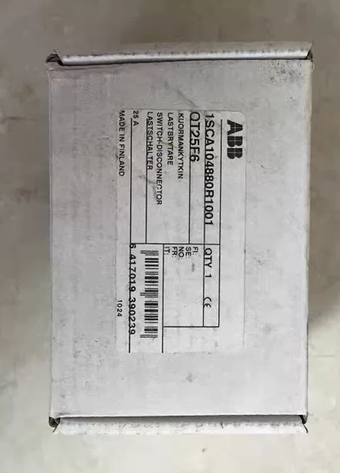

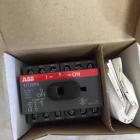
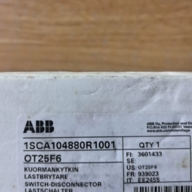
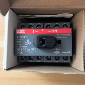
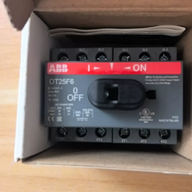
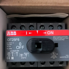
Numéro de commande: 1SCA104880R1001, Fabriqué en Finlande. La poignée et la tige ne sont PAS incluses; les accessoires de fonctionnement doivent être commandés séparément.
Explication du code modèle
OT: OT-series load-break switch-disconnector
25: Rated operational current 25 A
F: Front-operated; compatible with base-screw mounting and DIN-rail mounting
6: 6-pôle (6P.)
Spécifications électriques de base
| Article | Paramètre |
| Nombre de pôles | 6P. |
| Courant assigné d'emploi Ie (AC‑21A) | 25 UN |
| Courant thermique conventionnel Ith | 32 UN |
| Tension assignée d'isolement Ui | 750 V CA |
| Tension de tenue aux chocs Uimp | 8 kV |
| Terminaux | Protected clamp terminals; copper conductor 0.75‑10 mm² |
| Endurance mécanique | 20 000 operations |
| Indice de protection | Front IP20 |
| Short‑circuit withstand (with 25 A fuse) | 50 kA |
| HS code | 85365080 |
Dimensions mécaniques
Width × Height × Depth: 70 × 68 × 68 mm. Incoming/outgoing cables can be wired top-in-bottom-out or bottom-in-top-out.
Montage & Accessoires
- Options de montage: DIN35 rail clip-on mounting + base screw fastening
- ⚠️Handle and operating shaft are not supplied with the base unit. Handle assemblies (par exemple. OHS series) must be purchased separately for operation; door-mounted external operation is supported.
- Auxiliary contact blocks (OA1G series) can be fitted as optional add-ons.
- Padlockable in OFF position for safe maintenance isolation.
Applications typiques
Multi-circuit AC/DC isolation for PV combiner boxes, energy-storage systems and UPS
Maintenance disconnector inside control cabinets for frequency converters and soft-starters
6-configuration des pôles: 3-phase + 3-DC-circuit isolation, dual 3-phase isolation scenarios
Équivalent & Replacement References
Original ABB: Only OT25F6 base unit; Do not confuse with OT25FT6 (FT = door-mount type)
Référence alternative nationale: CHINT NH2-25-6P, Delixi 6P-25A disconnector (verify mounting dimension and terminal capacity before substitution)
Pièges courants
- OT25F6 is delivered as base unit only. No handle is provided; direct manual actuation is impossible. Handles are frequently omitted in project ordering.
- Do not mix F (base / Montage sur rail DIN) and FT (door-mount) variantes. They are mechanically non-interchangeable.
- Current derating is required for motor-load operation under AC-23A utilization category.
Operating Instructions for ABB OT25F6 (OT-Series) Switch-Disconnector
⚠️Important note: OT25F6 base unit is fitted with a square drive shaft bore only. No handle or shaft is factory-fitted. OHS / OHB handle assemblies must be installed before operation. Never turn the bare shaft bore directly.
Two Handle Types
- Internal cabinet direct handle (OHS): Mounted on the front face of the switch body for operation inside the enclosure.
- External door-mount handle (OHB / OHYS): Used with extended square shaft; handle fitted to cabinet door surface. Equipped with door-interlock: Cabinet door cannot be opened when switch is ON (energized state). Door can only be opened when switch is switched OFF.
Standard Manual Close / Open Operation
Close (SUR, energize circuit): Rotate handle clockwise until an audible “click” locks the mechanism. Align handle marker to I / ON position to ensure full contact closure.
Ouvrir (DÉSACTIVÉ, isolate circuit): Rotate handle counter-clockwise until an audible “click” locks the mechanism. Align handle marker to 0 / OFF position to establish safe isolating gap.
✅Always rotate to full locked position. Intermediate positions will cause poor contact and overheating.
CŒUR (Lockout-Tagout) for Maintenance
Locking is only possible at the OFF position (locking in ON position is not supported).
- Turn handle fully to OFF position.
- Flip up the padlock hasp on the handle.
- Fit padlocks (maximum. 3 padlocks simultaneously, padlocks supplied by end-user). The handle is mechanically locked against rotation for energy isolation during maintenance.
- Unlock: Remove padlocks, reset the hasp, then resume operation.
Auxiliary-Contact Signalling (Optional OA1G Accessory)
With auxiliary-contact block fitted:
When switch turns ON, auxiliary-contact state changes, providing position feedback signal to PLC or indicator lamps.
Auxiliary contacts follow mechanical switch position, independent of main-circuit voltage presence.
Operational Safety Notes
- OT switch-disconnectors can switch rated load under AC-21A duty. Derate current for motor-load AC-23A applications. It cannot break short-circuit currents; fuses or circuit-breakers must be installed upstream.
- Never force a jammed handle. If handle sticks, de-energize equipment and investigate mechanical obstructions.
- For door-interlock versions: Inability to open door while ON is normal safety feature. Do not pry door open forcibly. Always switch OFF before opening cabinet for maintenance.
- This device provides isolation function only. Always verify zero-voltage before maintenance work, even if switch is OFF.
- Cable-in / cable-out direction can be reversed (top-in-bottom-out or bottom-in-top-out) without changing operating logic.
Common Operational Symptoms
| Symptôme | Cause première | Remède |
| Handle cannot rotate | Padlock not removed; door‑interlock stress; foreign‑object jamming | Remove padlock; confirm door fully closed; de‑energize and inspect mechanism |
| No output power with handle in ON position | Handle not fully seated; bornes desserrées | Rotate firmly to ON detent; retighten cable terminals |
| Cabinet door cannot close | Improper length of extended shaft causing mechanical interference | Adjust extended‑shaft insertion depth |
Défauts courants & Troubleshooting for ABB OT-Series Switch-Disconnectors (including OT25F6)
Safety Warning: All maintenance work must be performed with power disconnected and LOTO lockout applied. The OT-series base unit cannot be disassembled for repair. Replace complete unit if internal contacts or mechanism are damaged. Do not open the housing.
- Stiff / Jammed / Hard-to-rotate handle
| Cause du défaut | Solution |
| Padlock engaged; cabinet door not fully closed (OHB external‑handle interlock) | Remove padlock; fully close cabinet door before operating |
| Extended square‑shaft too long or too short, mechanical binding against enclosure | Adjust shaft length; maintain 2‑3 mm clearance; do not apply brute force |
| Dust or metallic debris infiltrating mechanism gaps | De‑energize, wipe clean with dry cloth; do not flush unit with liquid solvents |
| Internal mechanical wear or jamming | Do not force handle; replace complete switch‑disconnector |
Frequent mistake: Never twist bare square-shaft bore on base unit without handle fitted; internal mechanism will be destroyed.
- No-load output, phase-loss or intermittent conduction with handle in ON position
| Cause du défaut | Solution |
| Handle stopped at intermediate non‑locked position | Rotate handle until audible click and alignment with ON marker |
| Loose terminal screws; improper conductor crimping | De‑energize and retighten terminals; prevent bare‑stranded‑copper exposure |
| No upstream supply; blown upstream fuses | Verify incoming‑side voltage; inspect upstream protective devices |
| Internal main‑contact erosion (overload or heavy‑current switching) | Measure continuity across each pole. Replace complete unit if any pole shows open‑circuit. |
- Overheating of switch body / hot terminals / burning odour
| Cause du défaut | Solution |
| Insufficient terminal‑tightening torque; poor crimping | Resserrez les bornes au couple spécifié; use ferrules for flexible copper conductors |
| Surcharge continue; failure to derate under AC‑23A motor duty | Check operating current; fit fuses / circuit‑breaker upstream as short‑circuit protection |
| Undersized cable cross‑section | Select cable size matching rated current |
| Severe contact erosion and high contact resistance | Confirm over‑temperature via thermal inspection; replace complete unit immediately |
- Output-side remains energized in OFF position (loss of isolation)
| Cause du défaut | Solution |
| Handle not fully locked at OFF detent | Rotate counter‑clockwise fully to 0/OFF locked position |
| Welded‑closed moving contacts (surcharge / short‑circuit impact) | De‑energize immediately; replace complete switch‑disconnector; do not continue service |
| Parasitic / induced voltage on downstream wiring (not switch fault) | Carry‑out live‑dead verification; trace source of induced voltage in external circuits |
- Door-interlock malfunction (OHB external-door handle)
| Symptôme | Remède |
| Cabinet door can open while switch is ON (interlock failure) | Check square‑shaft insertion depth; verify proper accessory assembly; replace handle assembly if hardware damaged |
| Cannot close handle to ON position with door shut | Door not fully latched; adjust door gap and extended‑shaft depth |
- Missing or reversed signal from fitted OA1G auxiliary contacts
| Cause du défaut | Solution |
| Auxiliary‑contact block not fully clipped into position | De‑energize, remove and re‑seat auxiliary‑contact block until latched |
| Mis‑wiring of auxiliary‑contact terminals | Verify NO / NC terminal definition of OA1G |
| Damaged auxiliary‑contact internals | Replace auxiliary‑contact block only; main switch unit can remain in service |
- LOTO padlock function fails; cannot lock at OFF position
| Cause du défaut | Solution |
| Padlock‑hasp tab not fully flipped open | Lift lock‑hasp completely before applying padlock |
| Mechanical damage to lock‑hasp on handle accessory | Replace entire handle assembly |
- Abnormal DC-circuit performance (PV / energy-storage applications)
Symptôme: Severe arcing during opening-closing operations
Cause: Standard OT-F AC-rated switch-disconnector has limited DC breaking capacity. For high-voltage DC circuits, select dedicated OTDC DC-rated switch-disconnectors. Do not use standard OT25F6-6P for repeated DC load-breaking duty; contact erosion will occur.
Routine Maintenance Guidelines for OT-Series Switch-Disconnectors
- Carry-out visual inspection every 6 months: Check terminals for discoloration / surchauffe, verify smooth handle operation. Avoid intermediate operating positions.
- Do not clean plastic housing with liquid or solvent agents; wipe dust with dry cloth only.
- Never disassemble switch housing. Replace complete unit for internal-contact or mechanism damage.
- Switch-disconnector cannot interrupt short-circuit faults. Fuses or circuit-breakers must be installed upstream.
Installation Notes for ABB OT-Series Switch-Disconnector (OT25F6)
Applicable to OT-F (du rail / base-mount) gamme. All installation work shall be performed de-energized with voltage verification by qualified electricians. Handle and shaft are not supplied with base unit and must be ordered separately; this is the most-frequently-made error.
- Installation mécanique
- Méthodes de montage
- Montage sur rail DIN35: Clip onto DIN rail and engage bottom latch fully to prevent vibration-induced detachment.
- Base-plate screw mounting: Utiliser des vis M4; tighten diagonally. Do not over-stress housing by one-sided fastening.
- Orientation de montage: Verticale, horizontal or ceiling-mount (inverted) installation is permissible; performance remains unchanged.
- Model differentiation:
OTxxF: Unit mounted on DIN-rail / base-plate; compatible with internal-cabinet OHS handle or external-door-mount OHB handle.
OTxxFT: Door-mount type; unit directly fitted to cabinet door panel. Mechanically non-interchangeable with OTxxF.
- External-door-mount handle (OHB / OHYS) + extended square-shaft installation
- Cut extended-shaft to accurate length. Maintain 2-3 mm axial clearance after assembly. Excess-length shaft jams mechanism; too-short shaft causes drive disconnection and loss of operation.
- Verify door-interlock function after assembly: Door shall not open when ON; door can open only when OFF. If interlock fails, adjust shaft insertion depth; never forcibly pry cabinet door.
- After handle installation, confirm position markers on switch body and handle are synchronized; no positional offset.
- Fitting Auxiliary-Contact Block (OA1G)
- Clip auxiliary-contact block sideways into unit until positive latching click is heard. Poor seating causes signal loss.
- Auxiliary-contact terminal tightening torque: 0.4-0.8 N·m. Excessive torque will crack small-size terminal housing.
- Câblage électrique (OT25F6)
- No mandatory cable-entry direction: Top-in-bottom-out or bottom-in-top-out wiring are both acceptable.
- Spécification du conducteur: 0.75-10 mm² copper conductors. Use wire ferrules for multi-stranded flexible cables; avoid exposed loose strands that may cause short-circuit.
- Couple de serrage des bornes: 2.2 N·m. Use torque-wrench; do not rely on hand-feel. Low torque causes thermal overheating; over-torque fractures terminal housing.
- Refit terminal protective covers after wiring to maintain IP20 touch-safety protection.
- Switch-disconnector cannot break short-circuit current. Fuses or circuit-breakers must be fitted upstream.
- Derate current for motor-load circuits under AC-23A utilization category.
III. Installation for DC Applications (PV / Energy-Storage)
- Standard OT-F AC-rated switch-disconnector has limited DC breaking performance. For high-voltage DC circuits, select dedicated OTDC DC-rated switch-disconnectors. Do not repeatedly break DC load-current using OT25F-6P; arcing will erode contacts.
- Strictly observe positive-/negative-polarity wiring according to datasheet for DC-circuit connections.
- Conditions environnementales
- Température ambiante de fonctionnement: -25 ℃ ~ +60 ℃. Current derating required above +40 ℃.
- Altitude rating: ≤ 2000 m. Derate insulation and current for installation altitude > 2000 m.
- Enclosure minimum protection class IP20. Évitez les fortes poussières, metallic particles, corrosive gas and condensation. Install enclosure heaters under condensing conditions to prevent creepage and insulation degradation.
- Do not expose unit to outdoor weather or rain.
- Commissioning Checks After Installation
- Perform multiple full ON-OFF cycles. Confirm crisp latching action, smooth movement, no intermediate detent positions.
- LOTO lockout test: Verify padlock can be fitted at OFF position; handle becomes locked against rotation.
- Auxiliary-contact test: Measure signal correctness during ON / OFF switching cycles.
- Pre-energization test: Insulation-resistance measurement between poles and to earth.
- Energized commissioning: Periodically inspect terminals for abnormal temperature rise.
- Pratiques interdites
- ❌Do not rotate bare square-shaft bore without handle fitted; internal mechanism damage will occur.
- ❌Do not disassemble switch housing. Replace complete unit for internal-mechanism damage; field repair is not permitted.
- ❌Do not use switch-disconnector as short-circuit protective device in place of circuit-breaker.
- ❌Do not force jammed handle. De-energize and investigate mechanical causes.
- ❌Prevent metallic debris from falling inside switch body during installation, which may result in internal short-circuit or jamming.
VII. Summary of Typical Installation Errors
| Phénomène de défaut | Cause première |
| Handle cannot turn | Over‑long extended‑shaft binding; door not fully closed; padlock not unlocked |
| No power output at ON position | Handle positional offset, incomplete engagement; insufficient terminal torque; under‑inserted drive‑shaft disconnection |
| Door‑interlock non‑functional | Improper shaft insertion depth; incomplete accessory assembly |
| Surchauffe des bornes | Couple de serrage insuffisant; flexible conductors without ferrules |





NH42-63-318x560.png "Commutateurs de transfert automatiques de type PC CHINT (ATS)NH42-63/4SZ")



