 Contacteur,disjoncteur,capteur,Encodeur,API,Convertisseur

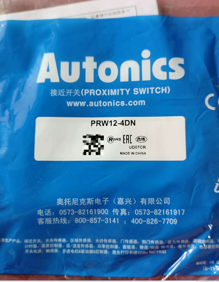

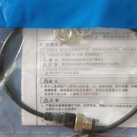
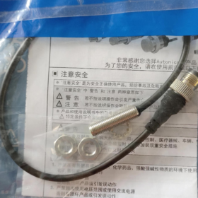
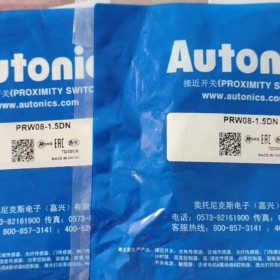
PRW12-4DN: M12 connector-type inductive proximity sensor, 3-wire DC, NPN normally-open, non-shielded flush-mount prohibited, sensing distance 4 mm
PRW series features M12 thread plus M12 circular connector interface (no fixed cable; requires mating connector cable). The standard PR12-4DN is cable-outlet type. They share identical sensing parameters and differ only in connection method.
Explication du code modèle
| Code | Description |
| PRW | Connector‑type inductive proximity sensor |
| 12 | M12 thread outer diameter |
| 4 | Rated sensing distance: 4 mm |
| D | DC power supply 12‑24 V |
| N | Sortie NPN |
| Pas de suffixe | Normalement ouvert (NON); 2=Normally‑Closed (Caroline du Nord); P=sortie PNP |
Principales spécifications électriques
Tension de fonctionnement: DC 10-30 V (rated 12-24 VDC)
Sortir: 3-wire NPN Normally-Open (NON)
Distance de détection: 4 mm ±10 %, non blindé (protruding-mount only; do not embed in metal)
Standard target: 12×12×1 mm iron plate
Response frequency: 500 Hz
Max load current: 200 mA
Consumption current: ≤10 mA
Protection: Reverse-polarity, surtension, short-circuit output protection
Classe de protection: IP67
Température de fonctionnement: -25 ℃ ~ +70 ℃
Logement: Nickel-plated brass; sensing face: PBT plastic
Interface: M12 4-pin male connector (sensor body is male; M12 female cable required)
Brochage M12-4 broches (PRW12-4DN)
| Numéro de broche. | Couleur du câble | Fonction |
| 1 | Brun | DC24V+ Power positive |
| 2 | Noir | Sortie NPN |
| 3 | Bleu | 0 V Power negative |
| 4 | ‑ | Inutilisé |
⚠️ M12 4-pin female-ended cable must be used (common lengths: 300 mm / 2 m / 5 m). No built-in cable on sensor body. Do not directly interchange with cable-outlet PR12-4DN due to different connector form.
Comparaison des séries
PRW12-4DN: NPN Normally-Open (ce modèle)
PRW12-4DN2: NPN Normally-Closed
PRW12-4DP: PNP Normally-Open
PRW12-4DP2: PNP Normally-Closed
Sélection alternative
- Original identical replacement: PRW12-4DN
- Cable-outlet variant: PR12-4DN (mêmes paramètres, fixed cable without connector)
- Alternatives compatibles nationales: M12 connector-type, 4 mm non-shielded, NPN-NO, DC24 V, par exemple. E2E-X4D1-M1G, HS-M12-4DN-W(M12 connector version)
Notes d'installation
- Non-shielded type: Do not embed sensing head into metal bore. Maintain sufficient clearance from surrounding metal.
- Montage côte à côte: sensor-to-sensor spacing ≥12 mm to prevent mutual interference.
- Optimal target material is iron; sensing range decreases for stainless steel, aluminium et cuivre. No response for non-metals.
- Commisioning: Red LED lights up when metal approaches sensing face, indicating output activation.
PRW12-4DN Supplementary Documentation (Wiring|Second-hand Inspection|Customs HS Code)
M12-4-pin male sensor; M12-4-pin female-ended cable is mandatory for operation.
- Définition des broches & Wiring Examples
| Numéro de broche. | Couleur du câble | Fonction |
| 1 | Brun | DC24V+ |
| 2 | Noir | NPN Output OUT |
| 3 | Bleu | 0 V GND |
| 4 | ‑ | Inutilisé |
① Connect to PLC (sink-input, typical for Japanese-brand PLCs)
- Brown → DC24V+
- Blue → DC24V(0 V)
- Black → PLC input terminal (I0.0)
- PLC input common COM/M connects to +24 V (critical for NPN sink-input)
Opération: Red LED illuminates upon metal approaching; output pulls down to 0 V; PLC input turns ON.
② Drive intermediate relay (NPN driving relay coil)
Brun: 24V+; Bleu: 0 V
Relay coil one terminal to 24V+, other terminal to sensor black output wire
⚠️ Connect free-wheeling diode in parallel across inductive coil for surge absorption. Max load current 200 mA must not be exceeded.
③ Common Wiring Mistakes
- Feed power to unused pin 4 → no output or permanent damage.
- PLC COM connected to 0 V → NPN sensor yields no signal.
- Use cable for direct-cable PR12-4DN: connector mismatch.
- Second-hand Unit Inspection Checklist for PRW12-4DN
Inspection visuelle
- M12 thread and M12 male pins: pas de flexion, corrosion or missing pins; connector sealing ring intact (IP67 performance depends on seal).
- Sensing face PBT plastic: no crack or chipping; housing nickel-plating without large-area peeling.
- LED indicator window undamaged.
Power-on Test (requis: DC12-24 V power supply, standard iron target)
- Câblage: Brown = 24V+, Blue = 0 V; connect black output to DC-voltage multimeter.
- No metal target: black output high-impedance, voltage near 24 V, LED OFF.
- Bring 12×12 mm iron plate within ≤4 mm: Red LED must turn ON, output voltage drops ≤1.5 V. Remove target: LED OFF, voltage recovers.
- Repeat test ≥10 times to rule out intermittent failure.
- Brief reverse-polarity test: sensor shall not be destroyed (built-in reverse-polarity protection).
Diagnostic des pannes
LED permanently ON after power-on: internal output transistor breakdown.
LED never lights: power-circuit failure.
Random flickering when target approaches: sensing-face wear or internal circuit aging.
Sensing distance obviously less than rated 4 mm: performance degradation; do not deploy on machine.
Application Risk Reminder
For second-hand non-shielded sensors, maintain metal clearance during installation. Sensing range shrinks for stainless-steel/aluminum targets; do not apply 4 mm setting directly.
- Customs HS-Code Reference
For reference only; subject to customs broker and on-site customs confirmation.
Commodity: Inductive proximity sensor PRW12-4DN, DC10-30 V, sortie de commutation
Code SH: 8536500000 Other electrical switching apparatus for voltage ≤1000 V
Éléments de déclaration: Marque: Autonique; Modèle: PRW12-4DN; Application: industrial position detection; Tension: DC10-30 V; Principe: inductive sensing; Sortir: NPN switching signal.
- Matching Cable Selection
Exigence: M12 4-pin female straight-head cable
Common lengths: 2 m, 5 m. Wire assignment: Pin1-Brown, Pin2-Black, Pin3-Blue, Pin4-unused.
Do not use M12-5-pin cable; leave extra pin unconnected.
Operating Principle of Autonics PRW12-4DN
PRW12-4DN is a 3-wire DC inductive proximity sensor based on eddy-current effect. It detects metal targets in non-contact mode with no mechanical contacts, delivering NPN Normally-Open (sink-type) switching signal.
- Four Core Internal Blocks
- LC high-frequency oscillator (sensing coil): Built-in coil at sensing face generates alternating high-frequency electromagnetic field when powered.
- Détecteur & threshold comparator: Monitors oscillation amplitude variation.
- NPN output transistor (sink output): Performs switching action.
- Auxiliary circuits: Red-LED indication, reverse-polarity protection, surge protection and short-circuit protection.
Powered by DC10-30 V, coil continuously emits high-frequency magnetic field; rated sensing distance 4 mm for iron targets.
- Principe de détection: Eddy-current Effect
- No metal approaching (normal state, Normalement ouvert)
Oscillator maintains stable high-frequency oscillation. Comparator judges “target absent”. Internal NPN transistor cuts off.
Black output wire electrically disconnected from 0 V (blue wire).
Output voltage close to 24 V (high level).
Red LED OFF.
- Metal target enters 4 mm sensing range
Alternating magnetic field penetrates metal workpiece. Eddy currents are induced inside metal. Eddy-current opposing magnetic field absorbs oscillator energy and attenuates oscillation amplitude.
Comparator detects amplitude drop reaching threshold and confirms “target present”.
NPN transistor turns ON, pulling black output wire down to 0 V potential.
Output voltage drops to approx. 0 V.
Red LED illuminates, signal output active.
- Metal target moves away
Eddy currents vanish; oscillator restores oscillation; NPN transistor cuts off; LED goes OFF, returning to idle condition.
⚠️ Eddy-current only occurs for conductive metals. Iron yields best performance. Sensing distance drops significantly for stainless-steel, aluminium et cuivre. No response for plastic, wood or glass.
- NPN-NO (Normalement ouvert) Sink-type Output Logic
PRW12-4DN output transistor sits between output wire and negative 0 V, not positive supply.
Target absent: transistor OFF. Open-circuit between black output and 0 V. Charger (PLC input / relais) must be externally powered by positive supply.
Target detected: transistor ON. Output wire pulled to 0 V. Current flows from load into sensor output pin and returns to power-supply negative.
Wiring key: PLC input COM terminal must connect to +24 V to recognize low-level valid signal.
- Non-shielded (protruding-mount) Caractéristiques
As non-shielded sensor, magnetic field leaks laterally from housing.
Must not embed into metal bore; surrounding metal consumes magnetic field, causing reduced sensing distance or false triggering.
Install protruding from metal surface. Installation côte à côte: sensor spacing ≥12 mm to avoid magnetic-field crosstalk.
- Protection-circuit Operation
Built-in protections: reverse-polarity, surtension, output short-circuit.
Brief reverse power connection will not destroy sensor.
Output short-circuit triggers internal current-limiting protection.
Pour charges inductives (relay coils), external free-wheeling diode is still recommended to suppress interference.
- Response Performance
Max response frequency 500 Hz: maximum 500 detections per second, suitable for high-speed counting and position confirmation. Signal loss occurs when operating frequency exceeds specification.
Résumé en langage simple
When powered on, the sensor emits invisible high-frequency magnetic field from its front face. Approaching metal induces eddy-currents that drain oscillation energy. Internal circuit identifies magnetic-field change and switches NPN transistor to connect output wire to 0 V, turning on red LED. After metal leaves, magnetic-field recovers; transistor opens and signal disappears.





NH42-63-318x560.png "Commutateurs de transfert automatiques de type PC CHINT (ATS)NH42-63/4SZ")



