 Contacteur,disjoncteur,capteur,Encodeur,API,Convertisseur


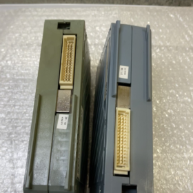
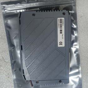
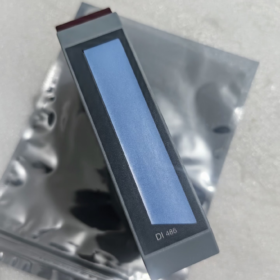
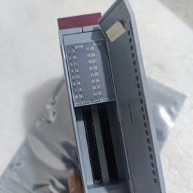
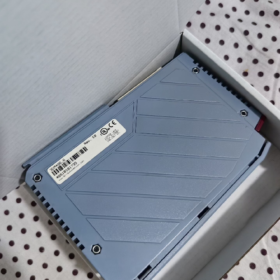
Informations de base
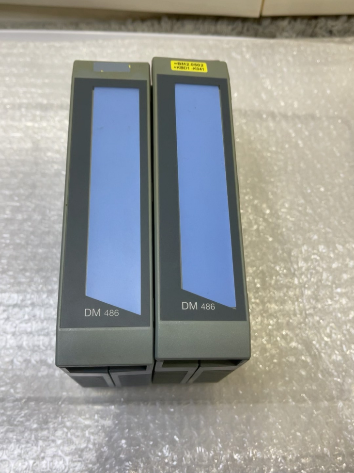
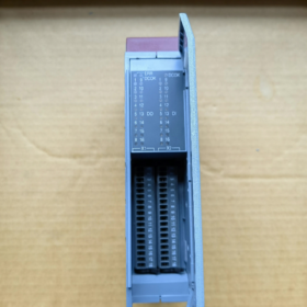
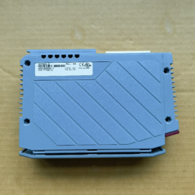
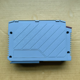
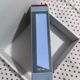
Modèle:3DM486.6
Marque: B&Automatisation R
Famille de produits: Système 2005 (Système de fond de panier PCC hérité)
Type de module: Numérique Module d'E/S mixtes
⚠️ Statut: Fabricant abandonné (Obsolète). Uniquement des pièces détachées de stock et d'occasion disponibles. Il est recommandé aux nouveaux projets de migrer vers la série X20.
- Spécifications du canal principal
| Article | Paramètre |
| Entrée numérique (DEPUIS) | 16 chaînes, 24 VCC, Compatible évier/source (NPN/PNP universel) |
| Temps de filtre d'entrée | 1 MS |
| Sortie numérique (FAIRE) | 16 chaînes, Sortie d'approvisionnement en transistors, 24 VCC |
| Courant de sortie par canal | 0.5 UN / indiquer |
| Courant de sortie total maximum du module | 8 UN |
| Isolation électrique | Isolation galvanique entre la banque d'entrée et la banque de sortie; pas d'isolation entre les canaux individuels |
| Diagnostic | Court-circuit de sortie / détection de surintensité, indication d'état LED par canal |
- Électrique & Spécifications environnementales
- Consommation d'énergie
Fond de panier 5 V: 1.2 W
Champ 24 V alimentation: 2.2 W
- Fonctions de protection
Arrêt thermique en cas de court-circuit en sortie, protection de charge inductive, protection contre l'inversion de polarité de l'alimentation externe
- Conditions environnementales
Température de fonctionnement: 0 ~ +60 °C
Stockage & Température de transport: -25 ~ +70 °C
Humidité relative: 5%~95 %, sans condensation
Classe de protection: IP20 (pour montage en armoire uniquement)
- Spécifications mécaniques
Système 2005 module simple largeur
Poids: environ. 0.32 kilos
- Terminaux obligatoires (Non inclus avec le module, commander séparément)
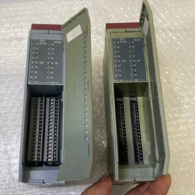
Le module est équipé de prises; les borniers doivent être commandés séparément. 2 pièces de bornes à 18 broches requises
7TB718.9: Bornier à vis, 1.5 mm²
7TB718.91: Bornier à ressort à pince à cage, 1.5 mm²
Connecteur X1: DO1 ~ DO16; Connecteur X2: DI1 ~ DI16
- Compatibilité logicielle
Version minimale d'Automation Studio prise en charge: V2.6
Package de mise à niveau matérielle correspondant requis: V1.0.1.0
- Options de remplacement (Informations clés)
1) Compatible drop-in au sein de la même plateforme (Conserver le fond de panier System2005 & Processeur)
Pas de modèle amélioré directement broche à broche. Référence similaire dans la série:
3DM476.6: 16DEPUIS + 16FAIRE, prend en charge les entrées DC/AC24 V (différentes caractéristiques électriques pour la sélection)
2) Migration de plateforme (Nouveaux projets / rénovation complète de l'armoire, Système2005 → X20)
Combinaison fonctionnellement équivalente:
X20DI9371 (16DEPUIS) + X20DO9322 (16FAIRE)
Avantages: Disponibilité stable à long terme, stock suffisant, fonctions de diagnostic améliorées.
- Applications typiques
Machines d'emballage, équipement textile, presses à imprimer, modernisation des anciennes lignes de production; utilisé pour l'acquisition de signaux provenant de commutateurs de proximité et de boutons-poussoirs, et piloter de petites charges telles que des électrovannes et des voyants lumineux.
⚠️ Sélection & Précautions d'entretien
- La sortie est de type Sourcing (PNP). Connectez la borne négative de la charge à 0 V; ne peut pas être directement câblé pour un entraînement coulant.
- Ne dépassez pas 0.5 Un courant continu par canal; Le courant de sortie total du module ne doit pas dépasser 8 UN.
- Les diodes de roue libre doivent être câblées en parallèle pour les charges inductives (électrovannes).
- Les modules de fond de panier System2005 ne peuvent pas être branchés directement sur les bases X20; les protocoles de bus de fond de panier sont incompatibles.
- Lors de l'achat de pièces de rechange discontinuées, distinguer remis à neuf / utilisé / tout nouveau stock excédentaire et confirmer les conditions de garantie.
Si nécessaire, je peux fournir:
1) Tableau complet d'affectation des broches des bornes
2) Schéma de câblage standard DI/DO
3) Points clés de configuration pour la configuration matérielle d'Automation Studio
B&Manuel d'installation du matériel R 3DM486.6 (Version de terrain)
Plateforme de produits: B&Système R 2005 PCC
Type de module: 16DEPUIS / 16DO Module d'E/S mixtes numériques
Statut: Fabricant abandonné, pour utilisation comme pièce de rechange uniquement
Portée: Assemblage d'armoires, câblage, mise sous tension, dépannage
Table des matières
- Consignes de sécurité
- Produit & Liste des accessoires
- Installation mécanique (Procédure de montage du fond de panier)
- Affectation complète des broches des bornes
- Spécifications du câblage électrique (Schéma DI/DO)
- Environnemental & Dimensions de montage
- Inspection à la mise sous tension & Définition des indicateurs LED
- Directives de configuration d'Automation Studio
- Restrictions opérationnelles & Défauts courants
- Mise à niveau & Conseils de remplacement
- Consignes de sécurité obligatoires
- Insertion des modules / le retrait doit être effectué avec l'alimentation débranchée! Le branchement à chaud des modules de fond de panier System2005 est strictement interdit; cela peut endommager de manière permanente les interfaces du bus du fond de panier.
- Mettre en œuvre une protection ESD avant la manipulation; porter un bracelet antistatique. Les circuits imprimés sont sensibles aux décharges électrostatiques.
- Des fusibles doivent être installés pour les 24 Alimentation VCC; l'inversion de polarité de l'alimentation est interdite.
- Les diodes de roue libre doivent être montées en parallèle aux charges inductives (électrovannes, contacteurs) piloté par les canaux de sortie.
- Indice de protection des modules IP20, installation à l'intérieur de l'armoire de commande uniquement. Ne pas exposer directement à la poussière ou à l'humidité.
- Une isolation galvanique existe entre la banque DI et la banque DO; pas d'isolation canal à canal. Séparez les câbles d'E/S de bas niveau des câbles d'alimentation pendant le câblage.
- Module & Accessoires obligatoires
Module principal
Modèle: 3DM486.6
Canaux: 16×DI (24 Puits/Source VDC) + 16×FAIRE (24 Sortie transistor d'approvisionnement VDC, 0.5 Un par canal)
Bornes à commander séparément (Non fourni avec le module)
7TB718.9: 18-bornier à vis à broches, section maximale du conducteur 1.5 mm²
7TB718.91: 18-broche Cage Clamp ressort bornier, section maximale du conducteur 1.5 mm²
Quantité requise: 2 borniers (X1 pour FAIRE, X2 pour DI)
- Étapes d'installation mécanique pour le fond de panier System2005
- Confirmer la mise hors tension complète de l'ensemble du rack PCC; isoler le module d'alimentation du secteur.
- Alignez les fentes de guidage inférieures du module avec les guides du fond de panier sur rail DIN et glissez-les horizontalement dans la fente..
- Appuyez sur les loquets latéraux vers l'intérieur jusqu'à ce qu'un clic audible confirme que le module est verrouillé sur le fond de panier..
- Vérifiez que le connecteur de bus arrière plaqué or est bien en place contre le connecteur du fond de panier, sans inclinaison ni espace..
⚠️ Ne soulevez pas le module avec des tournevis. Pour supprimer, relâchez les loquets latéraux et retirez le module parallèlement au fond de panier..
- Insérez verticalement les fiches des bornes 7TB718 dans les prises inférieures X1 et X2 du module jusqu'à ce qu'elles soient complètement engagées..
Exigences de dégagement de montage
Maintenir un minimum 25 mm espace de ventilation au-dessus et en dessous de chaque module;
Température ambiante de fonctionnement 0 ℃ ~ +60 ℃. Mettre en œuvre une réduction de la température de l'armoire si elle fonctionne continuellement au-dessus 55 ℃.
- Affectation complète des broches des bornes
X1 = Borne de sortie (DO1 ~ DO16)
X2 = Borne d'entrée (DI1 ~ DI16)
X1 (DO Sortie, 18 Épingle)
| Épingle | Signal | Description |
| 1 | FAIRE1 | Sortie numérique 1 |
| 2 | DO2 | Sortie numérique 2 |
| 3 | DO3 | Sortie numérique 3 |
| 4 | FAIRE4 | Sortie numérique 4 |
| 5 | FAIRE5 | Sortie numérique 5 |
| 6 | FAIRE6 | Sortie numérique 6 |
| 7 | FAIRE7 | Sortie numérique 7 |
| 8 | FAIRE8 | Sortie numérique 8 |
| 9 | FAIRE9 | Sortie numérique 9 |
| 10 | FAIRE10 | Sortie numérique 10 |
| 11 | FAIRE11 | Sortie numérique 11 |
| 12 | DO12 | Sortie numérique 12 |
| 13 | FAIRE13 | Sortie numérique 13 |
| 14 | FAIRE14 | Sortie numérique 14 |
| 15 | FAIRE15 | Sortie numérique 15 |
| 16 | DO16 | Sortie numérique 16 |
| 17 | +24V_OUT | Alimentation positive commune pour les sorties (routé en interne sur le module) |
| 18 | 0V_GND | Terrain d’entente pour les résultats |
✅ Type de sortie: Approvisionnement / Sortie PNP
Lorsque DO est activé, +24 V est présent sur la broche DO. Connectez une borne de charge à DO, l'autre terminal à 0 V.
X2 (Entrée DI, 18 Épingle)
| Épingle | Signal | Description |
| 1 | DI1 | Entrée numérique 1 |
| 2 | DI2 | Entrée numérique 2 |
| 3 | DI3 | Entrée numérique 3 |
| 4 | DI4 | Entrée numérique 4 |
| 5 | DI5 | Entrée numérique 5 |
| 6 | DI6 | Entrée numérique 6 |
| 7 | DI7 | Entrée numérique 7 |
| 8 | DI8 | Entrée numérique 8 |
| 9 | DI9 | Entrée numérique 9 |
| 10 | DI10 | Entrée numérique 10 |
| 11 | DI11 | Entrée numérique 11 |
| 12 | DI12 | Entrée numérique 12 |
| 13 | DI13 | Entrée numérique 13 |
| 14 | DI14 | Entrée numérique 14 |
| 15 | DI15 | Entrée numérique 15 |
| 16 | DI16 | Entrée numérique 16 |
| 17 | COM+24V | Positif commun pour les entrées (utilisé pour NPN / Capteurs de descente) |
| 18 | COM_0V | Terrain d’entente pour les intrants (utilisé pour PNP / Approvisionnement en capteurs) |
Deux configurations de câblage DI
- Capteur PNP (Type d'approvisionnement)
Capteur positif → canal DI; Capteur négatif → 0 V; Connectez le module X2.18 au champ 0 V
- Capteur NPN (Type coulant)
Capteur positif connecté à 24 V; Sortie capteur → canal DI; Connectez le module X2.17 au champ +24 V
Filtre matériel d'entrée: Fixé à 1 MS, non réglable par logiciel.
- Caractéristiques électriques
Fond de panier 5 consommation électrique V: 1.2 W
Champ 24 consommation électrique V: 2.2 W
Sortie continue maximale par canal: 0.5 Un DC24 V
Limite globale de courant de sortie du module: 8 UN; prolonged overload not permitted
Isolement: Galvanic isolation between DI bank and DO bank; pas d'isolation entre les canaux individuels
Protection: Thermal shutdown for output short-circuit, protection contre l'inversion de polarité
- Dimensions des modules (mm)
Largeur: 25 (System2005 single-width module)
Hauteur: 130
Profondeur: 86
Poids: environ. 320 g
- Définition des indicateurs LED
One LED assigned per channel on module front face:
DI LED ON: High level detected on corresponding input channel
DO LED ON: Output enabled in program and hardware output switched ON
Power status: Standby LEDs illuminated when backplane supply is normal; no LED response upon backplane communication failure.
- Automation Studio Hardware Configuration Guidelines
- Minimum supported AS version: V2.6 and above
- Hardware library selection: `3DM486.6` System 2005 DM module
- Address mapping: Follow rack slot sequence; slot numbering starts from CPU and extends backward
- Diagnostics support: Software readable faults for output short-circuit and overload
Important: Ne peut pas être installé directement sur le fond de panier X20; les protocoles de bus sont incompatibles!
- Matrice de dépannage des pannes
| Symptôme de panne | Cause fondamentale possible | Mesure corrective |
| Pas d'éclairage LED sur le module | Alimentation du fond de panier absente / Mauvais positionnement des modules / Fond de panier endommagé | Réinstaller le module après une mise hors tension complète; Inspecter les modules d'alimentation 3PS465/3PS476 |
| DO LED ON, charge externe inactive | Externe manquant 24 V alimentation, rupture de câble, échec du chargement | Mesurer la tension à X1.17/18; Inspecter le câblage de charge |
| Alarmes récurrentes de court-circuit sur les sorties | Charge en court-circuit, courant par canal dépassant 0.5 UN, diode de roue libre manquante pour les charges inductives | Installer des diodes de roue libre; répartir le courant de charge; Inspecter les câbles pour déceler tout dommage à l'isolation |
| Signaux DI fluctuants | Interférence électromagnétique, filtrage insuffisant, câbles trop longs | Acheminer les câbles DI séparément; ajouter des circuits d'amortissement RC; vérifier l'ondulation de la tension d'alimentation |
| Panne de canal individuel | Canal grillé à cause d'une surintensité; non réparable | Remplacer le module |
- Rénovation & Conseils de remplacement
Compatibilité avec la même plateforme (Aucune modification du processeur/fond de panier)
Modèle similaire: 3DM476.6 (Prend en charge les entrées AC24 V; l'affectation des broches diffère, modification du câblage requise)
Système de mise à niveau de plate-forme2005 → X20 (Recommandé pour les nouveaux projets)
Combinaison fonctionnellement équivalente:
X20DI9371 (16DEPUIS) + X20DO9322 (16FAIRE)
Avantages: Disponibilité de production à long terme, approvisionnement stable en pièces de rechange, capacité de diagnostic améliorée.
- Spécifications techniques de câblage
- Séparez les câbles de signaux E/S des câbles d'alimentation, distance de séparation minimale ≥30 cm; utiliser des câbles blindés si la séparation ne peut pas être obtenue.
- Installez des fusibles indépendants pour tous 24 Circuits VCC (3~5 A note recommandée).
- Mettre en œuvre une mise à la terre en un seul point à l'intérieur de l'armoire de commande; connecter de manière fiable la terre du signal et la terre de protection.
- Section de câble recommandée: 0.75~1,0 mm².





NH42-63-318x560.png "Commutateurs de transfert automatiques de type PC CHINT (ATS)NH42-63/4SZ")



