 Contacteur,disjoncteur,capteur,Encodeur,API,Convertisseur

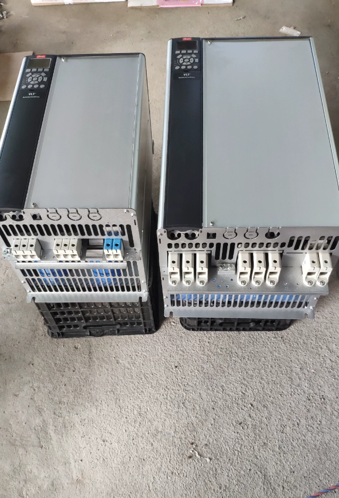

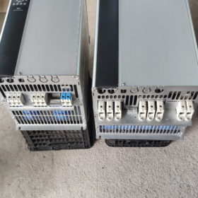
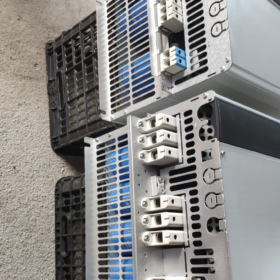
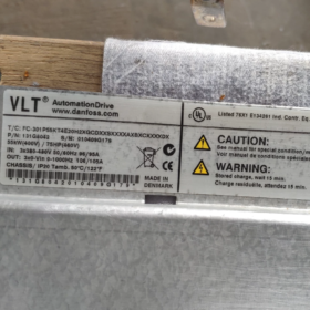
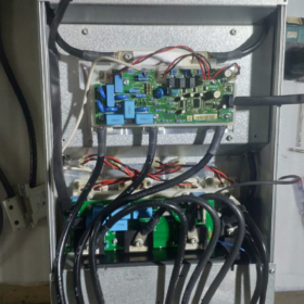
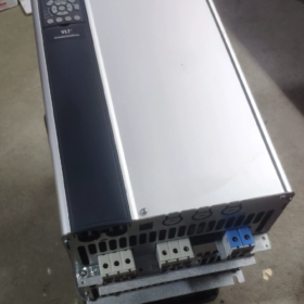
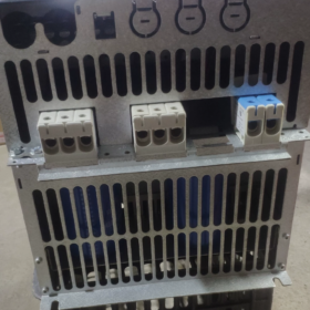
VLT AutomationDrive FC-302 High-Performance General-Purpose Convertisseur de fréquence
Numéro de commande: 131F7151
Model Segment-by-Segment Decoding
FC-302 P55K T5 E20 H2 B G XXXX SXXXX AXBXCXXXXDX
| Champ | Signification | Description |
| FC‑302 | Série de produits | VLT AutomationDrive FC‑302, with motion control, Safe‑Stop, supports servo‑type applications |
| P55K | Puissance nominale | 55 kW / 75 HP |
| T5 | Power Supply Specification | 3‑phase 380‑500 V AC |
| E20 | Protection contre la pénétration | IP20 open‑frame, installation sur armoire |
| H2 | RFI Filter | Class C3 industrial EMC filter (2nd environment, factory‑floor use) |
| B | Hachoir de frein | Hacheur de freinage intégré, brake resistor connectable |
| G | Panneau de commande | LCP102 graphical Chinese panel (afficher & clavier) |
| XXXX | PCB Coating / Power Option | X = Standard uncoated PCB, no extra power‑supply options |
| SXXXX | Software Revision | Latest factory‑standard firmware version |
| HACHE | Option Slot A | No A‑slot communication card (slot A empty; Profinet, EtherNet‑IP etc. can be retrofitted) |
| BX | Option Slot B | No B‑slot expansion card |
| CX | Option Slot C | No C‑slot MCO motion‑control card |
| DX | Option Slot D | No D‑slot option card |
Spécifications électriques de base
Puissance nominale: 55 kW
Saisir: 3-phase 380-500 V AC
Continuous output current: 106 UN
Surcharge: 160 % for 1 min (high-overload mode)
Chassis frame size: C4
On-board components: DC link reactor, brake chopper, Class C3 RFI filter
Standard protocol: Modbus-RTU; no additional communication cards fitted
Fonction de sécurité: Safe-Stop hardware terminal
Température ambiante: Full-rating at 40 °C; derate above up to max. 50 °C
Key Configuration Summary
✅ 55 kW, 380-500 V, IP20 open-frame
✅ Built-in brake chopper, compatible with brake resistor
✅ Equipped with LCP-102 graphical operator panel
✅ Class C3 industrial EMC filter, integrated DC-link reactor
❌ No Profinet / EtherNet-IP or other fieldbus cards; can be retrofitted via A/B slots
❌ No MCO motion-control card
Applications typiques
Ventilateurs, pompes, extrudeuses, convoyeurs, mélangeurs, broches de machines-outils. Supports closed-loop vector, open-loop and servo modes; suitable for applications with regenerative braking energy.
Spare-part & Replacement Hints
- If brake chopper is not required: change B to X; order number will differ.
- For Profinet: fit option AL (MCA120); for EtherNet-IP: fit option AN (MCA121).
- Same power rating without panel: replace G with X, model becomes FC-302P55KT5E20H2BXXXXSXXXXAXBXCXXXXDX
FC-302P55KT5E20H2BGXXXXSXXXXAXBXCXXXXDX
55 kW / 380-500 V IP20, built-in brake chopper, Class C3 EMC filter, LCP102 graphical Chinese panel; no communication card, no MCO motion-control card.
- Essential Wiring Notes (power OFF; allow DC-bus minimum 20 min discharge time)
Main-Power Circuit
| Terminal | Fonction | Remarques |
| L1/L2/L3 | 3‑phase 380‑500 V input | Do NOT swap with U/V/W motor terminals |
| U/V/W | Sortie moteur | Connect to 3‑phase motor; shielded cable recommended |
| BR+ / BR‑ | Résistance de freinage | For built‑in brake chopper; connect brake resistor here, DO NOT connect to DC‑bus terminals |
| +DC /‑DC | DC‑link bus | Used for common‑DC‑bus multi‑drive systems; leave unconnected for standard operation |
| PE | Terre de protection | Reliable earthing mandatory |
Cable sizing suggestion for 55 kW: power-supply cable ≥16 mm²; motor cable ≥16 mm²; brake-resistor cable ≥10 mm².
Control-circuit mandatory connections (fault or drive-inhibited if ignored)
- STO Safe-Torque-Off: short terminal 12 à 37. Without short-circuit, inverter output is inhibited. For external safety circuits, wire safety contacts in series.
- Coast-to-stop terminal 27 is factory-active: if coast-to-stop is not needed: set parameter 5-12 = 0 (no function). To retain coast-to-stop: court 12-27.
- Terminaux 12/13: internal +24 V output (max. 200 mA); terminal 20 = digital-input common ground.
- Entrées analogiques: 53 (0-10 tension V); 54 (4-20 mA). Hardware dip-switches select voltage / mode actuel.
- Terminaux 68/69: RS485 Modbus-RTU; 68 = A, 69 = B.
Example terminal-based start-stop logic
18 (DEPUIS): Commencer (parameter 5-10 = Start)
19 (DEPUIS): Inverse (parameter 5-11 = Reverse)
54: 4-20 mA frequency reference
Relais 01-02-03: configurable for Run / Fault signalling.
Practical advice: power-up without motor first and check I/O status. For commissioning, decouple motor coupling and test at low speed.
- Factory-reset procedures
Method 1: Recommended Initialisation (retains run-hours and communication settings)
- Main Menu → 14-Special Functions → 14-22 Mode de fonctionnement
- Sélectionner 2 Initialisation → press OK
- Disconnect main supply; wait until panel fully dark; re-apply power
- A80 “Drive initialised” informational message appears (not a fault); press Reset.
Méthode 2: Full Hard Initialisation (all parameters cleared)
- Mise hors tension; wait for panel to extinguish.
- Hold Status + Main Menu + OK keys together, then switch-on main supply.
- Keep holding for 5 s then release. Full factory reset completes on power-on.
Parameter backup tip: 0-50 LCP Copy → select 1 Copy all parameters to LCP. The panel can store parameters for download to identical units. Do NOT copy parameters across different power ratings.
- Key Commissioning Parameters (unit fitted with built-in brake chopper)
| Paramètre | Description | Suggested Setting |
| 1‑01 | Motor Control Principle | VVCplus / Flux Vector. Asynchronous motor: VVCplus; high low‑speed torque: select Flux Vector |
| 1‑20~1‑26 | Motor Nameplate Data | Enter nameplate power, tension, actuel, fréquence, speed exactly |
| 1‑29 | AMA Motor Auto‑Tune | Static AMA; perform with mechanical load decoupled |
| 2‑10 | Fonction de freinage | Enable built‑in brake chopper → 1 Enable |
| 2‑11 | Brake‑resistor Ohmic Value | Input actual resistor value for thermal protection |
| 2‑12 | Brake‑resistor Power Rating | Input resistor power rating to activate resistor thermal‑model protection |
| 3‑41/3‑42 | Ramp up‑/down‑time | Lengthen deceleration for high‑inertia loads to avoid AL‑16 over‑voltage |
| 5‑10/5‑11 | Digital‑Input Functions | Configure start‑stop, direction commands |
Brake-chopper warning: short-circuited or under-rated low-ohm resistors will destroy the brake chopper. Always populate 2-11 & 2-12 for thermal protection.
- Incoming-inspection checklist for second-hand FC-302-55 kW (C4 frame)
Inspection visuelle
- PCB: check for water ingress, corrosion or burn marks. Examine cooling air-path and fan for heavy dust. Manually spin fan for free rotation, pas de collage.
- Bornes de puissance: check for arcing / burn damage. Verify nameplate model string: FC-302P55KT5E20H2B G……, order No. 131F7151.
- Test all keys on LCP102 graphical panel.
Power-off static multimeter tests (full DC-bus discharge mandatory)
- Rectifier stage: measure forward / reverse diode drop L1/L2/L3 against +DC /-DC.
- IGBT stage: measure U/V-W versus +DC, -CC. Three-phase readings must be well-matched; large deviation indicates module failure.
- Brake circuit: test BR+ / BRchopper transistor for short-circuit breakdown.
- Confirm no control-terminal-to-earth short-circuits.
No-load power-on test (motor disconnected)
- Mise sous tension, verify no active faults. Read run-hours 15-00; inspect fault-history log 15-30.
- Perform factory reset then AMA auto-tune. Run 0-50 Hz no-load; check three-phase output-voltage balance. Unbalance points to IGBT / drive-board damage.
- Brake-chopper functional test: set short deceleration time to induce regeneration; observe DC-bus voltage rise and brake activation.
- STO test: ouvrir 12-37 link → STO fault appears; re-short to clear.
- Full point-by-point test for all digital inputs and relay outputs.
Motor-coupled test
Disconnect mechanical load. Run motor, verify balanced 3-phase current, no vibration or abnormal noise. High-overload 160 % / 1 min test: exercise with caution.
Common failure items: fan wear, current-sensor drift, brake-chopper damage, STO safety-circuit faults, aged electrolytic capacitors. Typical alarms: AL13 Over-current, AL16 Over-voltage, AL29 Heatsink Over-temp, AL-8 STO fault.
- Domestic Chinese-manufactured alternative selection (55 kW high-performance vector, 380-500 V)
FC-302 features: flux-vector control, asynchronous & PMSM support, built-in DC-link reactor, built-in brake chopper, expandable fieldbus cards, STO Safe-Torque-Off. Verify feature-match before substitution.
| Marque & Modèle | Key Matching Features | Remarques |
| Innovation MD380‑T55‑G | Open‑ / closed‑loop vector; STO‑capable; Profinet / EtherCAT expandable; brake‑unit optional | General‑purpose industrial constant‑torque. Confirm brake‑chopper availability for your project. |
| INVT CHV190‑055G‑4 | Vecteur haute performance; asynchronous / PMSM support; expandable fieldbus; STO | For extruders, convoyeurs, mélangeurs; brake unit built‑in or external option |
| Delta CH2000‑55 kW | Flux‑vector control; STO safety; expandable communication cards | Heavy‑duty applications, good substitution compatibility |
Substitution caveats:
- Original FC-302 has integrated DC-link reactor. Many domestic alternatives omit this; add external DC-reactor for sites with high-harmonic-grid conditions.
- Original unit includes built-in B-option brake chopper. Confirm alternative unit has on-board brake chopper or plan for external brake unit.
- STO Safe-Torque-Off may be an option card for some domestic drives; do not overlook for safety-related machinery.
- Communications: base unit has no fieldbus card (MCA120 Profinet retrofittable). Confirm bus-interface requirements for replacement drive.
- Quick fault-troubleshooting guide
- Drive will not run; alarm AL-8: inspect STO loop (12-37 court-circuit / safety-contact continuity).
- Coast-to-stop-related alarm: either short 12-27 or set parameter 5-12 to no-function.
- Deceleration over-voltage AL16: ① extend deceleration ramp time; ② confirm brake chopper enabled; ③ validate brake-resistor value & puissance nominale.
- AL29 Heatsink Over-temperature: clean dust build-up, inspect fan, reduce carrier-frequency, limit sustained ambient temperature ≤40 °C.
Danfoss FC-302P55KT5E20H2BGXXXXSXXXXAXBXCXXXXDX Full Detailed Specifications
Série: VLT® AutomationDrive FC-302; Numéro de commande: 131F7152 (B = built-in brake chopper, G = LCP102 graphical Chinese panel)
Taille du cadre: C4; IP20 cabinet-mount open-frame; 3-phase 380-500 V; 55 kW / 75 HP; integrated DC-link reactor, Class C3(A2) RFI filter, built-in brake chopper; no A/B/C/D option-cards; standard uncoated PCB.
- Main Supply Input Ratings
| Article | Spécification |
| Tension d'entrée | 3‑phase 380‑500 V AC, tolerance ‑10 % ~ +10 % |
| Fréquence d'entrée | 50/60 Hz ±5 % |
| Courant d'entrée nominal | 112 UN (@400 V nominal) |
| Integrated DC‑link Reactor | ✅ Norme. Mitigates mains harmonics; meets IEC 61000‑3‑12 |
| RFI / Filtre CEM | H2 = Class C3(A2), 2nd industrial environment. Factory‑floor application only; not for residential locations |
| Power‑Factor Performance | High fundamental power factor > 0.98 via DC‑link reactor |
| Supply‑Drop‑Out Handling | Voltage ride‑through function configurable |
- Sortie moteur: Pouvoir, Actuel & Surcharge (C4 frame, 55 kW)
| Article | Valeur |
| Continuous Power Rating | 55 kW / 75 HP |
| High‑Overload Continuous Output Current | 106 UN (380‑440 V); 105 UN (441‑500 V) |
| High‑Overload Intermittent Over‑current | 160 % × In = 169 A, 60 s duration, once per 10 min cycle |
| Normal‑Overload Continuous Current | 147 UN (380‑440 V) / 130 UN (441‑500 V) |
| Normal‑Overload Overload Ratio | 110 %, 60 s duration |
| Plage de tension de sortie | 0 up to input‑supply voltage |
| Output‑Frequency Range | 0‑1000 Hz |
| PWM Carrier‑Frequency | Factory default 4 kHz; adjustable 2‑16 kHz; derate power at higher carrier frequencies |
| Control Algorithms | VVCplus, open‑/closed‑loop flux vector, permanent‑magnet synchronous motor, servo mode |
| Motor Auto‑Tune AMA | Static AMA and rotating AMA supported |
Application guidance: High-overload for extruders, mélangeurs, palans. Normal-overload for fan-pump quadratic-torque loads.
- Brake-circuit Specifications (B-option built-in brake chopper)
| Article | Spécification |
| Hachoir de frein | ✅ On‑board integrated via BR+ / BR‑ terminals; external brake unit unnecessary |
| Peak Brake Power | 110 kW peak for this 55 kW frame |
| Minimum Permissible Brake‑resistor Resistance | 13 Ω minimum. Never use lower‑value resistors; chopper destruction risk |
| Brake‑resistor Thermal‑protection | Software thermal‑model via parameters 2‑11 resistor‑value; 2‑12 resistor‑power rating |
| DC‑bus Operating‑voltage | Typical 540‑675 V; brake‑chopper activation threshold 785 V for 400 V systems |
| Common‑DC‑bus Compatibility | +DC /‑DC terminals support multi‑drive common‑DC‑bus system architecture |
- Safety-related Functions
- STO Safe-Torque-Off (hard-wired terminals 12-37), PL d / SIL 2 rating. Hardware-level IGBT gating inhibition; cannot be overridden by software.
- Coast-to-stop via digital-input terminal 27.
- Motor thermal-protection: ETR electronic thermal relay; CTP / KTY84 temperature-sensor inputs.
- I/O Interface Specifications (Tableau de contrôle)
Entrées numériques DI (6 channels total)
Logic level 24 V, PNP / NPN compatible. Input impedance ~ 2 kΩ. On-board 24 V supply max. 200 mA.
Terminaux: 18, 19, 27, 29, 32, 33; common reference terminal 20.
Sorties numériques DO (2 open-collector channels)
24 V, maximum 40 mA sink-current.
Sorties relais (3 relais)
01-02-03: AC 250 V, 2 UN; 04-05-06; 07-08-09. Configurable for Run, Faute, Alarm signalling.
Analogue Inputs AI
AI53: 0-10 V voltage input.
AI54: hardware-dip-switch selectable 0-10 V / 4-20 mA. Impédance d'entrée: voltage-mode 10 kΩ; current-mode 200 Ω.
Analogue Output AO
AO42: 0-10 V, max. 1 mA. Can output frequency, motor-current, torque etc.
Communications Interfaces
Matériel standard: RS485 Modbus-RTU (terminals 68 A, 69 B).
Slots A/B/C/D empty as-delivered. Retrofit-capable options: MCA120 (Profinet), MCA121 (EtherNet-IP), MCA111 (AppareilNet), MCO305 motion-control card.
- Dimensions mécaniques, Poids & Évaluations environnementales (C4 frame IP20)
| Article | Valeur |
| Hauteur H | 1300 mm |
| Largeur W | 420 mm |
| Profondeur D | 386 mm |
| Poids net | 46.4 kilos |
| Gross Shipping Weight | 49.5 kilos |
| Méthode de refroidissement | Forced air‑cooling; replaceable fan module; rear‑channel air‑flow path |
| Montage | Cabinet‑mount IP20 only, not for direct exposed field installation. Side‑by‑side tight‑pack cabinet‑mount permitted. |
Conditions environnementales de fonctionnement
Operating ambient: -10 °C ~ +40 °C full power. Derate output > 40 °C; absolute maximum operating temperature 50 °C (déclassé).
Stockage & température de transport: -25 °C ~ +65 °C.
Altitude: full rating ≤ 1000 m above sea-level; derate 1 % output power per additional 100 m elevation.
Revêtement PCB: XXXX = standard uncoated PCB. Specify coated-PCB variant for corrosive-gas environments.
- Perte de puissance & Efficacité
Total power loss at nominal load: approx. 1020 W.
Efficacité: 98 % at rated operating point.
- Panneau de commande & Logiciel
LCP102 graphical multi-language Chinese-capable keypad-display (G-option). Parameter copy-backup feature; panel-extension-cable support for remote mounting.
Firmware identifier SXXXX = latest factory production firmware.
Commissioning software MCT-10: PC-connected upload / download parameters, fault-log recording.
- Hardware Protection & Alarm Events
Over-current, surtension, sous-tension, earth-fault, output short-circuit, heatsink over-temperature, surcharge du moteur, STO Safe-Stop, brake-resistor over-temperature, fan-fault, communication-fault.
- Full Model-code Re-check
FC-302 P55K T5 E20 H2 B G XXXX SXXXX A X B X C XXXX D X
FC-302: product family
P55K: 55 kW power
T5: 3-phase 380-500 V supply
E20: IP20 open-frame construction
H2: Class C3 RFI filter
B: Built-in brake chopper (key feature of this unit)
G: LCP-102 graphical operator panel
XXXX: uncoated standard PCB, no auxiliary-power options
SXXXX: factory-standard firmware
HACHE / BX / CX / DX: slots A/B/C/D empty, no fieldbus or motion-control cards fitted.
Remarque importante: Part-number 131F7151 corresponds to variant without brake-chopper and without operator-panel (B=X, G=X). The present full-feature unit uses order-number 131F7152 (B+G options).





NH42-63-318x560.png "Commutateurs de transfert automatiques de type PC CHINT (ATS)NH42-63/4SZ")



