 Contacteur,disjoncteur,capteur,Encodeur,API,Convertisseur

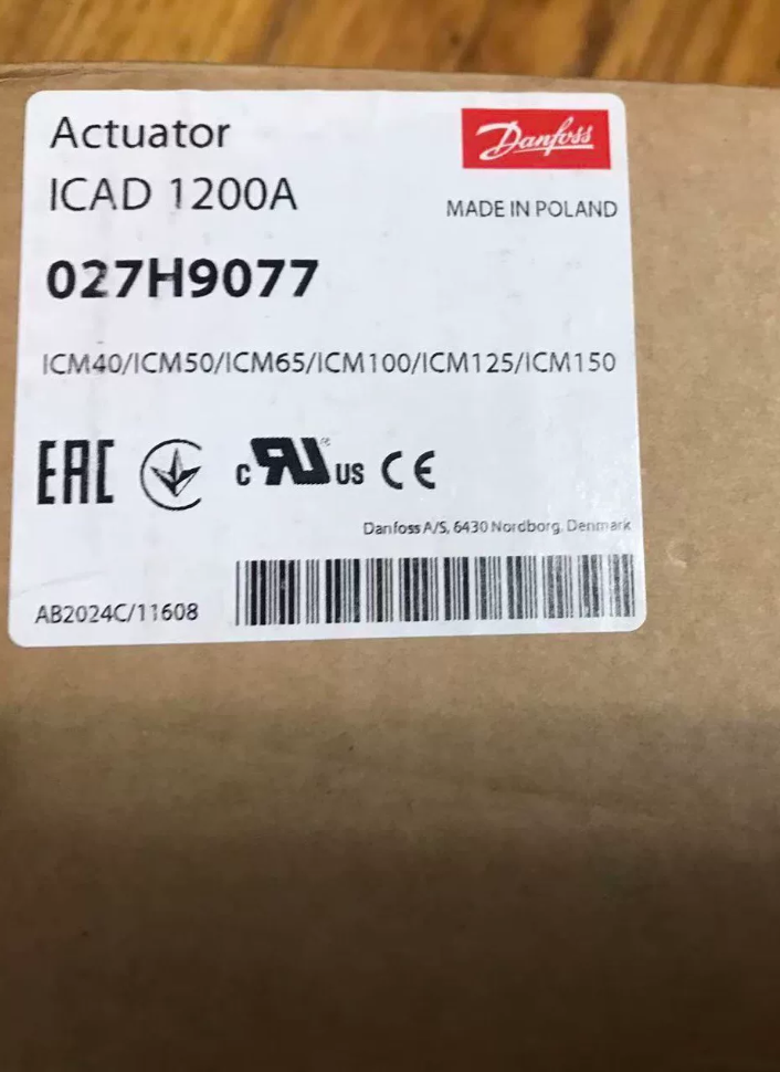
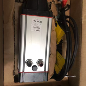
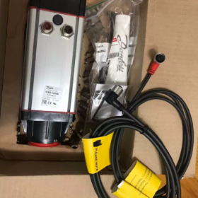
⚠️Remarque importante: Le numéro de pièce 027H9075 correspond à ICAD600A (PAS ICAD1200A).
Numéro de pièce ICAD1200A: 027H9077, courant nominal 2,0A.
027H9075: ICAD600A, 24 VCC, évalué à 1,2 A, compatible avec ICM20-32
027H9077: ICAD1200A, 24 VCC, évalué à 2,0 A, compatible avec ICM40-150
- Répartition du code modèle
| Numéro de pièce | Modèle | Alimentation | Courant nominal | Corps de vanne compatible |
| 027H9075 | ICAD600A | 24 VCC | 1.2 UN | ICM‑20/25/32 |
| 027H9077 | ICAD1200A | 24 VCC | 2.0 UN | ICM‑40…ICM‑150 |
ICAD = Actionneur à moteur pas à pas pour vannes motorisées ICM; VersionA: encodeur intégré + clavier MMI LCD local.
- Paramètres électriques de base (ICAD-1200A 027H9077, 24 V2.0A)
| Article | Spécification |
| Alimentation | 24 Alimentation isolée VDC; tolérance+10 %/‑15 % (21‑26,4 Vcc) |
| Consommation actuelle maximale | 2.0 UN |
| Alimentation de sécurité en option | 24 Onduleur VCC / batterie, 2.0 UN |
| Entrée analogique | 0/4-20 mA (200 Oh); 0/2-10 V (10 kΩ) |
| Sortie analogique | 0/4-20 mA, maximum. charge250Ω |
| Entrée numérique | Commande marche/arrêt par contact sec passif |
| Sortie numérique | 3Sorties à collecteur ouvert NPN à canal (vanne complètement ouverte, entièrement fermé, alarme); externe 5‑24 VCC requis |
| Protection contre la pénétration | IP67 |
| Température ambiante | -30 ℃ ~ + 50 ℃; condensation / conditions de givrage interdites |
| Poids | Env. 1,9 kg |
| Interfaces | 2 × Connecteurs circulaires M12: 4alimentation des broches, 8signal à broche |
- Principe de fonctionnement
L'ICAD utilise un moteur pas à pas à grande vitesse avec une transmission sans engrenage à couplage magnétique pour entraîner la vanne motorisée ICM.. Un codeur de position intégré fournit un retour de position de vanne en boucle fermée.
Fonctions prises en charge:
- Modulation continue via 4-20 mA / 2-10 V signal analogique.
- Contact sec numérique entièrement ouvert / commutation complètement fermée.
- Clavier LCD local pour la configuration des paramètres, indication de position et lecture du code défaut.
Conception à couplage magnétique: Pas de liaison mécanique rigide entre l'actionneur et le corps de la vanne; élimine le risque de fuite de réfrigérant.
- Affectation des broches: Connecteur de signal M12 à 8 broches
| Épingle | Couleur du fil | Fonction |
| 1 | Blanc | 24 V CC Positif |
| 2 | Brun | 24 V CC Négatif |
| 3 | Noir | Sortie d'alarme NPN‑ |
| 4 | Brun | Sortie entièrement ouverte NPN‑ |
| 5 | Rouge | Sortie entièrement fermée NPN‑ |
| 6 | Orange | Signal GND |
| 7 | Jaune | 4Entrée -20 mA (+) |
| 8 | Vert | 2Entrée -10 V / DANS Entrée numérique (+) |
4-connecteur d'alimentation à broche M12: Alimentation principale 24 V CC; connexion optionnelle pour une alimentation UPS de sécurité.
- Liste des vannes compatibles
ICAD600A (027H9075): ICM-20, ICM-25, ICM-32
ICAD1200A (027H9077): ICM-40, 50, 65, 80, 100, 125, 150; convient également aux vannes pilotes CVE.
- Scénarios d'application typiques
Réfrigération industrielle, réfrigération à l'ammoniac, Groupes frigorifiques transcritiques au CO₂
Régulation électronique de l'expansion de la ligne liquide
Pression d'aspiration / régulation de la température
By-pass des gaz chauds & contrôle du dégivrage au gaz chaud
Grandes installations de stockage frigorifique, stations de compression frigorifiques, lignes de congélation agroalimentaire
Pièges de sélection & Avertissements sur les risques
- Ne confondez pas les références: 027H9075=600A (1.2 UN); 027H9077=1200A (2.0 UN). Les interfaces de montage mécanique sont identiques, mais le couple de sortie diffère considérablement. Ne conduisez jamais de vannes de grande taille avec l'ICAD-600A; cela déclenche l'alarme de non-concordance de vanne A1.
- Utilisez uniquement une alimentation 24 V CC isolée; 24 VAC est strictement interdit. Calculer la chute de tension du câble; la tension aux bornes ne doit pas descendre en dessous de 21 Vcc.
- Les sorties sont des transistors NPN; une alimentation externe est obligatoire. Ne connectez PAS les bobines de relais directement aux sorties de l'actionneur..
- Plage de fonctionnement: -30 ℃ ~ +50℃. L'indice IP67 offre une protection contre les éclaboussures de poussière; l'immersion permanente est interdite.
- Le paramètre i26 doit être réglé pour correspondre au type de vanne ICM réel., sinon l'alarme A1 s'activera.
- Résumé des codes d'erreur
| Code d'alarme | Description | Conseils de dépannage |
| A1 | Type de vanne non configuré | Sélectionnez le modèle ICM correct dans le paramètre i26 |
| A2 | Erreur de voyage / blocage mécanique | Vérifier le blocage des soupapes; vérifier l'engagement du couplage magnétique |
| A3 | Tension d'alimentation hors plage | Vérifiez l'alimentation 24 V et la chute de tension du câble. |
| A4 | Défaut d'alimentation de sécurité | UPS / Anomalie de l’alimentation de la batterie de secours |
- Informations de remplacement
ICAD600A / 1200A sont des produits matures de la gamme active, pas obsolète. ICAD600 hérité / 900 / 1200 peut être directement remplacé par des unités de la série A; les interfaces mécaniques sont entièrement compatibles. Reconfigurez simplement le paramètre de type de vanne i26 après le remplacement.
Billet alternatif national: Aucun actionneur de remplacement à couplage magnétique instantané n'est disponible. Le remplacement complet de l’ensemble corps de vanne + actionneur est requis pour les mises à niveau tierces.
Procédure de mise en service pour Danfoss ICAD1200A (027H9077)
Modèles applicables: ICAD-600A / ICAD-1200A (Série A avec panneau LCD); 24 Alimentation VCC; pour vannes motorisées ICM.
⚠️027H9075 est ICAD-600A avec couple réduit. Ne l'utilisez PAS pour les vannes ICM40 ou plus grandes.
Conditions préalables: Vanne montée mécaniquement, accouplement magnétique correctement enclenché, test de pression de la tuyauterie terminé. Tout le câblage est effectué hors tension; Connecteurs M12 entièrement serrés.
- Vérification du câblage avant la mise sous tension (Obligatoire)
- Confirmer l'alimentation électrique 24 V CC isolée; 24 VAC interdit. Alimentation nominale ≥2,5A.
- Connecteurs d'alimentation M12 à 4 broches sécurisés et de signal M12 à 8 broches. Câbles intacts; blindage du câble asymétrique mis à la terre.
- Circuit de sortie NPN: Le 24 V externe doit être fourni du côté de l'automate.. Ne connectez jamais les bobines de relais directement aux sorties de l'actionneur..
- Circuit de signal analogique: Impédance totale de boucle pour entrée 4-20 mA ≤200Ω. 2-10 Impédance d'entrée V ≥10kΩ.
- Vérifier que la tige de valve est exempte d'obstruction mécanique. Bague d'accouplement magnétique correctement installée, pas de désengagement.
- Mise sous tension & Auto-test initial
- Appliquer une alimentation 24 V CC; L'écran LCD s'allume et l'actionneur effectue un auto-test automatique.
- Si des codes d'alarme apparaissent après l'auto-test: enregistrer d'abord le code d'alarme, ne pas réinitialiser immédiatement.
- ⚠️Première mise sous tension: Aucune vanne sélectionnée, alarmA1 est un comportement normal attendu.
- Configuration des paramètres de base via le clavier LCD
- Entrer dans le menu: Appuyez et maintenez la touche OK pendant 3 secondes.
- Localiser le paramètre i26 Type de vanne
ICAD-1200A (ICM40-150): Sélectionnez la taille réelle de la vanne (ICM-40 /50 /65 /80 /100 /125 /150).
ICAD-600A (027H9075): Seul ICM-20-25-32 est autorisé.
- Enregistrer le paramètre. L'actionneur exécute un calibrage automatique sur toute la course.
Comportement: L'actionneur se déplace automatiquement en position complètement fermée, puis complètement ouvert. Ne coupez pas l’alimentation et n’appliquez pas de force externe pendant l’étalonnage.
- Une fois l’étalonnage terminé, l'alarme A1 s'efface. Si A1 persiste: revérifiez le paramètre i26; inspecter le couplage magnétique pour déceler tout glissement.
Tableau des paramètres fréquemment utilisés
| Numéro de paramètre. | Nom du paramètre | Description | Paramètre recommandé |
| i03 Signal de commande | Source de contrôle | 0 =Manuel local; 1 =4‑20 mA; 2 =2‑10 V; 3 =Commutateur d'entrée numérique | Faire correspondre le matériel du système de contrôle |
| i04 Signal minimum | Signal de commande minimal | 4 mA →0% position; 2 Position V →0% | Valeur par défaut |
| i05 Signal maximum | Signal de commande maximal | 20 mA →position 100 %; 10 V →Position 100 % | Valeur par défaut |
| i26 | Type de vanne | Doit correspondre à la taille physique de la vanne ICM | Sélectionnez la taille réelle de la vanne sur site |
| Mode de sécurité i40 | Comportement de sécurité | 0 =Pas de sécurité intégrée; 1 =Fermeture de sécurité; 2 = Ouverture de sécurité | Régler en fonction des exigences du processus |
| Fonction de sortie i50 | Affectation des sorties analogiques | 0 =Retour de position de vanne | Par défaut0 |
- Tests fonctionnels
4.1 Test du mode manuel local
- Définir i03=`0 Manuel local`.
- Utilisez les touches haut/bas pour régler la position de la vanne de 0 % à 100 %.
- Comparez la position indiquée sur l'écran LCD avec le mouvement réel de la vanne.
Aucun mouvement de valve: Vérifier le couplage magnétique, blocage mécanique, mauvaise configuration i26.
- Conduire la vanne à 0% (complètement fermé) et 100% (complètement ouvert); confirmer que les butées mécaniques sont atteintes.
4.2 Test de contrôle du signal analogique externe (API / DCS)
- Réglez i03 sur `1 (4-20 mA)` ou `2 (2-10 V)` selon le cas.
- Envoyer un signal minimum (4 mA /2V) depuis l'automate; confirmer que la vanne se déplace à 0 % complètement fermée.
- Envoyer un signal maximum (20 mA /10V); confirmer que la vanne est complètement ouverte à 100 %.
- Envoyer une référence intermédiaire de 50 %; vérifier le suivi de position. Lire la sortie de retour analogique pour la validation croisée.
4.3 Vérification de la sortie numérique (Sorties NPN)
Surveiller trois sorties NPN via PLC:
Sortie entièrement ouverte: Conduit à 100 % de la position de la vanne.
Sortie entièrement fermée: Conduit à une position de vanne 0 %.
Sortie d'alarme: Conduit lorsque le défaut de l'actionneur est actif.
Logique NPN: Conducté = broche court-circuitée à GND; non conduit = état à haute impédance.
- Acquittement d'alarme
- Alarmes transitoires: Accédez à l'élément de menu « Acquitter l'alarme », appuyez sur OK pour confirmer.
- Alarmes persistantes: L'alarme se reproduit immédiatement après la réinitialisation. Résoudre la cause première du défaut avant l'accusé de réception; éviter les réinitialisations aveugles répétées.
- Étapes finales après la mise en service
- Restaurer i03 sur la source de contrôle requise par le système de contrôle de l'usine.
- Quitter le menu des paramètres pour revenir à l’écran principal d’affichage de position.
- Resserrez les connecteurs M12; mettre en œuvre une protection contre la traction des câbles.
- Documenter les données de mise en service: réglage de la vanne i26, Mode de sécurité i40 pour les enregistrements de projet.
- Résumé du dépannage sur site
| Symptôme de panne | Étapes de dépannage |
| A1 Type de vanne non sélectionné | 1. Vérifier le réglage du type de vanne i26; 2. Inspecter le désengagement du couplage magnétique; 3. Confirmer l'accouplement mécanique de l'actionneur et de la vanne |
| A2 Erreur de déplacement, défaut mécanique | 1. Vanne bloquée par des corps étrangers; 2. Couplage magnétique; 3. Glaçage des médias; 4. Dommages internes à la cartouche de valve |
| A3 Alarme d'alimentation | 1. Mesurer la tension aux bornes sous charge; tension ≥21V obligatoire; 2. Inspecter la chute de tension du câble / section de conducteur insuffisante |
| La vanne ignore la référence de contrôle | 1. Mauvaise sélection de source i03; 2. Câblage de signal cassé; 3. Sortie émetteur défectueuse; 4. Commun du circuit de signal manquant‑GND |
| Travaux manuels locaux, signal externe pas de réponse | Confirmez que i03 n'est PAS réglé sur le manuel local; vérifier le câblage; vérifier les exigences d'impédance de la boucle de signal |
- Mise en service de règles strictes (Opérations interdites)
- ❌ Connecteurs M12 enfichables à chaud: Risque d'épuisement électrostatique de la carte IO.
- ❌ Faire fonctionner l'actionneur sans configurer le type de vanne i26: Risque de dommages dus au couplage magnétique.
- ❌ Utilisez ICAD-600A (027H9075) pour vannes ICM40 et supérieures: Un couple insuffisant provoque une destruction récurrente de l'A2 et du couplage magnétique.
- ❌ Perte de puissance lors de l'auto-calibrage: Perte des données d'étalonnage de l'AVC.
- ❌ Alimentation 24VAC: Destruction du circuit d’alimentation de l’actionneur permanent.
Défauts courants & Dépannage pour Danfoss ICAD-600A / ICAD-1200A (Type LCD série A)
Numéros de pièces applicables: 027H9075 ICAD600A, 027H9077 ICAD1200A; 24 Alimentation VCC, pour vannes modulantes ICM.
Divisé en codes d'alarme affichés sur l'écran LCD et en anomalies fonctionnelles non alarmantes.
- Codes d'alarme du panneau (Écran LCD Axx)
| Code d'alarme | Description du défaut | Causes profondes | Diagnostic & Mesure corrective |
| A1 Aucune vanne sélectionnée | Type de vanne non configuré / échec de détection | 1. i26 non réglé lors de la première mise en service | 1. Entrez le paramètre i26, sélectionner la taille de valve ICM correspondante, exécuter un calibrage automatique |
| 2. Désengagement du couplage magnétique / mauvais accouplement mécanique | 2. Mise hors tension; vérifier le siège de la bague d'accouplement magnétique; fixer l'ensemble actionneur-vanne | ||
| 3. Mauvais montage | 3. L'alarme s'efface après l'étalonnage; A1 récurrent indique porté / accouplement magnétique glissant | ||
| A2 Erreur de déplacement | Surcourse de course, blocage mécanique, manque de couple | 1. Bourrage de bobine, encrassement, glaçage des médias | 1. Mise hors tension; vérifier manuellement le libre mouvement de la tige de valve; enlever la glace / encrassement |
| 2. Couplage magnétique / fracture | 2. Inspecter le couplage magnétique pour déceler l'usure; remplacer le kit d'accouplement si nécessaire | ||
| 3. ICAD‑600A pilotant des vannes ICM40+ surdimensionnées | 3. Règle de correspondance de couple: ICAD‑600A uniquement pour ICM20‑32; ICM40‑150 nécessite ICAD‑1200A | ||
| 4. Force externe appliquée pendant l'étalonnage | 4. Resélectionnez i26 et effectuez un étalonnage de course complète; aucune force externe autorisée pendant l'étalonnage | ||
| A3 Tension d'alimentation | Tension d'alimentation hors spécifications | 1. Sortie d'alimentation en dehors de 21‑26,4 V CC | 1. Mesurer la tension aux bornes M12 sous charge; doit rester ≥21VDC |
| 2. Câble long / Chute de tension dans un conducteur mince sous charge | 2. Augmenter la section du câble; raccourcir le passage du câble; puissance nominale de l'alimentation ≥2,5A | ||
| 3. Alimentation électrique insuffisante | 3. Utiliser une alimentation CC isolée; interdire le 24VAC | ||
| A4 Alimentation de sécurité | UPS à sécurité intégrée / anomalie de l'alimentation de secours | 1. Mode de sécurité i40 activé mais aucune alimentation de secours connectée | 1. Sécurité intégrée non requise: définir i40=0 pour désactiver la fonction de sécurité |
| 2. Erreur de câblage de l'alimentation de secours, batterie dégradée | 2. Lors de l'utilisation de la sécurité intégrée: vérifier le câblage de secours‑24 V et l'état de la batterie | ||
| A5 Défaut interne | PCB interne de l'actionneur / panne matérielle du moteur | Dommages causés par les surtensions, ESD / dommages dus à l'électricité statique | 1. Tentative de redémarrage; alarme persistante = panne matérielle; remplacer l'actionneur complet |
| A6 Erreur d'entrée de signal | Signal de référence externe hors plage valide | 1. 4-20 mA < 3mA ou > 22mA | 1. Mesurez le signal de sortie de l'API pour confirmer la plage valide |
| 2. 2-10 V < 1V ou > 11V | 2. Vérifiez le câblage et le commun‑GND; localiser les défauts en circuit ouvert; vérifier que i03 correspond au type de signal réel | ||
| 3. Câblage cassé, source de signal défectueuse |
- Anomalies fonctionnelles sans alarmes actives
Défaut1: Travaux manuels locaux; La référence API externe a une réponse nulle
-Symptôme: La vanne répond de 0 à 100 % à partir du clavier; aucune réaction à 4-20mA / 2-10 V signal à distance, pas d'alarme.
-Causes profondes:
- `i03 Signal de commande` réglé sur 0 (manuel local), référence distante bloquée.
- Inadéquation des paramètres de type de signal (matériel 4-20 mA mais i03 réglé pour 2-10 V).
- GND commun manquant entre la source de signal et l'actionneur; signal flottant.
- Câble de signal cassé, Canal analogique CPL défectueux.
-Mesure corrective:
- Réglez i03 sur la source correcte: 1=4-20mA; 2=2-10V.
- Connectez le signal négatif au signal de l'actionneur-GND (broche6).
- Mesurez le signal directement aux bornes côté actionneur avec un multimètre pour isoler les défauts côté API et côté actionneur..
Défaut2: Suivi inversé de la position de la vanne; 4 mA = complètement ouvert, 20 mA = complètement fermé
-Cause première: Configuration de portée de signal inversée.
-Mesure corrective: Échanger les valeurs numériques du signal minimum i04 et du signal maximum i05; alternativement inverser la mise à l'échelle de la sortie dans le programme PLC.
Défaut3: Bavarder / chasse; la valve bouge par intermittence, la position oscille
-Causes profondes:
- Frottement interne élevé entre la valve et le tiroir, encrassement / mise à l'échelle.
- Chute de tension sous charge due à une alimentation sous-dimensionnée / câblage.
- Interférence de bruit électrique; câbles non blindés acheminés le long des câbles d'alimentation.
-Mesure corrective:
- Évaluer l'entretien du corps de vanne; effectuer une révision en cas d'encrassement.
- Maintenir la tension aux bornes ≥21VDC sous charge; améliorer la section du câble d'alimentation.
- Utiliser un câble blindé avec mise à la terre du blindage à une extrémité; câblage de signal séparé des chemins de câbles d'alimentation.
Défaut4: Aucun retour des sorties numériques NPN (complètement ouvert / complètement fermé / alarme)
-Symptôme: L'écran LCD indique l'état d'ouverture totale mais l'API ne reçoit aucun signal de retour.
-Principe de fonctionnement: Les sorties à collecteur ouvert ICAD NPN ne consomment aucune tension elles-mêmes; ils fournissent uniquement un chemin de commutation vers GND.
-Causes profondes:
- Aucune alimentation externe 24 V introduite dans le circuit d'entrée DI du PLC.
- Mauvais câblage; bobine de relais connectée directement à la borne de sortie.
- Paramètres de seuil de sortie incorrects.
-Mesure corrective:
- Alimentation externe 24 V au canal DI de l'automate; la broche de sortie passe à GND lorsqu'elle est active.
- Ne pilotez jamais directement les bobines de relais; installer un relais intermédiaire.
Défaut5: Pas d'éclairage LCD; actionneur complètement mort à la mise sous tension
-Causes profondes:
- Alimentation zéro 24 V CC; polarité d'alimentation inversée.
- Défaillance du sertissage / broches pliées à l'intérieur du connecteur d'alimentation M12.
- Dommages causés par une surtension au circuit d'alimentation interne.
-Mesure corrective:
- Mesurez la tension et la polarité aux bornes du connecteur d'alimentation M12.
- Inspecter les broches du connecteur pour la rétraction / dommage.
- Tension d'alimentation correcte présente mais pas d'affichage: panne matérielle interne, remplacer l'actionneur.
- Défauts de terrain fréquents d'origine humaine (Sélection / Installation / Lié à la mise en service)
- ICAD-600A (027H9075) piloter des vannes ICM40 ou plus
Un couple insuffisant déclenche des alarmes répétées de défaut de déplacement A2 et une usure rapide de l'accouplement magnétique. Doit passer à ICAD-1200A (027H9077).
- Unité de fonctionnement sans configuration de type vanne i26 et auto-étalonnage
Des données de course incorrectes entraînent une fermeture incomplète de la valve / ouverture incomplète; risque d'endommagement du couplage magnétique.
- Connecteurs circulaires M12 remplaçables à chaud
Les contraintes ESD peuvent détruire l'électronique de la carte IO, déclenchement de l'alarme de défaut interne A5.
- 24 Alimentation secteur VAC appliquée
Destruction définitive du circuit d’alimentation de l’actionneur, perte totale d'unité.
- Coupure de courant pendant l'auto-calibrage
Données de course d'étalonnage perdues; alarmes A2 persistantes; recalibrage complet requis.
- Flux de travail de dépannage général standardisé
- Enregistrer le code d'alarme LCD; documenter les conditions de fonctionnement (température, moyen, position de la vanne).
- Mise hors tension; inspecter l'assemblage mécanique: montage de l'actionneur, couplage magnétique, blocage du tiroir de valve.
- Mise sous tension; mesurer la tension d'alimentation de la borne M12 sous charge; confirmer 21-26,4 V CC.
- Recouper les paramètres clés: type de valve i26, source de contrôle i03, paramètre de sécurité i40.
- Exécuter un étalonnage automatique complet de la course de la vanne.
- Isolez la localisation des défauts en testant le mode manuel local:
✅ Travaux manuels locaux: La faute réside dans l'automate, câblage ou système de contrôle externe.
❌ Le défaut persiste dans le manuel local: Défaut dans le matériel de l'actionneur, mécanique du corps de vanne ou couplage magnétique.
Remarque sur les pièces de rechange: L'anneau de couplage magnétique est un composant consommable et peut être commandé séparément; le remplacement complet de l'actionneur n'est pas toujours nécessaire.





NH42-63-318x560.png "Commutateurs de transfert automatiques de type PC CHINT (ATS)NH42-63/4SZ")



