 Contacteur,disjoncteur,capteur,Encodeur,API,Convertisseur

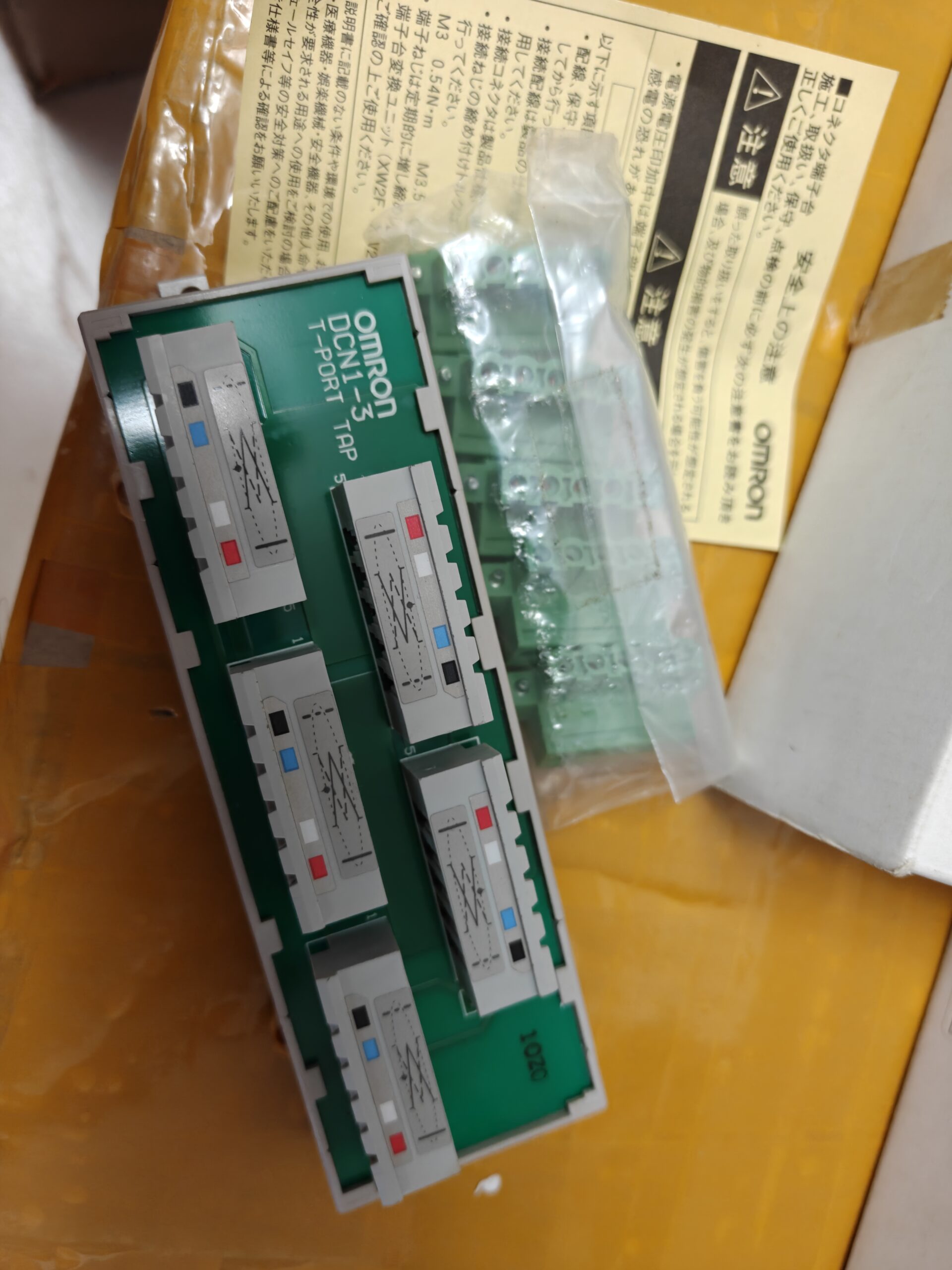

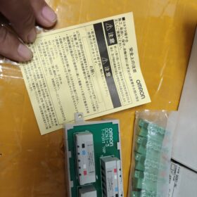
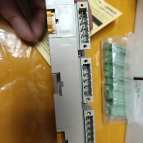
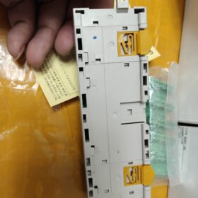
DCN13 est le nom commun du marché; les désignations officielles complètes des modèles sont DCN13C / DCN13NC. Il s'agit d'une prise Tbranch dédiée au bus de terrain à câble épais DeviceNet, utilisé pour diviser 3 nœuds de dropline de la ligne principale. Il est livré avec une résistance de terminaison intégrée de 120 Ω et appartient à Accessoires périphériques OMRON DeviceNet.
Répartition du code modèle
| Modèle | Définition du suffixe | Sens d'acheminement des câbles | Connecteur homologue |
| DCN1‑3C | C = Sortie latérale | Le câble sort horizontalement | XW4B‑05C1‑H1‑D (5 pièces) |
| DCN1‑3NC | NC = Sortie supérieure | Le câble sort vers le haut | XW4G‑05C1‑H1‑D (5 pièces) |
DCN1:Prise de branche DeviceNet T
3:Maximum 3 sorties de branche
C / Caroline du Nord:Sens de sortie du câble physique; différence mécanique seulement, électriquement identique.
Spécifications matérielles de base
| Article | Caractéristiques |
| Protocole de bus | AppareilNet (Basé sur CAN), dérivation de câble épais |
| Quantité de succursales | 3 interfaces de branche, 1-dans / 1-passage du coffre de sortie |
| Résistance de terminaison intégrée | 120 Oh (marche/arrêt configurable; les terminateurs doivent être installés aux deux extrémités physiques du tronc) |
| 5-Brochage des broches | 1: V‑; 2: CAN_L; 3: Bouclier de VIDANGE; 4: CAN_H; 5: V+ |
| Type de connecteur | Connecteur parallèle à vis, pour câble épais DeviceNet |
| Couple de serrage | 0.25-0,3N·m, tournevis dédié XW4Z‑00C |
| Certifications | UL, CE |
| Température de fonctionnement | 0-60°C; Stockage:‑25‑85°C, condensation interdite |
| Montage | Trous de montage M3; Montage sur rail DIN non pris en charge, montage par vis sur panneau sur la plaque arrière de l'armoire uniquement |
Logique de câblage
- Connectez le bus principal en amont au port IN du DCN13; connectez le port OUT pour continuer le tronc en aval.
- Connectez les lignes directes de périphériques esclaves DeviceNet au 3 ports de succursale.
- 120 Les résistances de terminaison Ω ne doivent être installées qu'aux deux extrémités physiques de l'ensemble du bus principal.. La résistance intégrée de cette prise doit être ACTIVÉE uniquement lorsque cette prise se trouve à l'extrémité physique du bus.. Pour tous les nœuds intermédiaires, le terminateur intégré DOIT être désactivé. Sinon, une résistance réseau anormale se produit (plage de résistance normale du réseau: 5070 Oh).
⚠️Symptômes de panne: Erreurs réseau, esclaves non détectés. Prioriser le dépannage: terminateurs en double, mise à la terre du bouclier, Inversion de polarité CAN_H/CAN_L.
Liste complète des séries
| Modèle | Nombre de succursales | Direction de sortie |
| DCN1‑1C / DCN1‑1NC | 1 bifurquer | Côté / Haut |
| DCN1‑2C / DCN1‑2R | 2 succursales | Côté / Angle droit |
| DCN1‑3C / DCN1‑3NC | 3 succursales | Côté / Haut |
| DCN1‑4C / DCN1‑4R | 4 succursales | Côté / Angle droit |
| DCN1‑1P | Prise d'alimentation (avec fusible) | ‑ |
Fin de vie & Informations de remplacement
- DCN13C / 3NC sont EOL (Fin de vie). L'écosystème DeviceNet est progressivement supprimé; OMRON ne fournit aucun modèle de remplacement direct de la pintopine.
- Options de migration recommandées par OMRON:
OptionA: Empilez plusieurs DCN11C (1bifurquer) des robinets pour réaliser une topologie multibranche.
OptionB: Connecteur en T scellé DCN311 (pour systèmes à câbles fins M12).
- Alternatives compatibles tierces: Des répliques de rechange du DCN13C sont disponibles. Vérifier la dimension du connecteur correspondant (XW4B05C1H1D), Terminaison 120Ω commutable et compatibilité avec les câbles épais avant l'achat.
Scénarios d'application typiques
Lignes de soudage automobile, lignes de tri pour la manutention, machines de moulage par injection. Maîtres DeviceNet PLC OMRON CS/CJseries (C200HWDRM21V1 / CJ1WDRM21) mise en réseau avec les modules d'E/S distantes de la série DRT; déploiement de nœuds esclaves multibranches sur un tronc de câble épais.
Lignes directrices pour éviter les pièges de sélection
- ❗Distinguer la série de câbles épais DCN1 de la série de câbles fins DCN3: les connecteurs sont physiquement incompatibles; ne pas mélanger.
- ❗N'activez jamais le terminateur intégré pour les nœuds de bus intermédiaires; activer uniquement les terminateurs aux deux extrémités physiques du tronc.
- ❗Utilisez uniquement un câble blindé à 5 conducteurs spécifique à DeviceNet.. Le câble CANbus générique a une impédance incompatible et entraîne une perte de paquets de communication.
- ❗Respectez un couple de serrage strict de 0,250,3N·m. Un couple excessif endommage les conducteurs du câble; un couple insuffisant provoque une communication instable.
Annexe1: Série DCN1 (Câble épais) Tableau de sélection des prises de dérivation DeviceNet
| Modèle | Nombre de succursales | Direction de sortie | Terminateur 120Ω commutable | Montage sur rail DIN | Utilisation typique |
| DCN1‑1C | 1-chemin | Côté | Oui | ❌ Montage à vis uniquement | Dérivation monopoint pour nœud de bus intermédiaire |
| DCN1‑1NC | 1-chemin | Haut | Oui | ❌ Montage à vis uniquement | Câblage à sortie supérieure pour un espace d'armoire compact |
| DCN1‑2C | 2-chemin | Côté | Oui | ❌ Montage à vis uniquement | Dérivation à proximité du site pour 2 esclaves |
| DCN1‑2R | 2-chemin | 90° Angle droit | Oui | ❌ Montage à vis uniquement | Acheminement à angle droit le long des parois latérales de l'armoire |
| DCN1‑3C | 3-chemin | Côté | Oui | ❌ Montage à vis uniquement | Nom commun DCN1‑3; branchement centralisé pour 3 nœuds |
| DCN1‑3NC | 3-chemin | Haut | Oui | ❌ Montage à vis uniquement | 3Application à nœud avec acheminement des câbles vers le haut |
| DCN1‑4C | 4-chemin | Côté | Oui | ❌ Montage à vis uniquement | Répartition centralisée pour 4 appareils esclaves |
| DCN1‑4R | 4-chemin | 90° Angle droit | Oui | ❌ Montage à vis uniquement | Câblage à angle droit haute densité |
| DCN1‑1P | 1Prise d'alimentation à sens unique | Côté | Non | ❌ Montage à vis uniquement | Prise d'alimentation bus avec fusible intégré |
Remarque importante: DCN1 = système à câble épais; DCN3 = système de câbles fins M12. Incompatibilité de prise physique; ne peut pas être mélangé dans un seul tronc.
Annexe2: Liste de contrôle de dépannage DCN13
Référence d'impédance du réseau: Avec les terminateurs activés aux deux extrémités du réseau et tous les terminateurs intermédiaires désactivés, l'impédance du bus doit être de 5 070 Ω. Plusieurs terminateurs activés diminuent l'impédance à ~ 30 Ω et déclenchent des défauts de communication.
📋 Vérification du câblage matériel
- Vérifier l'affectation des 5 broches (se référer au schéma de brochage):
Broche1: Alimentation négative du bus V
Broche2: CAN_L
Broche3: BOUCLIER Vidange
Broche4: CAN_H
Broche5: Alimentation bus V+ 24V
✅ Interdit: CAN_H / Inversion CAN_L; V+ / Inversion de polarité V - détruira le matériel esclave.
- Couple de serrage des vis des bornes: 0.250.3 N·m. Le surcouple rompt les conducteurs; undertorque creates intermittent contactrelated packet loss.
- Shieldhandling: Connect Pin 3 shield drain to ground at one single point only. Multiple grounding points create groundloop interference and frequent communication errors.
📋 TerminatingResistor Troubleshooting (Highestprobability fault source)
- Tapmount toggle switch: Enable the internal 120 Ω terminator ONLY if this tap sits at the absolute physical end of the DeviceNet trunk. Disable for all intermediate nodes.
- The entire trunk shall have exactly two terminators, fitted at the two physical trunk extremities.
- Multimeter measurement between CAN_H / CAN_L:
Terminator ON at both ends, all intermediate terminators OFF: 5070 Ω ✔ OK
Multiple terminators enabled: <40 Ω ❌ Fault
Both end terminators OFF: Résistance infinie ❌ Terminaison manquante
📋 Phénomènes de panne, Causes profondes & Remèdes
| Phénomène de défaut | Cause profonde probable | Mesure corrective |
| L'automate ne parvient pas à détecter tous les esclaves | Terminateurs en double; CAN_H/CAN_L inversé; perte d'alimentation 24V du bus | Vérifier les commutateurs de terminaison; valider le brochage; mesurer V+/V‑ (21-24 V CC) |
| Abandon aléatoire et intermittent des esclaves partiels | Mauvais sertissage/couple; mise à la terre du blindage multipoint; inadéquation d'impédance de câble; acheminement à côté des câbles d'alimentation | Et les terminaux; mise à la terre du blindage en un seul point; utilisez un véritable câble DeviceNet; séparé des câbles d'alimentation |
| Matériel esclave endommagé immédiatement après la mise sous tension | Autobus V+ / Polarité V inversée | Mise hors tension, valider la broche 1 / polarité de la broche 5; remplacer les esclaves endommagés |
| Analyse réseau OK, erreurs fréquentes de données d'E/S | La longueur de la ligne de chute dépasse les spécifications; topologies mixtes de câbles épais/fins | Longueur maximale de la ligne de descente pour un tronc de câble épais: 6m. Ne connectez pas le matériel à câble épais DCN1 directement aux appareils à câble fin DCN3 M12.. |
⚠️ Interdictions de contraintes dures
- ❌ Le montage sur rail DIN est interdit. Montage uniquement via des vis M3 sur la plaque arrière.
- ❌ Le câble CANopen générique ne peut pas remplacer le câble DeviceNet; inadéquation d'impédance.
- ❌ La longueur des lignes de chute individuelles ne doit pas dépasser 6 m. Longueur maximale du tronc par rapport au débit en bauds: 500 kbit/s=100 millions; 250 kbps=250 millions; 125 kbps=500 millions.
- ❌ N'activez jamais le terminateur interne du robinet lorsque le robinet est situé sur un nœud Cabinetbus intermédiaire..
Annexe3: Recommandations de mise à niveau EOL
DCN13C/DCN13NC sont EOL; OMRON n'offre aucun remplacement instantané.
- Option de mise à niveau1: Déployez plusieurs prises DCN11C pour le câblage distribué tout en conservant l'infrastructure de câbles épais d'origine. (pièces de rechange encore disponibles).
- Option de mise à niveau2: Migration complète du système vers la topologie Thincable M12 de la série DCN3; tous les connecteurs maître/esclave doivent être remplacés, surcharge de modification matérielle élevée.
- Notes d'achat de pièces tierces compatibles: Confirmer l'attribution des broches, terminateur 120Ω commutable, compatibilité avec le calibre de conducteur à câble épais DeviceNet.
OMRON DCN13 (DCN13C / DCN13NC) Scénarios d'application
DCN13 est une dérivation en T à câble épais DeviceNet avec 3 sorties de branche. Valeur fondamentale: dériver trois droplines à partir d'un seul emplacement sur le tronc de câble épais pour les E/S distantes, capteurs, lecteurs et autres périphériques esclaves. Optimisé pour le déploiement centralisé de plusieurs nœuds à l'intérieur des machines / armoires de commande. Strictement réservé aux systèmes de lignes principales à câbles épais; incompatible avec le matériel Thincable DCN3 M12.
Cas d'utilisation typiques de l'industrie
- Lignes de production de soudage automobile (Déploiement le plus courant)
Architecture réseau: OMRON CJ1WDRM21 / API CSseries comme maître DeviceNet; tronc de câble épais acheminé le long des postes de soudage.
Utilisation du DCN13: Une station héberge trois E/S distantes série DRT, îlots de vannes ou contrôleurs de soudage. Un DCN13 fournit trois lignes directes locales, éliminant plusieurs Ttaps en cascade et réduisant le nombre total de connecteurs de bus et les points de défaillance de communication.
Contraintes: Chaque dropline individuelle ≤6m. Robinet fixé à la plaque arrière de l'armoire de station avec des vis M3.
- Manutention des matériaux & Systèmes de convoyeurs
Équipement: Convoyeurs à rouleaux, mécanismes de transfert de tri, cylindres de blocage, détecteurs photoélectriques.
Application: Une ligne principale passe à côté d'une navette de tri / unité de transfert avec trois nœuds d'E/S distantes simultanées. DCN13 implémente un branchement centralisé pour DR2 / Modules d'E/S esclaves DRT DeviceNet.
Avantage: Réduit l'encombrement des câbles internes de l'armoire par rapport aux multiples prises monobranches DCN11.
- Moulage par injection & Machines d'extrusion
Réseautage: Le bus DeviceNet à l'intérieur de la machine de moulage connecte les modules d'entrée de température, entraînements de vannes proportionnelles et modules d'entrée de sécurité.
Placement: Acheminement du coffre à l'intérieur de l'armoire de commande; branchement local pour trois appareils esclaves colocalisés.
Note: Environnement à bruit électrique élevé à l'intérieur des machines d'injection. Le drain du bouclier doit être mis à la terre en un seul point; mise à la terre multipoint interdite.
- Machines d'emballage (Nourriture & Emballage pharmaceutique)
Machines: Emballeurs de caisses, palettiseurs, machines à sceller.
Scénario: Trois ensembles d'esclaves DeviceNet (îlots de vannes, E/S de détection) regroupés sur un côté du meuble; DCN13 pour une dérivation concentrée.
Limites environnementales: Température de fonctionnement 060°C. Ne convient pas aux environnements à forte condensation ou à atmosphère corrosive.
- Machines-outils & Machines d'automatisation spécialisées sur mesure
Postes de travail de montage et d'outillage: Trois nœuds esclaves d'acquisition de signal sur un poste de travail où passe le tronc de câble épais. DCN13 pour le branchement local.
Note: Éviter l'exposition directe au liquide de coupe des machines-outils; installer à l'intérieur de l'enceinte de protection.
Niveau du Cabinet / Scénarios de topologie montés sur machine
- Dérivation centralisée à l'intérieur de l'armoire de commande
Le tronc de câble épais DeviceNet traverse l'armoire. Trois modules esclaves résident à l'intérieur de l'armoire. DCN13 fixé sur la plaque arrière de l'armoire: IN pour le réseau en amont, OUT continue le tronc en aval; trois ports de branchement se connectent à trois appareils esclaves.
Lorsque DCN13 n'est pas à l'extrémité physique du réseau: la terminaison interne de 120 Ω doit être éteinte.
- Monté à l'intérieur d'une boîte de jonction de terrain
Le câble principal entre dans une boîte de jonction classée sur le terrain; trois lignes de descente se dirigent vers les îlots de vannes de terrain / Modules d'E/S. Le robinet lui-même n'a pas d'indice IP; doit être entièrement enfermé dans une boîte de jonction protectrice, jamais exposé à l'extérieur.
Scénarios non applicables (Avertissements de sélection)
- ❌ Câble mince DeviceNet (M12) systèmes: DCN13 est un câble épais uniquement, matériel incompatible avec la série DCN3; ne pas mélanger.
- ❌ Emplacement Trunkend nécessitant uniquement 12 nœuds: Préférez DCN11C / DCN12C, éviter de trop spécifier DCN13.
- ❌ Longueur de la ligne de chute individuelle > 6 m: Limite stricte de la ligne de chute de câble épais DeviceNet; la trop grande longueur déstabilise le réseau.
- ❌Installation extérieure, pulvérisation directe de fluide, forte condensation, atmosphère corrosive.
- ❌ Montage direct sur rail DIN: Pas de matériel DINclip; seul le montage sur vis de panneau M3 est autorisé.
- ❌ Utilisation du bus CANopen: Connecteur physique similaire, couche de protocole incompatible; ne peut pas fonctionner sur les réseaux CANopen.
Nomenclature de référence pour le matériel correspondant
Unités maîtres API: CJ1WDRM21, C200HWDRM21V1
E/S esclave: IDDRT2, DRT2OD, E/S distantes série DRT2MD
Îlots de vannes: Ilot de vannes SMC DeviceNet, Îlot d'alarme Festo DeviceNet
Câble: Câble épais blindé à 5 conducteurs spécifique à DeviceNet
OMRON DCN13 (DCN13C / DCN13NC) Instructions d'installation
⚠️ Critique: Le DCN13 n'a pas de clip rail DIN. Le montage direct sur rail DIN n'est pas pris en charge. Montage sur vis uniquement.
- Spécifications d'installation mécanique
| Article | Valeur |
| Style de montage | Montage sur panneau sur plaque arrière d'armoire / panneau de montage |
| Trous de montage | 2 × Trous traversants de Φ3,5 mm pour vis M3 |
| Fixations recommandées | Vis à tête cylindrique M3 |
| Couple de serrage du corps de l'appareil | 0.4‑0,5N·m. Ne pas trop serrer pour éviter la fissuration du boîtier. |
| Dimension globale (DCN1‑3C) | 142(L) × 45(W) × 31.3(D) mm |
| Orientation de montage | Arbitraire (horizontal / verticale). Réservez un espace suffisant pour la manipulation des câbles et l'accès aux tournevis.. |
Différence de routage mécanique: DCN13C contre DCN13NC
- DCN13C (C = Sortie latérale)
Les câbles sortent horizontalement du côté de l'unité. Convient pour un montage à plat sur une plaque arrière d'armoire avec un acheminement horizontal des câbles.
- DCN13NC (NC = Sortie supérieure)
Les câbles sortent verticalement vers le haut depuis le haut de l'unité. Utilisé lorsque l'emplacement d'installation a un dégagement inférieur limité.
Les performances électriques sont identiques; la sélection dépend uniquement de la géométrie du routage des câbles sur le terrain.
- Procédure d'installation standard
- Percez deux trous de montage de Φ3,5 mm sur la plaque arrière de l'armoire conformément au dessin dimensionnel.
- Fixez le corps du DCN13 à la plaque arrière de l'armoire avec des vis M3.; couple 0,40,5N·m.
- Réservez un espace tout autour pour l'accès au connecteur et le fonctionnement du tournevis..
- Terminer les câbles épais DeviceNet:
DANS: Bus interurbain amont; DEHORS: Continuer le bus principal en aval.
Les trois ports restants connectent les lignes directes aux appareils esclaves respectifs.
Couple de vis de la borne du connecteur = 0,250,3 N·m. Le surcouple endommage les brins de câble; le sous-couple provoque des défauts de communication intermittents.
- Configurez l'interrupteur à bascule du terminateur 120 Ω intégré:
Robinet situé sur le nœud de bus intermédiaire → TerminatorOFF.
Prise située à l'extrémité physique absolue du bus réseau → TerminatorON.
- Câblage du blindage: Broche3 (BOUCLIER/DRAIN) connecté à la terre de protection en un seul point de terre. Mise à la terre multipoint interdite pour éviter le bruit de la boucle de terre.
- Exigences relatives à l'emplacement d'installation
- ✅ Environnements acceptables: Plaque arrière intérieure de l'armoire de commande; à l'intérieur de la boîte de jonction de protection; température ambiante060°C, sans condensation.
- ❌ Conditions d'installation interdites:
Montage direct sur rail DIN (le cerclage avec des serre-câbles entraîne un desserrage induit par les vibrations et des défauts intermittents).
Montage extérieur exposé, pulvérisation de liquide de coupe directe.
Montage à proximité immédiate des VFD, contacteurs et composants haute puissance; maintenir un dégagement pour l'atténuation du bruit.
Compartiments confinés scellés entraînant une élévation de température supérieure à 60°C.
- Contraintes de câblage topologique dur (Doit être suivi pour l’installation du matériel)
- Longueur maximale de la ligne de chute individuelle: 6 m limite absolue pour le système à câble épais. Des lignes directes plus longues dégradent la stabilité du réseau.
- Longueur maximale de la ligne principale par rapport au débit en bauds:
500 kbps: 100 m maximum
250 kbps: 250 m maximum
125 kbps: 500 m maximum
- Exactement deux terminateurs de 120 Ω doivent être activés aux deux extrémités physiques du bus principal. Tous les terminateurs de prise de nœud intermédiaire doivent rester désactivés.
- Erreurs d'installation courantes & Pièges
- ❌ Fixation de l'unité au rail DIN uniquement avec des serre-câbles: Les vibrations desserrent l'assemblage, déclenche des interruptions aléatoires du réseau.
- ❌ Couple de vis de borne excessif: L'écrasement des conducteurs crée des défauts latents et intermittents.
- ❌ Mise à la terre du blindage à plusieurs points: Erreurs de communication haute fréquence et perte de paquets.
- ❌ Activation accidentelle du terminateur intégré lorsque le robinet se trouve sur le nœud de bus d'armoire intermédiaire: Faible impédance du réseau.
- ❌ Longueur de dropline supérieure à 6 m.
- Installation de scénarios spéciaux
Montage sur boîte de jonction: DCN13 sécurisé à l'intérieur d'une boîte de jonction IP. Le robinet lui-même n'a aucun indice de protection de l'environnement et ne doit jamais être exposé.
Armoires compactes: Préférez le modèle à sortie supérieure DCN13NC pour réduire les interférences des câbles horizontaux.





NH42-63-318x560.png "Commutateurs de transfert automatiques de type PC CHINT (ATS)NH42-63/4SZ")



