 Contacteur,disjoncteur,capteur,Encodeur,API,Convertisseur

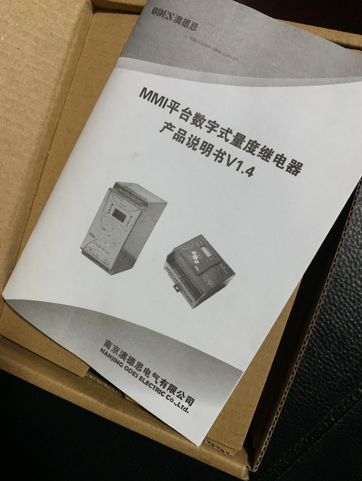

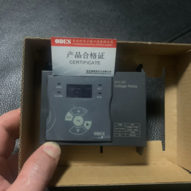
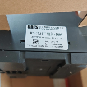

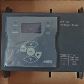
WY-30 = tension alternative numérique Relais de surveillance (Relais de protection de tension)
Marque: ODE (AoDesi / Xieao Intelligent)
Positionnement: Relais de protection du système électrique, Montage sur rail DIN, équipé d'un écran LCD, supporte les surtensions / surveillance des sous-tensions et réglage de la temporisation réglable.
Règle de codage du modèle (WY-XXAX□)
Wyoming: Relais de tension numérique
3: Plateforme matérielle EMG32 (Série WY-30)
1: Surélément (Relais de surtension)
5: Sous-élément (Relais de sous-tension)
UN: Tension de mesure: 100 ACC (largement utilisé pour les circuits secondaires PT)
C: Tension de mesure: 400 ACC
Dernier chiffre 1 / 4: 1=Monophasé; 4=Triphasé
Modèles complets courants:
WY-31A1 (Surtension monophasée), WY-35A1 (Sous-tension monophasée), WY-31A4 (Surtension triphasée), WY-35A4 (Sous-tension triphasée)
Principales spécifications techniques
- Circuit de mesure
Entrée nominale: 100 ACC / 400 ACC; 50 Hz (60 Hz disponible sur demande)
Consommation d'énergie: ≤0,5VA
- Alimentation auxiliaire (Large gamme universelle)
C.A. 85 ~ 265 V / C.C 88 ~ 370 V
- Contacts de sortie
2 jeux de contacts inverseurs (2DPDT)
Évaluation des contacts: 6 UN / 250 ACC; 6 UN / 30 VCC
- Plage de réglage réglable
Tension de fonctionnement: Réglable en continu
Temporisation du temps de fonctionnement: 0~10 s (extensible)
- Montage
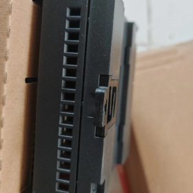
Montage sur rail standard DIN35
Dimension hors tout: 96(L) ×90(W) ×65,3(H) mm
- Niveau CEM: Classe IV, adapté aux sous-stations et aux appareillages de puissance auxiliaire
Fonctions principales
Monophasé en temps réel / surveillance de la tension alternative triphasée avec affichage de la tension LCD
Protection contre les surtensions, blocage de sous-tension
Alarme de perte de tension PT, surveillance de la tension du jeu de barres
Fonction anti-perturbation temporisée pour éviter les dysfonctionnements causés par des fluctuations transitoires
Verrouillage par mot de passe des paramètres pour empêcher toute modification non autorisée
Indicateur de fonctionnement ACT pour indication de phase de défaut
Scénarios d'application typiques
Panneaux de protection pour générateurs et transformateurs
Haut & appareillage basse tension, systèmes d'alimentation auxiliaires
Surveillance du circuit de tension PT et alarme de perte de tension
Protection de tension pour le raccordement au réseau photovoltaïque et éolien
Surveillance de la tension alternative adaptée aux systèmes DC dans les sous-stations
Produits homologues au sein de la même série
WY-30: Relais de tension (modèle de sujet)
WL-30: Relais de surveillance du courant
Série WT: Relais de contrôle de synchronisme
Spécifications de précision pour le relais de tension série ODES WY-30
- Précision de mesure de tension
Erreur de mesure de tension: ±3% (par rapport à la tension d'entrée nominale Un)
Applicable à tous les modèles: WY-31A1 / WY-35A4 / WY-31C4 et autres variantes du WY-30
- Précision du délai de fonctionnement
Plage de réglage du retard: 0 ms ~ 9999 ms
Erreur de temporisation: ±(1% de la valeur réglée + 60 MS)
- Autres indicateurs clés
Rapport de réinitialisation: Type de surtension = 0.9; Type de sous-tension = 1.1 (personnalisable sur demande spéciale)
Spécification d'entrée: 100 ACC / 200 ACC / 400 ACC, 50 Hz
Plage de température de fonctionnement: -40℃ ~ + 70 ℃; les indicateurs de précision restent valables dans cette plage
Notes complémentaires
- Cet appareil est un composant de surveillance de protection, ce n'est pas un instrument de mesure. Avec une précision de classe de protection de ±3 %, il répond aux exigences standard en matière de supervision de l'alimentation auxiliaire, Surveillance des circuits PT et protection de la tension de connexion au réseau.
- Si une précision plus élevée (Classe 0.5 / Classe 0.2 mesure) est requis sur place, des compteurs de puissance multifonctions doivent être adoptés. Les lectures du WY-30 ne peuvent pas être utilisées pour la mesure du tassement énergétique.
Principe de fonctionnement du relais de surveillance de tension numérique ODES WY-30
Le WY-30 est un système de surveillance numérique de la tension alternative à échantillonnage basé sur MCU. & relais de protection. Sa fonction essentielle: échantillonner en continu la tension alternative, comparer la valeur mesurée aux seuils prédéfinis, et sortie de contact de relais d'entraînement lorsque les conditions sont satisfaites pour réaliser une surtension, surveillance des sous-tensions et des pertes de tension PT.
- Flux de signaux matériels
- Circuit d'entrée de tension
Monophasé externe / tension alternative triphasée (100 VAC PT secondaire ou 400 Tension du bus VCA) est connecté aux bornes de mesure.
Un transformateur de tension de précision miniature intégré isole et abaisse les signaux CA haute tension en signaux de bas niveau., réaliser une isolation électrique entre les circuits forts et faibles pour protéger le circuit de commande principal.
- Circuit de conditionnement du signal
Le signal alternatif sinusoïdal abaissé subit un filtrage → adaptation d'impédance → rectification de décalage, converti en forme d'onde de tension analogique continue adaptée à l'échantillonnage MCU ADC.
- Unité de contrôle principale MCU (Cœur)
Équipé d'un ADC haute vitesse; échantillonne périodiquement les valeurs instantanées de la tension alternative.
L'algorithme logiciel intégré calcule le True RMS (Moyenne quadratique) Tension alternative, qui est insensible à une légère distorsion de la forme d’onde.
⚠️ Caractéristique clé: Adopte le calcul RMS au lieu d'une simple conversion de crête, applicable aux réseaux électriques déformés tels que les systèmes d'alimentation auxiliaires et les connexions au réseau d'énergie renouvelable.
- Stockage des paramètres & Interface Homme-Machine
L'écran LCD affiche la tension du bus en temps réel;
Les utilisateurs configurent le seuil de surtension, seuil de sous-tension, critères de retard de fonctionnement et de perte de tension via le clavier. Les paramètres sont stockés dans une mémoire non volatile, conservé après une panne de courant, et prend en charge le verrouillage par mot de passe.
- Jugement logique & Logique de protection
Le MCU compare en permanence la tension mesurée avec la valeur de fonctionnement définie par l'utilisateur par cycles.
WY-31xx (Type de surtension)
Tension mesurée ≥ Réglage de surtension → la minuterie démarre;
Si le défaut persiste à l'expiration du délai → le relais s'active;
La tension chute en dessous de la valeur de réinitialisation → le relais se réinitialise automatiquement.
WY-35xx (Type de sous-tension)
Tension mesurée ≤ réglage de sous-tension → la minuterie démarre;
Si la condition de sous-tension persiste après le délai → le contact s'actionne;
La tension dépasse le seuil de réinitialisation → réinitialisation automatique.
Taux de réinitialisation par défaut d'usine: Surtension = 0.9; Sous-tension = 1.1
- Circuit de sortie relais
Le MCU transmet un signal de conduite de bas niveau pour contrôler le relais électromagnétique embarqué (2 jeux de contacts inverseurs).
Les contacts passifs sont câblés à des circuits de commande externes pour l'alarme, déclenchement et verrouillage.
- Séquence de fonctionnement complète (Exemple de protection contre les sous-tensions)
- Fonctionnement normal: La tension reste dans la plage de seuil → le relais reste à l'état normal hors tension;
- La tension du bus chute en dessous du réglage de sous-tension;
- La minuterie interne est déclenchée (pour éviter les dysfonctionnements causés par une chute de tension instantanée);
- Si la tension récupère pendant la période de retard → la minuterie se réinitialise, pas d'opération;
- La sous-tension persiste après l'expiration du délai → le contact du relais commute l'état pour déclencher une alarme externe ou une commande de déclenchement;
- La tension revient au-dessus de la valeur de réinitialisation → le relais se réinitialise automatiquement.
III. Logique de perte de tension PT intégrée (Caractéristique standard pour les modèles triphasés)
Les variantes triphasées mettent en œuvre une logique de jugement de perte de phase:
Lorsqu'une ou plusieurs phases détectent une tension proche de zéro alors que les phases restantes affichent une tension normale, le relais identifie cette condition comme une coupure de circuit PT / perte de tension. Une temporisation indépendante et une logique de sortie peuvent être configurées pour distinguer une véritable sous-tension du jeu de barres d'une défaillance du circuit de tension., prévenir les dysfonctionnements de la protection.
- Mécanisme d'alimentation auxiliaire
Alimentation de fonctionnement de l'appareil: C.A. 85 ~ 265 V / Entrée large plage DC 88 ~ 370 V.
Le module d'alimentation interne génère plusieurs alimentations CC stabilisées pour le MCU, circuit d'échantillonnage, affichage et commande de relais.
Important: Le circuit de mesure de tension et le circuit d'alimentation auxiliaire sont mutuellement indépendants. Le relais alimenté ne garantit pas une mesure de tension valide.
- Résumé du principe (Directement utilisable dans les propositions techniques)
Le relais de tension ODES WY-30 échantillonne la tension du bus CA via un transformateur d'isolation intégré et calcule la vraie tension efficace via l'échantillonnage ADC.. Le microcontrôleur compare en permanence la tension mesurée aux seuils configurés avec une logique anti-bruit à temporisation. En cas de surtension, des défauts de sous-tension ou de perte de tension PT se produisent, les contacts de relais passifs sont activés pour émettre des signaux de commutation pour la surveillance des anomalies de tension, protection d'alarme et de verrouillage. Il est largement appliqué dans les systèmes d'alimentation auxiliaire des appareillages de commutation., Circuits secondaires PT et surveillance de la tension pour la connexion au réseau de production distribuée.





NH42-63-318x560.png "Commutateurs de transfert automatiques de type PC CHINT (ATS)NH42-63/4SZ")



