 Contacteur,disjoncteur,capteur,Encodeur,API,Convertisseur

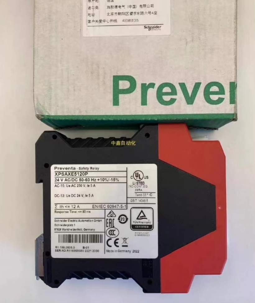

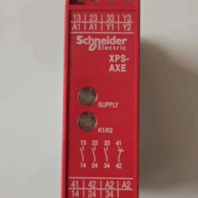
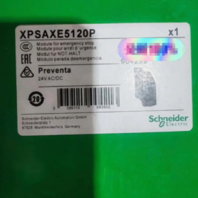
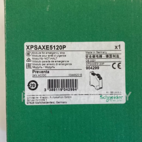
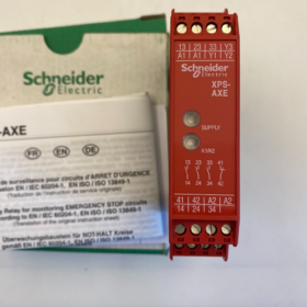
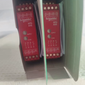
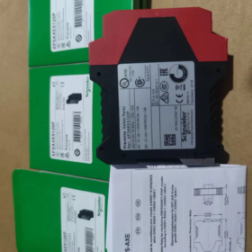
Positionnement du produit: Safety module for emergency stop & surveillance des interrupteurs de barrière de sécurité (Catégorie 0 arrêt). Replacement for legacy XPSAX
Modèles typiques: XPSAXE5120P / XPSAXE5120C
XPSAXE5120P: Bornes à vis amovibles
XPSAXE5120C: Removable spring terminals
Alimentation: 24 V CA/CC (CA & CC universel)
Montage: 35 mm rail DIN, largeur 22.5 mm
Dimensions hors tout (L×H×P): 22.5 × 99 × 114 mm
✅ Safety Ratings
PL e / Cat.4 (EN ISO 13849-1)|SIL CL3 (CEI 61508 / CEI 62061)
Normes applicables: EN ISO 13850 (Arrêt d'urgence), EN ISO 14119 (Safety Interlock Switches)
- Canal & Définition du terminal (XPSAXE5120)
1) Alimentation
A1, A2: Module power supply, 24 V CA/CC
2) Safety Inputs (Dual-channel monitoring, dual NC emergency stop / safety switches recommended)
S11-S12: Canal 1
S21-S22: Canal 2
Detects short circuits and wire breaks between dual channels; synchronous response window between channels <0.5 s
3) Start Circuit (Réinitialiser)
S33, S34
Short S33 and S34 → Automatic Reset
Connect external NO pushbutton between S33 and S34 → Manual Reset
4) External Contactor Feedback Circuit (Obligatoire!)
Y1, Y2
Câbler les contacts NC auxiliaires du contacteur du circuit principal en série sur Y1-Y2;
Fonction: Empêcher le démarrage inattendu de la machine si les contacteurs soudent fermés (protection anti-rebond contre le redémarrage).
5) Sorties de sécurité (3 jeux de contacts de sécurité instantanés NO)
13-14, 23-24, 33-34
Trois indépendants relais de sécurité contacts pour la mise hors tension des bobines des contacteurs de puissance.
Courant nominal à contact unique: 6 UN; AC-15: 360 VA charge continue; DC-13: 24 V/1,5A.
6) Sortie de signal API auxiliaire (Circuit non sécurisé!)
41-42: 1 jeu de contacts de signal NF
Utilisé uniquement pour le retour d'état vers l'automate. Strictement interdit pour les circuits de coupure de sécurité.
7) Indicateurs LED
REP: Alimentation présente
COURIR: Circuit de sécurité fermé, sorties excitées
- Logique de fonctionnement
- Allumer; réinitialisation de l'arrêt d'urgence & barrière de sécurité fermée → S11-S12 / Conducteur S21-S22
- Circuit de retour Y1-Y2 fermé (contacteur principal hors tension)
- Appuyez sur le bouton de réinitialisation (ou réinitialisation automatique active) → les doubles relais internes sont alimentés
- 13-14 / 23-24 / 33-34 fermer, utilisation de la machine autorisée
- Arrêt d'urgence déclenché / porte ouverte / défaut de câblage détecté → trois sorties de sécurité ouvertes instantanément (≤80 ms)
- La réinitialisation est bloquée jusqu'à ce que tous les défauts soient effacés
- Schémas de câblage typiques recommandés
- Schéma standard (Arrêt d'urgence double NC + Réinitialisation manuelle + Retour)
A1/A2: 24 Alimentation V
Arrêt d'urgence double NC: Alimentation électrique commune, deux canaux acheminés séparément vers S11-S12 et S21-S22
AUCUN bouton-poussoir de démarrage câblé entre S33 et S34
Contacts auxiliaires NC du contacteur d'alimentation principal câblés en série à Y1-Y2
13/23/33 connecté à l'alimentation; 14/24/34 câblé en parallèle pour entraîner la bobine du contacteur principal
- Pratiques interdites
Ne PAS utiliser 41-42 contacts de signal pour coupure de sécurité
N'omettez PAS le circuit de rétroaction Y1-Y2 (pertes protection anti-soudure, ne peut pas atteindre la catégorie 4)
Le câblage monocanal atteint uniquement PL d/Cat.3, ne répond pas aux exigences des machines haut de gamme
- Notes clés pour le remplacement de l'ancien XPSAX (Application commune)
Modèle hérité: XPSAX5120 → Remplacer par XPSAXE5120P
- Les affectations des bornes ne sont pas entièrement compatibles broche à broche, le remplacement direct de la fiche est impossible; le câblage des bornes doit être revérifié
- XPSAXE adopte des bornes amovibles pour faciliter le câblage et la maintenance de l'armoire
- Dimension en hauteur augmentée; vérifier l'espace d'installation disponible
- Logique de fonctionnement et cote de sécurité identiques
- Référence de comparaison de sélection de série
XPS-AXE: Arrêt d'urgence / surveillance des barrières de sécurité, 3 AUCUNE sortie de sécurité, avec commentaires; Catégorie 0 arrêt
XPS-AC: Compact 22.5 mm largeur, fonctions similaires avec des différences mineures de capacité de charge
XPS-AK: Prend en charge les barrières immatérielles de sécurité, tapis de sécurité; fonctions améliorées, coût plus élevé
- Dépannage courant
- LED RUN éteinte après la mise sous tension
Vérifiez que S11/S21 les deux canaux sont conducteurs
Vérifier la continuité de Y1-Y2 (confirmer que le contacteur n'est pas soudé)
- La machine ne peut pas redémarrer après le déclenchement de l'arrêt d'urgence
Confirmer le mode de réinitialisation: courts S33 et S34 pour une réinitialisation automatique
Court-circuit ou rupture de fil détecté dans les canaux à double entrée
- Déclenchement aléatoire pendant le fonctionnement
Total wiring resistance of input cables exceeds limit (≤50 Ω); use larger cross-section cables for long wiring runs
je peux fournir:
✅ Text version of standard wiring schematic
✅ Full datasheet parameters of XPSAXE5120P
✅ Terminal comparison table: XPSAX vs XPSAXE
Application Scenarios of Schneider XPS-AXE (XPSAXE5120P/C) Relais de sécurité
Core Position Recap
Only supports two safety input types: dual-channel dual NC emergency stop pushbuttons + safety gate interlock switches
Cote de sécurité: PL e / Cat.4, SIL CL3, Catégorie 0 instantaneous power cut-off
Not compatible with: Barrières immatérielles de sécurité, tapis de sécurité, two-hand control devices;
Configuration standard: External contactor feedback circuit (Y1-Y2), 3 safety NO outputs, 1 PLC status signal output; supports Manual Reset / Réinitialisation automatique.
- Supported Safety Functions
- Emergency Stop Circuit Monitoring (OIN 13850) : Monitoring machine main emergency stop and zone emergency stop via dual channels
- Safety Guard Door Interlock Monitoring (OIN 14119) : Clôtures mécaniques, portes d'accès, interrupteurs de verrouillage du capot de protection
Commutateurs applicables: Doubles interrupteurs de barrière de sécurité NC, interrupteurs de verrouillage de sécurité magnétiques (Contacts NF)
- Applications typiques de l'industrie
1) Machines-outils générales & Équipement de travail des métaux
Tours CNC, centres d'usinage, fraiseuses, broyeurs
Petites presses, machines hydrauliques, presses plieuses, cisailles
Machines à découper, broyeurs, équipement d'ébavurage
Usage: Arrêt d'urgence du panneau de la machine + porte d'armoire électrique / verrouillage du capot de protection
2) Conditionnement, Impression & Machines pour le caoutchouc/plastique
Machines verticales de formage/remplissage/scellage, flow wrappers, emballeurs de caisses, équipement auxiliaire de palettisation
Machines de soufflage, équipement auxiliaire de moulage par injection, petites lignes d'extrusion
Machines à imprimer, plastifieuses, découpeuses
Caractéristiques: Risque de pincement entre les rouleaux et les convoyeurs; arrêt immédiat de la machine requis dès l'ouverture de la porte de protection
3) Convoyage & Équipement d'automatisation logistique
Convoyeurs à bande, convoyeurs à rouleaux, unités de transfert, tables de transfert élévatrices
Petits systèmes de stockage automatisés, postes de tri, unités individuelles sur lignes de conditionnement
Verrouillage de la barrière de protection aux coins du convoyeur à rouleaux
4) Petites cellules de travail robotisées
Robots compacts 6 axes, Clôture de sécurité monobloc robot SCARA
⚠️ Limitation: Uniquement pour porte de clôture + surveillance d'arrêt d'urgence du poste de travail. Relais de sécurité XPS-AK supplémentaire requis si des barrières immatérielles de sécurité sont déployées.
5) Nourriture & Équipement d'emballage pharmaceutique
Machines de remplissage, machines à capsuler, étiqueteuses, équipement auxiliaire de stérilisation
Machines autonomes de découpe des aliments et de manutention des matériaux
Avantages: 24 Alimentation à large plage V AC/DC, montage sur rail DIN compact; répond aux exigences CE pour les machines d'exportation
6) Travail du bois & Machines de traitement des composites
Plaqueuses de chants, Routeurs CNC emboîtables, machines à graver, ponceuses
Découpe de panneaux, petit équipement de presse à chaud composite
7) Bancs d'essais & Machines d'automatisation personnalisées
Stations de tests d'étanchéité à l'air des composants, machines personnalisées à ajustement serré, équipement de serrage au couple
Petit équipement d'assemblage de batteries au lithium, outillage d'inspection
Largement adopté pour la construction de circuits de sécurité sur des machines personnalisées afin de satisfaire à la directive européenne sur les machines & Marquage CE
- Schémas d'application de câblage typiques
- Schéma A: Machine unique avec arrêt d'urgence + Barrière de sécurité (Le plus courant)
Deux canaux câblés en série: Arrêt d'urgence double NC + barrière de sécurité double NC. La machine s'arrête immédiatement après l'activation de l'un ou l'autre des appareils.
Convient aux équipements autonomes équipés de capots de protection et de barrières de sécurité.
- Schéma B: Surveillance d'arrêt d'urgence à double canal uniquement
Les deux canaux sont connectés à un arrêt d'urgence double NC sans protecteur mobile; utilisé pour les équipements à châssis ouvert uniquement équipés d'une protection d'arrêt d'urgence.
- Schéma C: Surveillance des portes de protection uniquement
Deux canaux connectés aux interrupteurs des barrières de sécurité, travailler avec des arrêts d'urgence de zone pour former le système complet de sécurité de la machine.
- Applications inappropriées (Pièges de sélection)
- Interface requise avec les barrières immatérielles de sécurité, tapis de sécurité, bords de sécurité → Sélectionnez XPS-AK / XPSUAK
- Arrêt temporisé requis (Catégorie1/2 arrêt) → Série temporisée XPS-ATE
- Fonction de commande bimanuelle requise → XPS-AB
- Mélange de plusieurs signaux de sécurité (rideau lumineux + barrière de sécurité + arrêt d'urgence) → Module de sécurité universel XPSUAF
- Sorties de sécurité statiques requises (pas de contacts mécaniques) → Modèles avec sorties semi-conductrices
- Rappels de sélection des clés
Remplacement direct de l'ancien XPSAX5120: XPSAXE5120P (bornes à vis) / XPSAXE5120C (bornes à ressort)
Alternative à une armoire compacte avec des fonctions équivalentes: Comparez XPSAC5121
Pour atteindre la cote de sécurité Cat.4, Le circuit de retour du contacteur Y1-Y2 ne peut pas être omis
je peux organiser:
✅ Version texte du schéma de câblage standard XPSAXE
✅ Texte de description de la fonction de sécurité pour l'évaluation des risques CE (directement utilisable dans les manuels des machines)
Analyse détaillée du circuit de retour de contacteur externe Y1-Y2 pour Schneider XPS-AXE (XPSAXE)
Bornes Y1, Y2
Connecter l'auxiliaire normalement fermé (Caroline du Nord) contacts des contacteurs de puissance principaux
⚠️ Ce circuit ne doit pas être omis pour atteindre le PL e / Cat.4
- Quatre fonctions principales
1) Protection des contacteurs anti-soudure (Le plus critique)
Scénario: La soudure des contacts principaux du contacteur principal est fermée en raison d'une ablation à courant élevé ou d'un blocage mécanique..
Arrêt normal: Bobine du contacteur hors tension, principaux contacts ouverts; les contacts auxiliaires NC rétablissent l'état fermé, Conducteur Y1-Y2.
Condition de défaut de soudure: Le relais de sécurité coupe les sorties, mais le circuit d'alimentation principal reste sous tension; les contacts auxiliaires NC restent ouverts → le circuit Y1-Y2 s'ouvre.
XPS-AXE détecte un circuit Y1-Y2 ouvert, verrouille le système de sécurité et bloque la réinitialisation, empêchant les démarrages inattendus de la machine et les risques graves pour la sécurité.
- Surveillance de sécurité en boucle fermée conforme à la norme EN ISO 13849 Cat.4
La norme de sécurité Cat.4 exige que le système détecte les défauts de ses actionneurs (contacteurs).
Si le retour Y1-Y2 est omis:
La cote de sécurité est rétrogradée à PL d / Cat.3, exigences insuffisantes en matière de machines haut de gamme et de certification CE à l'exportation.
- Empêcher les oscillations récurrentes Start-Stop
Après un déclenchement de la machine sans surveillance du feedback:
Le relais de sécurité peut tenter à plusieurs reprises d'activer/désactiver les contacteurs dans certaines conditions., accélération de l'érosion par arc de contact.
La logique de rétroaction garantit: La réinitialisation n'est autorisée qu'une fois le contacteur complètement hors tension.
- Verrouillage logique pour vérifier l'état de l'actionneur
Les conditions de réinitialisation du relais de sécurité ajoutent une condition préalable: Confirmez que tous les contacteurs de puissance sont hors tension.
Conditions de la séquence de réinitialisation complète:
- Arrêt d'urgence / Les entrées à double canal de la barrière de sécurité reviennent à l'état fermé
- Circuit de rétroaction Y1-Y2 conducteur (contacteur confirmé ouvert)
- Exécuter une réinitialisation manuelle ou automatique
- Règles de câblage standard
- Filer le contact NF auxiliaire du contacteur en série. NE PAS utiliser AUCUN contact!
- Seuls les contacts peuvent être câblés entre Y1 et Y2; les composants parallèles sont interdits.
- Configuration de plusieurs contacteurs: Les contacts auxiliaires NC de tous les contacteurs principaux doivent être câblés en série dans Y1-Y2. (réinitialisation autorisée uniquement lorsque tous les contacteurs sont ouverts).
- Erreurs de câblage courantes & Conséquences
❌ Erreur 1: Court-circuit direct Y1-Y2
Conséquence: Fonction de retour désactivée, perte de détection de soudure. Cote de sécurité dégradée à PL d, Réclamation Cat.4 invalide; non conforme lors de l'audit CE. Risque de démarrage brutal de la machine en cas de soudure du contacteur.
❌ Erreur 2: Connecter les contacts NO du contacteur
Conséquence: Y1-Y2 s'ouvre lorsque le contacteur est excité → le relais de sécurité se déclenche en continu pendant le fonctionnement de la machine, l'équipement ne peut pas fonctionner.
❌ Erreur 3: Un seul contacteur connecté en retour alors que plusieurs contacteurs de puissance existent
Conséquence: Une défaillance de soudure d’un contacteur non surveillé ne peut pas être détectée, créer un angle mort de sécurité.
- Résumé en langage simple
Le relais de sécurité émet la commande d'arrêt. Le retour Y1-Y2 confirme si le contacteur s'ouvre réellement comme commandé.
Si le contacteur reste fermé et ne parvient pas à s'ouvrir, le relais de sécurité verrouille le système et empêche le redémarrage de la machine.
Notes supplémentaires pour XPS-AXE
Le circuit de retour appartient au câblage de sécurité; un acheminement séparé des câbles d'alimentation est recommandé.
Pour les machines locales sans exigences d'exportation où seul PL d est demandé, le court-circuitage de Y1-Y2 est théoriquement possible mais n'est pas recommandé par les manuels officiels de Schneider. Tous les risques sont supportés par le constructeur de la machine.





NH42-63-318x560.png "Commutateurs de transfert automatiques de type PC CHINT (ATS)NH42-63/4SZ")



