 Contacteur,disjoncteur,capteur,Encodeur,API,Convertisseur

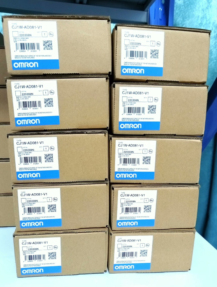

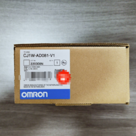
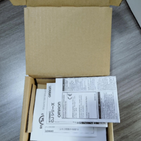
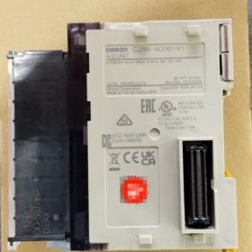
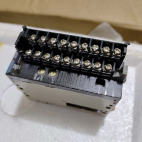
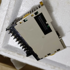
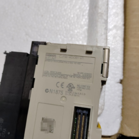
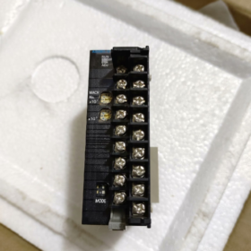
CJ1W-AD081-V1
- CJ1W: Special I/O module series base for CJ1-series PLCs
- ANNONCE: Entrée analogique
- 08: 8 canaux d'entrée analogiques
- 1: Standard hardware revision
- V1: Upgraded functional version (supports wire break detection, dual resolution switching, and digital smoothing filter)
Derivative Model: CJ1W-AD081-V1-SL (spring screwless terminal type)
- Spécifications matérielles de base
Paramètres de base
| Article | Spécification |
| Nombre de canaux | 8 independent analog inputs (CH1~CH8) |
| Processeurs API compatibles | Full lineup of CJ1M / CJ1H / CJ2M / CJ2H CPUs |
| Interface de bus | Dedicated CJ backplane I/O bus; aucune alimentation externe requise |
| Backplane Power Consumption | DC 5V ≤ 420mA |
| Isolation Scheme | Optocoupler isolation between internal module circuit and PLC bus; pas d'isolation entre les canaux individuels |
| Dimensions hors tout | W31mm × H90mm × D65mm |
| Poids | ≤ 140g |
| Environnement opérationnel | 0~55°C, 10%~90% RH non-condensing |
| Terminal Specifications | Modèle standard: Bornes à vis M3; SL model: spring quick-disconnect terminals, 18-pin detachable terminal block |
Input Signal Ranges (Hardware DIP switch selectable per channel)
Voltage Input (DIP Switch = OFF)
-10~+10V, 0~10V, 0~5V, 1~5V
Impédance d'entrée: ≥1 MΩ, Maximum Withstand Voltage: ±15V
Current Input (DIP Switch = ON, built-in 250Ω sampling resistor)
4~20mA, 0~20mA
Impédance d'entrée: 250Oh, Maximum Withstand Current: ±30mA
Conversion Accuracy & Résolution
- Two software-selectable resolution grades
4000-count (12-peu): Economical mode with fast conversion speed
8000-count (13-peu): High-precision mode for precise flow/pressure measurement
- Full-scale Accuracy (Température ambiante: 25°C)
Voltage Input: ±0,2% FS
Current Input: ±0.4% FS
- Full-temperature Range Accuracy (0~55°C)
Signal de tension: ±0.4% FS
Signal actuel: ±0.6% FS
- Vitesse de conversion: 1ms par canal; full scan of 8 channels takes 8ms; high-speed mode: 250μs par canal
- Fonctions de base intégrées
- Wire Break Detection (Dedicated for 4~20mA Circuits)
When a current loop is open, the corresponding channel wire break flag turns ON for program-based alarming.
- Digital Smoothing Filter
Average value calculation to suppress sensor jitter and on-site electromagnetic interference.
- Peak / Valley Hold
Captures and locks the maximum and minimum analog values within a cycle, suitable for impact pressure and instantaneous flow acquisition.
- Compenser / Gain d'étalonnage
Onboard calibration registers allow on-site correction of sensor zero drift.
- Custom Range Scaling
Upper and lower limits of ±32000 can be configured to directly map 4–20mA signals to engineering values such as 0~1000 or 0~5000.
- Définition du câblage des bornes (18-Pin Terminal Block)
Each channel occupies two terminals: V+ (Signal Positive), COM (Common Negative)
CH1: Broche1(V+), Broche2(COM)
CH2: Broche3(V+), Broche4(COM)
CH3: Pin5(V+), Pin6(COM)
CH4: Broche7(V+), Broche8(COM)
CH5: Pin9(V+), Pin10(COM)
CH6: Pin11(V+), Pin12(COM)
CH7: Pin13(V+), Pin14(COM)
CH8: Pin15(V+), Pin16(COM)
Pin17, Pin18: Shield grounding terminals (Connect all sensor shield cables here for anti-interference performance)
Directives de câblage
- Voltage signals: Connect only V+ and COM; set DIP switch to OFF
- 2-wire 4~20mA transmitters: Connect V+ to transmitter positive terminal, COM to 24V negative terminal; set DIP switch to ON
- It is recommended to common the COM terminals of multiple sensors. Connect shield layers to pins 17/18 of the module at one end only; double-end grounding is prohibited.
- PLC Memory Allocation (Special I/O Unit)
- Input Relay Area (10 Words): Stores raw A/D conversion values for 8 chaînes
CH1: Channel Word 0; CH2: Channel Word 1 … CH8: Channel Word 7
- Output Relay Area (10 Words): Function setting registers
Includes resolution switching, filter sampling count, wire break detection enable, upper/lower scaling limit parameters
- Logiciel de configuration: Programmeur CX + Intégrateur CX. Channel addresses are automatically assigned after registering the module in the I/O table.
- Scénarios d'application industrielle typiques
- Contrôle des fluides: Acquisition of 4–20mA transmitters for pressure, liquid level and flow
- Temperature Control Systems: 0~10 V / 1~5V temperature transmitter modules
- Analog Feedback for Inverters & Servomoteurs: Collection of 0~10V speed and torque feedback signals
- Centralized multi-point analog signal acquisition for water treatment, chemical and packaging machinery
- Comparaison de même série & Solutions de remplacement
Comparison of Analog Input Modules in the Same Series
| Modèle | Nombre de chaînes | Principales fonctionnalités |
| CJ1W-AD041-V1 | 4 chaînes | Low-cost solution for small-scale point acquisition |
| CJ1W-AD081-V1 | 8 chaînes | Standard general-purpose model with largest market stock |
| CJ1W-AD161 | 16 chaînes | High-density acquisition; without V1 enhanced functions |
Mise à niveau & Remplacements compatibles
- Direct drop-in replacement on the same platform: CJ1W-AD081-V1-SL (bornes à ressort, identical hardware parameters; aucune modification du programme requise)
- CJ2 Series Compatibility: Direct mounting on CJ2M/CJ2H CPUs with unchanged I/O configuration
- Replacement for legacy CS Series: CS1W-AD081-V1 (Backplanes are incompatible; CPU rack replacement is mandatory)
- New-generation NX Series Alternative (Recommandé pour les nouveaux projets): NX-AD4208 (8-entrée analogique de canal, Bus EtherCAT)
- Matrice de dépannage des pannes courantes
| Phénomène de défaut | Causes profondes | Étapes de résolution |
| All channels show fixed zero value | 1. Module not registered in CX-Integrator; 2. Mauvais contact du fond de panier; 3. Insufficient 5V backplane power supply | 1. Rebuild and download the I/O table; 2. Remove and re-seat the module firmly; 3. Reduce the number of modules installed on the backplane |
| Single channel value unchanged / stuck at full scale | 1. Incorrect DIP switch setting for voltage/current mode; 2. Open/short circuit in signal wiring; 3. Loss of 24V power supply to transmitter | 1. Verify channel DIP switch configuration; 2. Test circuit continuity with a multimeter; 3. Check power supply to sensors |
| Frequent wire break alarms on 4–20mA channels | 1. Excessive voltage drop along cables; 2. Insufficient load capacity of transmitters; 3. Loose terminal connections | 1. Use thicker signal cables; 2. Shorten cable length; 3. Serrer les vis des bornes |
| Severe signal drift and fluctuation | 1. Shield ground not connected; 2. Smoothing filter disabled; 3. Analog cables laid in parallel with power cables inside the same trunking | 1. Connect shield wires to module ground terminals; 2. Enable average filter in software; 3. Separate low-signal wiring and high-power wiring |
| Excessive conversion error | 1. Ambient temperature exceeds 55°C; 2. Long-term zero drift; 3. External signals out of rated range | 1. Improve cooling of control cabinet; 2. Perform offset/gain calibration; 3. Confirm matching of transmitter measuring range |
- Restrictions d'utilisation (Strictly Forbidden Operations)
- Do not set DIP switches of voltage-input channels to current mode; this will burn the internal sampling resistor of the module
- Never apply input signals exceeding ±15V (mode tension) or ±30mA (mode actuel); A/D chips may suffer permanent breakdown
- Avoid parallel routing of analog signal cables with power cables for inverters and contactors in the same cable trunking; severe electromagnetic interference will cause data distortion
- Double-end grounding of transmitter shield layers is prohibited, as circulating current will introduce power-frequency interference
- Power off the entire PLC system before plugging/unplugging modules; hot swapping will damage backplane bus interfaces
Official Accuracy Specifications of CJ1W-AD081-V1 (Per OMRON Manual Standards)
- Nominal Accuracy at Room Temperature (23±2°C / 25°C, Full-Scale Error)
- Voltage Input (0~5V / 0~10 V / -10~+10V / 1~5V)
Overall Accuracy: ±0,2% FS
- Current Input (4~20mA / 0~20mA)
Overall Accuracy: ±0.4% FS
> Note: FS = Full Scale, referring to relative error across the entire signal range, including integrated zero-point, gain and linearity errors.
- Full-Temperature Range Accuracy (0~55°C Operating Temperature)
Voltage Signals: ±0.4% FS
Current Signals: ±0.6% FS
- Résolution (Distinction Between “Précision” et “Résolution”)
Resolution refers to the minimum detectable signal change and is not equivalent to accuracy:
- Low-speed mode (1ms par canal): 1/4000 (12-peu)
- Mode haute vitesse (250μs par canal): 1/8000 (13-peu)
Error Calculation Examples
Calculation based on 4~20mA (full span = 16mA) with current accuracy ±0.4%FS:
Maximum Absolute Error = 16mA × 0.4% = ±0.064mA
Calculation based on 0~10V voltage with accuracy ±0.2%FS:
Maximum Absolute Error = 10V × 0.2% = ±0.02V
- Remarques supplémentaires
- Factory default calibration is optimized for voltage signals. For 4–20mA current loop applications, perform offset/gain calibration via software to further reduce current measurement errors.
- No galvanic isolation exists between channels. Additional measurement errors may be introduced by multi-sensor common-ground wiring, long cables or heavy electromagnetic interference; such errors are not included in the module’s nominal accuracy rating.
- The specified accuracy excludes external error sources such as sensor intrinsic error, cable voltage drop and grounding interference.
Full Application Scenarios of CJ1W-AD081-V1 (Classified by Industry, Equipment and Collected Signals)
This is a general-purpose 8-channel analog acquisition module compatible with 4~20mA / 0~10 V / 1~5V signals, equipped with wire break detection, digital filtering and peak hold functions. It supports CJ1H/CJ1M/CJ2M/CJ2H CPUs and is ideal for multi-point continuous physical quantity collection, closed-loop process control and equipment condition monitoring. No isolation between channels, making it suitable for sensor networks sharing a common ground at the same location.
- Chimique / Traitement de l'eau / Protection de l'environnement (Domaine d'application le plus courant)
Collected Signals
Mainly 4~20mA 2-wire transmitters: niveau de liquide, pression du pipeline, débit, PH/ORP, dissolved oxygen, turbidity, chemical reagent concentration, reactor temperature
Équipement & Systèmes
- Complete wastewater treatment equipment: Closed-loop dosing control based on biochemical tank liquid level, aeration pressure, influent and effluent flow rates, and chemical tank liquid level
- Pure water / reverse osmosis equipment: Collection of product water flow, pre/post-membrane differential pressure and conductivity transmitter signals
- Chemical reactors / mixing kettles: Interlocked temperature and pressure control based on kettle temperature, internal pressure and raw material feed flow
- Exhaust gas treatment / desulfurization & dénitrification: Monitoring of flue gas temperature, differential pressure, reagent flow and acid-base neutralization concentration
Avantages des modules
4~20mA wire break detection: Automatic alarm for broken cables or power loss of transmitters
Digital filtering eliminates power-frequency interference from water pumps and fans
8 channels enable simultaneous acquisition of multiple tank and pipeline measuring points to reduce total module quantity
- Nourriture & Boisson / Pharmaceutique / Ready Meal Production Lines
Collected Signals
Temperature transmitters (PT100 converted to 4~20mA), tank liquid level, syrup/material flow, filling pressure, vacuum degree
Équipement
- Sterilizing kettles, cooking pots: Closed-loop multi-point temperature control with interlock shutdown for overtemperature
- Batching and mixing systems: Automatic feeding based on raw material tank level and delivery flow ratio
- Filling and blow molding equipment: Collection of filling pressure and negative vacuum to guarantee filling precision
- Pharmaceutical purified water and mixing tanks: Compliant data logging of liquid level, temperature and differential pressure (GMP traceability)
Matching Strengths
±0.2% FS high precision at room temperature meets process metering requirements; peak hold captures instantaneous pressure fluctuations.
- Conditionnement / Impression / Caoutchouc & Plastics Machinery
Collected Signals
Predominantly 0~10V voltage signals: Servo/inverter speed feedback, tension sensors, mold cavity pressure, melt extrusion pressure
Équipement
- Verticale / machines d'emballage horizontales: Film roll tension and heat-seal temperature acquisition for constant-tension closed-loop control
- Moulage par injection / extrudeuses: Segmented barrel temperature, melt pressure and hydraulic system oil pressure
- Machines à imprimer: Roller pressing pressure and ink concentration transmitter signals
- Blow molding and bag-making equipment: Mold temperature and air supply pressure monitoring
Avantages correspondants
High-speed 250μs per channel conversion captures rapidly varying tension and pressure; centralized multi-channel acquisition of all analog feedback signals from the whole machine.
- CVC, Automatisation des bâtiments & Central Air Conditioning
Collected Signals
Température & humidity transmitters (4~20mA), air duct differential pressure, cold/hot water flow, chilled water pressure, CO₂ concentration
Systèmes
Factory central air conditioning, cleanroom air handlers, température constante & humidity units for dust-free workshops, fresh air & exhaust systems
Application Purpose
Automatically adjust fan speed and chilled water valve opening based on indoor temperature, humidity and CO₂ concentration for energy-saving coordinated control.
- Énergie, Photovoltaïque, Pompe à eau & Fan Stations
Collected Signals
Battery temperature, solar irradiance intensity, pump outlet pressure, water tank liquid level, motor bearing temperature
Scénarios
- PV energy storage cabinets: Multi-point temperature measurement of ambient environment and battery packs
- Constant-pressure water supply pump rooms: Closed-loop variable-frequency constant pressure control via pipeline pressure acquisition
- Air compressor stations: Monitoring and early warning of air tank pressure, exhaust temperature and lubricant oil temperature
- Boiler auxiliary equipment: Feed water flow, furnace negative pressure and flue gas exhaust temperature
- Machines-outils, Lignes de production automatisées & Custom Non-Standard Equipment
Collected Signals
Hydraulic oil pressure, cylinder pressure, cutting fluid temperature, 0~10V displacement sensors, vibration transmitters
Équipement
Tours CNC, chaînes de montage, stamping equipment, automated test fixtures
Fonctions principales
Equipment condition early warning with automatic shutdown for excessively low oil pressure or high temperature; dimensional inspection via displacement signal collection.
- Agriculture, Conservation de l'eau & Aquaculture
- Aquaculture: Automatic aeration and water exchange interlock based on water dissolved oxygen, water temperature and pond liquid level
- Irrigation & water conservancy: Automatic irrigation control via collection of pipeline flow, pool liquid level and soil humidity transmitter signals
Scénarios d'application non recommandés (Éviter les pièges de la sélection du modèle)
- Demand for strong isolation between multiple channels: Only the bus side features optocoupler isolation with no inter-channel isolation. For sites with multi-sensor separate grounding or severe interference, prioritize CJ1W-AD041-V2 (channel-isolated model).
- Control cabinets with high voltage and intense electromagnetic fields or dense inverters: External signal isolators must be installed to prevent severe signal drift.
- Moins que 4 analog measuring points: Select CJ1W-AD041-V1 for lower cost; choose CJ1W-AD161 for high-density 16-point acquisition.
Application Value Corresponding to Core Module Functions
- Wire Break Detection → Prevents circuit faults for 4–20mA transmitters in water treatment and chemical industries
- Digital Average Filter → Anti-interference for on-site water pumps, fans and inverters
- Peak / Valley Hold → Recording of injection melt pressure and instantaneous stamping pressure
- Compenser & Gain Calibration → Corrects long-term sensor zero drift to sustain consistent measurement accuracy
- 8-Channel Mixed Signal Compatibility → Supports mixed wiring of voltage and current transmitters on a single module to reduce cabinet module count





NH42-63-318x560.png "Commutateurs de transfert automatiques de type PC CHINT (ATS)NH42-63/4SZ")



