 Contacteur,disjoncteur,capteur,Encodeur,API,Convertisseur

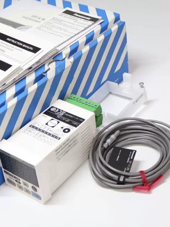

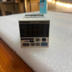
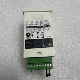
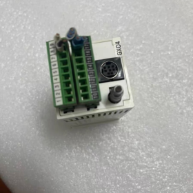
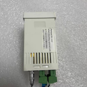
Présentation du produit: Haute précision à courants de Foucault série GP-X capteur de mesure de déplacement (type non laser). Ensemble complet = Contrôleur + Tête de capteur filetée M12 GP-X12ML
Distinction du modèle:
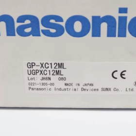
GP-XC12ML: Sortie NPN
GP-XC12ML-P: Sortie PNP (suffixe -P = PNP)
- Répartition du code modèle
| Segment de code | Définition |
| GP-X | Série de produits: Capteur de déplacement numérique à courants de Foucault |
| C | Contrôleur avec écran intégré (modèle complet intégré) |
| 12 | Tête de capteur filetée M12 |
| M. | Configuration de câble standard |
| L | Version longue portée; Plage de mesure: 0~5 mm |
| -P. | Pas de suffixe = NPN; avec -P = sortie collecteur ouvert PNP |
- Électricité de base & Spécifications de mesure
Paramètres de base
- Plage de mesure: 0~5mm (FS à grande échelle. = 5 mm)
- Matériau cible standard: Acier laminé à froid SPCC / Acier inoxydable SUS304 (60×60×1mm); seuls les métaux conducteurs peuvent être mesurés; plastiques, les verres ne sont pas détectables
- Linéarité: ±0,3 % FS.
- Résolution: 0.02%F.S.. (avec une moyenne de 64 fois activée) → 1 µm
- Taux d'échantillonnage: 25 µs (40 Réponse ultra-haute kHz, adapté à la rotation à grande vitesse & mesure des vibrations)
- Dérive de température: ≤0,07 % FS/℃; plage de travail optimale: 20~60 % de la pleine échelle
Paramètres électriques
Alimentation: 24 V CC ±10 %, ondulation crête à crête ≤ 10 %; Consommation électrique ≤150 mA
Sortie de commutation: Collectionneur ouvert, maximum. charger 100 mA, tension de tenue 30 VCC
Sortie analogique: 0~ Sortie de tension 5 V, impédance de sortie ≈100 Ω
Classe de protection: Tête de capteur IP67; résistant aux éclaboussures de liquide de coupe (les risques de corrosion dus aux produits pétroliers doivent être notés)
Température ambiante: -10℃ ~ +55℃
Câble: Câble coaxial standard (3 m); les rallonges d'origine sont prises en charge
Installation mécanique (Tête de capteur GP-X12ML)
Spécification du fil: M12×1
Dégagement minimum recommandé (pour éviter les interférences du métal environnant): ≥14 mm
Max.. couple de serrage: 20 N·m
⚠️ Ne pas trop serrer; une compression excessive endommagera les bobines internes et provoquera une défaillance permanente
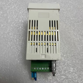
III. Définition du terminal du contrôleur (Unité principale GP-XC)
- 1: 24À DC (Puissance positive)
- 2: 0V (Puissance négative / GND)
- ANA: Sortie analogique (0–5V)
- SORTIE1: Sortie de comparaison 1
- SORTIE2: Sortie de comparaison 2
- TIMING: Entrée de déclenchement de synchronisation
- RÉINITIALISER: Réinitialiser l'entrée
- INT P: Maintenir l'entrée
COM: Borne commune pour les sorties
(Type NPN: COM se connecte à 0V; Type PNP: COM se connecte au 24V)
- Principe de fonctionnement
Un champ magnétique alternatif à haute fréquence induit des courants de Foucault sur une surface métallique. La variation de la distance entre la tête du capteur et la cible métallique modifie l'impédance des courants de Foucault., et le contrôleur convertit la variation d'impédance en valeur de déplacement.
✅ Avantages: Immunisé contre les brouillards d'huile, pulvérisation d'eau et poussière; aucune interférence de réflexion. Plus adapté aux environnements d'usinage difficiles par rapport aux capteurs de déplacement laser.
❌ Limites: Seuls les métaux conducteurs sont détectables; compensation matérielle & étalonnage requis pour l'aluminium, cuivre et acier; les non-métaux ne peuvent pas être mesurés.
- Scénarios d'application typiques
- Voile radial & détection de déviation des broches de machines-outils
- Inspection en ligne du diamètre intérieur du roulement et du faux-rond
- Surveillance du jeu des matrices d'emboutissage
- Mesure de vibrations et d'excentricité des rotors de moteurs
- Mesure d'épaisseur et de déformation pour les composants automobiles
- Surveillance dynamique du déplacement des pièces en rotation à grande vitesse
- Référence de sélection de modèle dans la série GP-X
| Modèle | Plage de mesure | Fil | Type de sortie |
| GP-XC10M | 0~2mm | M12 | NPN |
| GP-XC12ML | 0~5 mm | M12 | NPN |
| GP-XC12ML-P | 0~5 mm | M12 | PNP |
| GP-XC22KL | 0~10mm | M22 | NPN |
VII. Installation & Interdictions d'opération
- Évitez les collisions entre la surface de la tête du capteur et la pièce à usiner; Le contact direct du métal avec la face sensible est interdit
- Un espace libre suffisant autour de la tête du capteur est obligatoire; le métal à proximité ne provoquera aucune dérive
- Code d’identification de la tête du capteur d’entrée + 3-calibrage du point après remplacement de la tête du capteur. Une utilisation directe sans étalonnage entraîne une grave dégradation de la précision
- L'immersion à long terme dans un liquide de coupe fortement alcalin est interdite; L'indice IP67 protège uniquement contre les éclaboussures, non submersible
- Épaisseur du métal cible recommandée ≥0,8 mm; le métal ultra fin réduit la sensibilité
- Ne pliez pas brusquement ou ne pliez pas à plusieurs reprises le câble coaxial.; la rupture du fil haute fréquence interne entraîne une perte de signal
VIII. Dépannage des pannes courantes
- Forte fluctuation du signal: Interférence métallique environnante, câble endommagé, mauvaise mise à la terre
- Dérive zéro continue: Large fluctuation de la température ambiante (activer la compensation de température) ou montage de capteur lâche
- Tête de capteur méconnaissable: Connecteur coaxial lâche, Noyau de broche endommagé, contrôleur incompatible & tête de capteur
- Pas de signal de sortie analogique: Vérifier l'alimentation du contrôleur et la qualité des contacts des bornes
Si nécessaire, je peux fournir:
1) Schéma de câblage complet;
2) Procédure d'étalonnage en 3 points étape par étape pour le contrôleur;
3) Comparaison des paramètres entre le GP-XC12ML et les concurrents (Capteurs à courants de Foucault Keyence, Micro-Epsilon);
4) Extraits de la fiche technique PDF officielle.
Comparaison: Panasonic Capteur de courants de Foucault GP-XC12ML VS Keyence VS Micro-Epsilon
Résumé des spécifications de base
| Article | Panasonic GP-XC12ML | Keyence EX-V05 (Courants de Foucault M12) | Micro-Epsilon eddyNCDT 3010 (3010-Capteur M12) |
| Principe de mesure | Courants de Foucault haute fréquence | Courant de Foucault | Courant de Foucault |
| Plage de mesure | 0~5mm | 0~5mm | 0~5mm |
| Filetage de la tête du capteur | M12×1 | M12 | M12 |
| Linéarité | ±0,3 % F.S.. | ±0,3 % F.S.. | ±0,2 % F.S.. |
| Résolution | 1 µm (64-temps de moyenne) | 1 µm | 0.5 µm |
| Vitesse de réponse | 25 µs (40 kHz) | 50 µs (20 kHz) | Max.. 10 kHz (réglable) |
| Sortie analogique | 0~5V | 0~5V / 4~20 mA en option | 0~5V / 0~10V /4~20mA |
| Sortie de commutation | 2-canal NPN (-P pour PNP) | 2-canal NPN/PNP en option | Pas de sortie de commutation intégrée; jugement de seuil via le contrôleur hôte |
| Classe de protection du capteur | IP67 | IP67 | IP65 |
| Température de fonctionnement | -10℃~+55℃ | 0~+50℃ | -20℃ ~ + 80 ℃ |
| Type de câble | Câble coaxial haute fréquence dédié, ne peut être arbitrairement prolongé | Câble coaxial dédié | Câble coaxial, longueur étendue personnalisée disponible |
| Rémunération matérielle | Prend en charge l'étalonnage pour l'acier/SUS/Al/Cu | Compensation multi-matériaux | Base de données de matériaux étendue |
| Zéro & Gain d'étalonnage | 3-étalonnage des points | 2-étalonnage des points | Étalonnage multipoint |
| Niveau de prix | Qualité industrielle milieu de gamme | Qualité industrielle milieu de gamme | Qualité de précision importée haut de gamme (prix le plus élevé) |
Analyse des avantages
✅ Avantages du Panasonic GP-XC12ML
- Réponse la plus rapide à 40 kHz, supérieur pour la mesure du battement de rotation à grande vitesse et des vibrations à haute fréquence
- Equipé de deux sorties de comparaison matérielle, alarme de limite supérieure/inférieure directement disponible sans calcul PLC
- Écran intégré sur le contrôleur pour une mise en service sur site; aucun logiciel PC requis
- Performance stable sous huile de coupe & conditions de poussière; largement appliqué dans les équipements d'automatisation domestique
✅ Avantages du Keyence EX-V05
- Options de sortie flexibles, prise en charge native du signal analogique 4 ~ 20 mA
- Fonctionnement intuitif du menu, faible barrière de mise en service
- Stock adéquat à l’échelle mondiale avec un délai de livraison court
✅ Avantages du Micro-Epsilon eddyNCDT3010
- Linéarité et résolution supérieures, idéal pour les mesures de laboratoire et de qualité métrologique
- Large plage de températures de fonctionnement avec une dérive plus faible sous des températures extrêmes
- Prise en charge de câbles de signal plus longs, adapté à la mesure à distance de machines à grande échelle
⚠️ Inconvénients respectifs
- Panasonic GP-XC12ML
Pas de sortie analogique 4 ~ 20 mA; 0-5Signal de tension V sensible aux interférences sur une longue distance de transmission; performances de dérive en température inférieures à celles du Micro-Epsilon.
- Keyence EX-V05
Vitesse de réponse inférieure; risque de manquer des données de pointe pour la fréquence de vibration >1 kHz.
- Micro-Epsilon 3010
Aucune sortie de commutateur matériel; contrôleur de correspondance obligatoire; prix environ. double de Panasonic; Logiciel PC requis pour la configuration, peu pratique pour le débogage sur le terrain.
🎯 Conseils de sélection
- Donner la priorité au Panasonic GP-XC12ML
Faux-rond de broche de machine-outil, excentricité du moteur, inspection de pièces rotatives à grande vitesse, surveillance en ligne de l'estampage; scénarios nécessitant une sortie d'alarme matérielle, échantillonnage à grande vitesse et réglage pratique sur site.
- Donner la priorité au Keyence EX-V05
Surveillance du déplacement à basse vitesse, applications nécessitant un signal analogique standard 4-20 mA, exigence de délai de livraison court.
- Donner la priorité à Micro-Epsilon eddyNCDT
Mesure de précision en laboratoire, environnement à large fluctuation de température, précision au niveau métrologique, budget suffisant, aucune demande de sorties de commutation matérielles.
Rappel de compatibilité
Les câbles de signal des trois marques ne sont pas interchangeables. Une impédance coaxiale haute fréquence différente entraînera une dérive de mesure et un bruit excessif.
Les trois capteurs ne peuvent pas détecter les non-métaux; un étalonnage séparé est requis pour les tôles ultra fines (épaisseur <0,6 mm).
Manuel d'utilisation complet: 3-Calibrage linéaire ponctuel pour Panasonic GP-XC12ML
Modèle applicable: GP-XC12ML (Plage de mesure: 0~5mm) Capteur de courants de Foucault
⚠️ Conditions préalables obligatoires:
- 3-l'étalonnage du point doit être effectué après le remplacement du capteur, rallonge de câble ou changement de matériau cible;
- Préparer le bloc de test en métal avec un matériau identique à celui de la pièce à usiner, dimension minimale 60×60×1mm;
- Installation mécanique complète; assurez-vous qu'il n'y a aucune interférence métallique à proximité autour de la tête du capteur;
- Stabiliser la température ambiante; allumer et préchauffer pendant 15 minutes avant l'étalonnage.
- Paramètres de base du pré-étalonnage
- ID de la tête du capteur d’entrée
Entrez dans le menu HEAD ID après la mise sous tension, saisissez le code de série à 6 chiffres imprimé sur la tête du capteur GP-X12ML.
Un étalonnage sans ID correct entraînera une grave non-linéarité et une dérive de mesure.
- Sélectionnez le matériau cible
Menu TAPIS: Fe (Acier/SPCC), LEUR (Acier inoxydable), Al (Aluminium), Cu (Cuivre).
Un réétalonnage est nécessaire une fois que le matériau de mesure change.
- Configuration de la longueur du câble via le commutateur DIP à l'arrière du contrôleur
Câble standard de 3 m → réglé sur 3 m
Câble étendu (longueur totale ≤10m) → réglé sur 3m+7m, redémarrer pour activer le réglage.
- Définition de 3 Points d'étalonnage (Gamme GP-X12ML 0 ~ 5 mm)
| Point d'étalonnage | Écart physique (capteur face à une cible métallique) | Signification |
| Indiquer 0 (Point zéro) | 0 mm (bloc de test fermement fixé à la face du capteur) | Limite inférieure de la plage de mesure |
| Indiquer 1 (Point médian) | 2.5 mm (position médiane de la pleine échelle) | Point intermédiaire linéaire |
| Indiquer 2 (Pleine échelle) | 5 mm (distance de détection maximale) | Limite supérieure de la plage de mesure |
Un dispositif ajusté au micromètre est recommandé pour un positionnement précis. Attendez une lecture stable avant de confirmer.
III. Procédure de fonctionnement des boutons du panneau
Boutons du contrôleur: MODE / ▲ / ▼ / ORL (Confirmer)
- Sous écran de mesure normal, appuyez sur 【MODE】, La LED orange MODE s'allume pour accéder au menu de réglage.
- Faites défiler via ▲▼ pour sélectionner cALIb (Étalonnage), appuyez sur 【ENT】.
- L'écran affiche P0 → fixez fermement le bloc de test contre la face du capteur. (0 mm).
Attendez une lecture stable, appuyez sur 【ENT】pour enregistrer le point zéro.
- L'écran passe à P1 → ajustez l'écart à 2.5 mm milieu.
Après la lecture se stabilise, appuyez sur 【ENT】pour enregistrer le point médian.
- L'écran passe à P2 → ajustez l'écart à 5 mm pleine échelle.
Après la lecture se stabilise, appuyez sur 【ENT】pour enregistrer la valeur à pleine échelle.
- Après que trois points soient enregistrés, Le magasin apparaît; appuyez à nouveau sur 【ENT】 pour enregistrer définitivement les paramètres d'étalonnage.
- Appuyez sur MODE pour quitter le menu et revenir à l'affichage des mesures.
❗ Gestion des codes d'erreur
Err-Pos: Distance insuffisante entre les points d'étalonnage, position hors de portée ou bloc de test métallique sous-dimensionné; repositionner la cible.
Err-MAT: Le matériau sélectionné ne correspond pas au matériau du bloc de test; vérifier le paramètre MAT.
- Remise à zéro en un seul point (Décalage simple, PAS équivalent à l’étalonnage en 3 points)
Uniquement pour un réglage simple du décalage sans correction de linéarité:
Sous l'écran de mesure, appuyez longuement sur [MODE] 2 secondes, la valeur actuelle de l'écart sera mise à zéro.
Note: La réinitialisation en un seul point ne déplace que le décalage du zéro et ne peut pas corriger l'erreur non linéaire. Ne remplacez jamais l'étalonnage en 3 points par une réinitialisation en un seul point pour une inspection de haute précision.
- Fonction auxiliaire: Mise à l'échelle de la sortie analogique (0~5V correspondant à 0~5mm)
Mise à l'échelle analogique complète après avoir terminé l'étalonnage en 3 points:
- Appuyez sur MODE pour entrer dans le menu → sélectionnez ANA (Sortie analogique)
- Configurer les paramètres:
0mm écart → Sortie = 0 V
5mm écart → Sortie = 5 V
- INV en option: La tension de sortie diminue à mesure que l'écart augmente (activer selon les besoins).
- Suggestions avancées (Faux-rond de la broche & Mesure des vibrations)
- Paramètre de filtre de moyenne AVG: Valeur recommandée 16 ~ 64 fois. Évitez une moyenne excessive pour un échantillonnage à grande vitesse de 40 kHz afin d'éviter toute perte de signal de pointe..
- Réglage du seuil pour les sorties de comparaison OUT1/OUT2: Terminé après l'étalonnage. Configurer ultérieurement les limites d'alarme HI/LO.
- 4 banques de mémoire MEM1 ~ MEM4: Stocker les paramètres d'étalonnage indépendants pour l'acier, acier inoxydable, aluminium, etc.. Rappel direct lors du changement de pièce, un étalonnage répété n'est pas nécessaire.
VII. Cycle d'étalonnage & Rappels de conservation des données
- Les paramètres d'étalonnage sont conservés après la mise hors tension;
- Réétalonnage requis dans certaines conditions: fluctuation de la température ambiante >±15℃, changement de position du capteur causé par les vibrations, remplacement de la tête du capteur ou des câbles;
- Enregistrer les positions des luminaires après l'étalonnage pour une vérification répétée.



NH42-63-318x560.png "Commutateurs de transfert automatiques de type PC CHINT (ATS)NH42-63/4SZ")



