 Contacteur,disjoncteur,capteur,Encodeur,API,Convertisseur

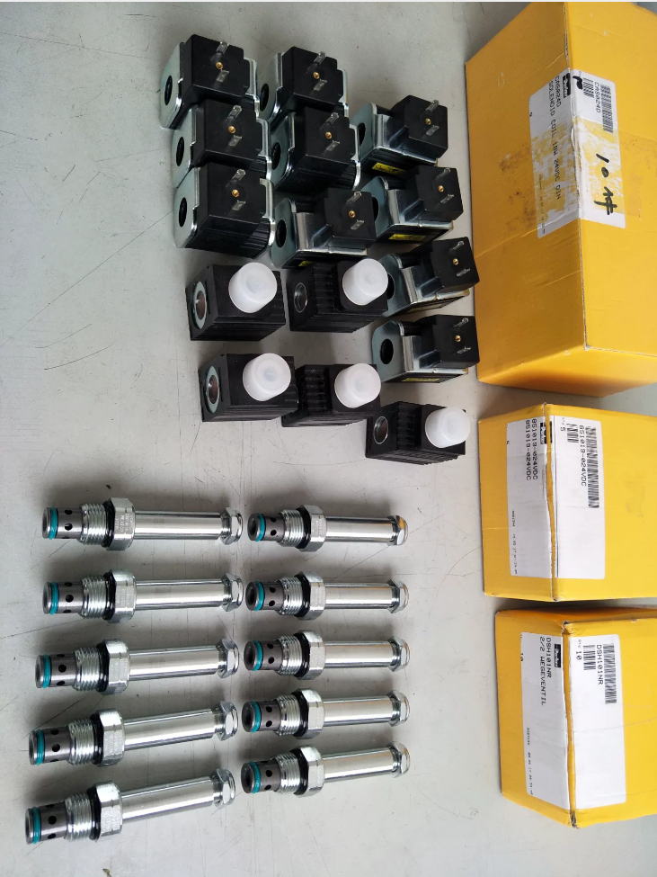

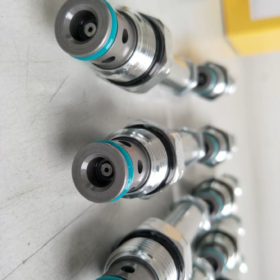
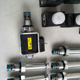
DSH101NR
DSH101: Series – 2-way poppet type solenoid cartridge valve, standard cavity C10-2
N = Normally Open: Open when de-energized, closed when energized
R = Reverse free flow
Fonction: Flow permitted 2→1 when open; closed upon energization; free reverse flow 1→2 (integral check function)
- Principales spécifications techniques
| Article | Paramètre |
| Type de vanne | 2-position 2-way poppet solenoid cartridge valve |
| Mounting Cavity | Standard C10-2 cavity |
| Max Operating Pressure | 350 bar (5000 psi) |
| Débit nominal | 60 L/min (15 GPM) |
| Closed Leakage | Environ. 0.33 cc/min (5 drops/min, 32cSt hydraulic oil) |
| Temps de réponse | Clôture (énergique): ≈70 ms; Ouverture (de-energized): ≈35 ms |
| Matériau du corps de vanne | All steel, moving components hardened |
| Médias compatibles | Huile minérale, synthetic hydraulic fluid; Viscosity range: 6~420 cSt |
| Filtration Requirement | OIN 4406 18/16/13 ou supérieur |
| Standard Seal | PU D-ring; Optional NBR, FKM |
| Température de fonctionnement | PU seal: -37℃~+93℃ |
| Couple d'installation | Cartridge: 69~75 N·m; Solenoid locking nut: 7~10 N·m |
| Poids | Environ. 0.2 kilos |
- Logique de fonctionnement
- Solenoid de-energized (normal state): Valve open → Port 2 ↔ Port 1 connected
- Solenoid energized: Solenoid actuates poppet to close → Flow 2→1 blocked; Free flow 1→2 remains available
Applications typiques: Single-acting cylinder pressure relief, load holding, lowering cut-off, accumulator unloading circuits
- Common Suffix Options (Exemples de modèles complets)
DSH101NR24: 24Bobine VCC (le plus courant)
DSH101NR12: 12Bobine VCC
DSH101NRMS: With manual override button
DSH101NRTN: Deutsch DT04 connector
DSH101NREVS: Deutsch EV series connector
- Quick Series Comparison (Guide de sélection)
DSH101C / CR: Normalement fermé (Caroline du Nord)
DSH101N / NR: Normalement ouvert (NON)
Suffix without R: Restricted reverse flow; Suffix R = Free reverse flow (NR/CR)
- Domestic Equivalent Reference
Interchangeable C10-2 cavity 2-way solenoid poppet valve with NO + free reverse flow:
HydraForce SV10-21, Vickers, TREMPER, Jialang equivalent cartridge valves.
À la demande, je peux fournir:
- Text dimension drawing for C10-2 manifold cavity
- Typical circuit drawing (single-acting cylinder lowering control)
- Excerpts from original manufacturer datasheet
Application Scenarios of Parker DSH101NR
Key function recap for selection reference
DSH101NR: Normalement ouvert + Reverse Free Flow
Hors tension: Passage 2→1 open; Énergisé: 2→1 blocked; permanent free flow 1→2 (built-in check valve feature)
Poppet construction provides low closed leakage; C10-2 mounting cavity, maximum 350 bar, rated flow 60 L/min.
- Mobile Hydraulics (Primary Application Field)
1.1 Single-Acting Cylinder Lifting & Load Lowering Circuit (Utilisation typique)
Outrigger cylinders & telescopic single-acting cylinders on aerial work platforms
Tipper truck, sanitation equipment lift cylinders
Material clamping & compression single-acting hydraulic cylinders for construction machinery
Circuit Operation Logic:
De-energized state: Cylinder cap side connected to tank, cylinder lowers under load weight
Energized state: Tank path blocked, cylinder locked for load holding
During lifting, pressure oil flows freely 1→2 (Suffix R free reverse flow supplies lifting flow, no separate check valve required)
✅ Avantage: Single valve realizes lowering on/off control + lifting check function, simplifies manifold circuit layout.
1.2 Accumulator Safety Unloading / Pressure Relief Circuit
Accumulator pressure holding systems:
Machine shutdown / emergency condition: Solenoid de-energized, accumulator pressure relieved via 2→1
Fonctionnement normal: Solenoid energized, accumulator circuit sealed to maintain pressure
System charging: Fluid flows freely 1→2 into accumulator
Largement utilisé: Mobile hydraulic clamps, hydraulic breaker accumulator circuits.
1.3 Brake Drain Control for Unidirectional Hydraulic Motors
Controls motor backpressure line for unidirectional rotary hydraulic motors:
Energized to block backpressure for braking; de-energized to open circuit and allow motor rotation; supply oil passes freely through 1→2.
- Industrial Hydraulic Power Units
2.1 Hydraulic Clamps & Press Equipment – Single-Acting Clamp Cylinders
Clamp extension: Pressure oil flows freely 1→2
Clamp retraction: Printemps / load weight retracts cylinder when valve de-energized to open tank line
Standby during production: Solenoid energized to block return line and maintain clamping force; low poppet leakage minimizes pressure decay.
2.2 Pressure Chamber Relief & Safety Dump Valve
Mold hydraulics, hydraulic test benches:
Energized to seal high-pressure chamber during operation; de-energized to automatically depressurize chamber after process completion or safety trigger.
2.3 Circuit Selector & Pump Bypass Unloading Circuit
Pump bypass unloading: Normalement ouvert (de-energized) for direct pump unloading; energized to cut unloading path and build system pressure.
- Conditions de travail inappropriées (Pièges de sélection)
- Bi-directional locking for double-acting cylinders ❌
Only blocks flow 2→1; path 1→2 is permanently open, cannot seal both directions. For bi-directional pressure holding, select DSH101CR or bi-directional poppet valves.
- Application requiring load holding after power loss, relief on energization ❌
DSH101NR: De-energized open, energized closed. If load must remain locked when power fails, select DSH101CR (Normalement fermé, free reverse flow).
- Continuous steady flow exceeding 60 L/min: Upgrade to DSH161 series.
- Function Comparison for Fast Selection
DSH101NR: Normalement ouvert, free reverse flow → De-energized relief, energized load holding (first choice for single-acting cylinder lowering)
DSH101CR: Normalement fermé, free reverse flow → De-energized load holding, energized relief (safety critical power-off holding applications)
Installation Guidelines for Parker DSH101NR (C10-2 Cavity)
- Inspection avant installation (Critique)
1.1 Verify Model & Fonction de la vanne
DSH101NR: Normalement ouvert + Reverse Free Flow
Définition du port: 2→1 controlled flow path; permanent free flow 1→2
⚠️ Reversed port connection will completely invalidate circuit function!
Manifold port marking must match valve flow direction.
1.2 Manifold Cavity Inspection
Standard cavity: SAE C10-2. Non-standard machining will cause seal leakage and valve sticking.
Thoroughly clean cavity: Remove metal chips, burrs and seal debris. Flush with high-pressure oil; do not insert cotton yarn into cavity (risk of fiber contamination and valve seizure).
Inspect sealing face for scratches; surface damage will cause external leakage of outer D-ring.
1.3 Seal Verification
Standard fitted PU polyurethane D-ring (no back-up ring required)
Huile minérale, normal temperature: Unité centrale (-37~93℃)
Haute température / synthetic fluid: Replace with NBR or FKM fluorocarbon seal
Never reuse removed seals. Lubricate lightly with clean hydraulic oil before installation. Do not use grease (risk of carbonization and valve sticking).
- Cartridge Installation Torque (OEM Standard)
Cartridge threaded torque into manifold: 69~75 N·m
✅ Torque wrench is mandatory!
Couple insuffisant: Outer D-ring incomplete sealing → external leakage
Excessive torque: Thread stripping, manifold cavity deformation, internal valve damage, sluggish operation and increased leakage.
Procédure d'installation:
- Ensure seal fully seated in cartridge groove without twist or extrusion
- Thread cartridge manually until seal contacts manifold face
- Tighten to specified torque with torque wrench
- Do NOT rotate cartridge by gripping solenoid housing; only clamp the hexagonal threaded section!
- Solenoid Coil Assembly Requirements
- Solenoid locking nut torque: 7~10 N·m
Over-tightening risks cracking solenoid housing.
- Assembly sequence:
Positioning washer on cartridge top → Slide coil over actuator pin → Secure with locking nut.
Ensure coil base fully seats flat on cartridge top without tilt or gap.
- Coil can be rotated 360° to adjust cable outlet orientation for convenient wiring.
- Models with manual override (MS suffix): Confirm manual button can be fully depressed without interference after assembly.
- Electrical Wiring Requirements
- Supply voltage must stay within 85%~110% of nominal rating. For 24VDC coil, avoid voltage below 20.4V. Undervoltage leads to unreliable valve closure and load slipping.
- Waterproof connector treatment: Adequate sealing required for mobile / outdoor equipment to prevent water ingress and coil short circuit. Fit O-rings correctly on Deutsch DT/EV connectors.
- Dissipation thermique: Coil temperature rises during frequent continuous cycling. Do not insulate coil; maintain ventilation space.
- EMI control: Route wiring away from inverters and high-power motors to avoid unintended valve actuation.
- Hydraulic System & Flushing Requirements
- System cleanliness level: OIN 4406 18/16/13. Install upstream filter. Contamination will score poppet sealing surface and cause permanent internal leakage.
- Flush manifold without cartridge installed!
Install DSH101NR only after flushing is complete, preventing weld slag entering valve internals.
- Initial commissioning: Run no-load at low speed and verify:
No external leakage at manifold interface
Acceptable pressure decay rate during load holding
Fast, consistent valve actuation on energization / de-energization without delay.
- Orientation de montage & Limites de fonctionnement
- No mandatory installation orientation: Horizontal or vertical mounting permitted.
For vertically downward loaded cylinders, avoid cartridge facing downwards long-term to prevent sediment accumulation.
- Fluid viscosity range: 6~420 cSt. Avoid excessive viscosity at low ambient temperature which slows response.
- Rated flow ≤60 L/min; limit pressure differential under sustained high flow to prevent excessive heat generation.
- Opérations interdites & Erreurs d'installation courantes
❌ Do not tighten by experience without torque wrench
❌ Do not rotate cartridge by clamping solenoid housing, causing eccentric actuator pin and seizure
❌ Do not mix different seal materials; no extra back-up rings needed for PU D-ring
❌ Do not apply thread sealant or PTFE tape on cartridge threads (sealant entering valve causes poppet seizure)
❌ Do not swap Port 1 and Port 2 (reversed flow destroys circuit function)
❌ Do not install valve before full system flushing (high risk of internal leakage and load drift)
- Commissioning Check List
- Test statique: De-energized = passage open; Energized = flow 2→1 blocked; permanent free flow 1→2
- Pressure holding test: Monitor pressure decay rate under energized lock condition to evaluate poppet internal leakage
- Inspect all sealing positions for external leakage
- Verify no abnormal overheating of solenoid after continuous energization





NH42-63-318x560.png "Commutateurs de transfert automatiques de type PC CHINT (ATS)NH42-63/4SZ")



