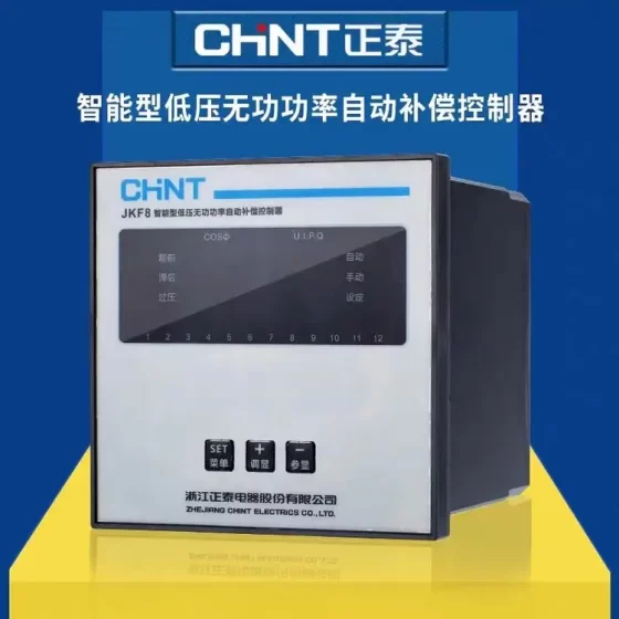
Contacteur,disjoncteur,capteur,Encodeur,API,Convertisseur





Nom complet du modèle: PSR-SPP24UC/ESA4/2X1/1X2
Série: PSRclassic relais de sécurité, Contact Phénix dual-channel safety monitoring module for emergency stop and safety gate monitoring
✅ Core Safety Ratings
EN ISO 13849: Cat.4 / PL e
CEI 61508 / DANS 62061: SIL 3
Stop Category: Catégorie 0 arrêt
✅ Electrical Specifications
Fournir: 24 À DC (-15% ~ +10%), typical power consumption 1.68 W, typical current 70 mA
Sortir: 2 safety normally open contacts + 1 signal feedback contact
Évaluation des contacts: 250 V CA/CC, continuous current 6 UN (AgSnO₂ gold-plated contacts)
Minimum switching load: 10 V, 100 mW
Durée de vie mécanique: environ. 10⁷ opérations
Temps de réponse: environ. 150 ms for automatic start; release time 20~45 ms
Recovery time: ≥1 s
✅ Wiring & Construction
Type de câblage: Push-in pluggable terminals
Section de fil: 0.2~1,5 mm² (AWG24~16), longueur de dénudage 8 mm
Montage: Montage sur rail DIN, yellow housing RAL1018, PA material
Dimensions: W22.5 mm × H112 mm × D114.5 mm
Classe de protection: IP20 (module body)
✅ Functions & Start Mode
Dual-channel monitoring: boutons d'arrêt d'urgence, safety gate switches
Start mode: automatic start (ESA4 version, no external reset)
Built-in status LED indicators
Input circuit supports two-wire safety circuit detection for wire breakage and short-circuit faults
✅ Environmental Conditions
Température de fonctionnement: -20℃ ~ +55℃
Storage/transport temperature: -40℃ ~ +70℃
Vibration: 10~150 Hz, 2 g; choc 15 g
Maximum altitude: 2000 m
✅ Sélection & Référence alternative
Comparable models in the same series:
2963941: Manual reset version (ESA2)
2963925: Single-channel simplified version
Note: ESA4 = automatic start; ESA2 = external reset required. Not directly interchangeable.
✅ Applications typiques
Machines-outils, lignes de production automatisées, conveying equipment, robot peripheral safety circuits, dual-channel emergency stop / surveillance des barrières de sécurité, meets PL e and SIL3 safety requirements for machinery.
Troubleshooting Checklist for PSR-SPP-24UC/ESA4/2X1/1X2 (Order No.2963938) – Field Version
(je) Phénomène de défaut + État du voyant + Étapes de dépannage
1) Power LED off after power-up (no module response)
Possible causes: Pas de tension d'alimentation, sous-tension, polarité inversée, bornes desserrées, internal burnout
Troubleshooting steps:
- Measure voltage at A1/A2: must be 24 VCC (20.4~26.4 V), AC220V is strictly prohibited
- Check whether wires are securely clamped in push-in terminals, longueur de dénudage 8 mm, no poor contact
- Confirm polarity is not reversed (A1=+24V, A2=0V)
- Cycle d'alimentation; if LED still off → internal module failure, remplacer directement
2) Power LED on, but safety output contacts do not close (no main output)
Case A: Fault in input circuit (dual-channel emergency stop / barrière de sécurité)
- Confirm first: this model is ESA4 automatic start, no external reset terminal, reset button is not required
- Measure two input channels (S11/S12, S21/S22): both channels must conduct simultaneously
- Défauts courants:
Broken wire on one channel, poor contact of normally open contacts
Short circuit between two signal wires (short-circuit in two-wire circuit triggers fault lockout)
Oxidized or mechanically jammed contacts of safety gate switch
- Short-circuit test: temporarily short S11-S12 and S21-S22. If relay pulls in → external wiring / switch damaged; still no pull-in → module fault
Case B: Fault lockout triggered by circuit detection (internal latch)
Phénomène: Input signal appears normal, but relay stays open, still inactive after power cycle
Causes: Mismatched timing of two channels, court-circuit / wire breakage stored in fault memory
Handling: Power off for ≥1 minute then re-power; remains locked → replace module
3) Relay pulls in and opens immediately after release (momentary action)
Causes: Poor contact of input circuit, câblage lâche, contact bounce of button
Dépannage: Measure voltage drop section by section to eliminate loose terminals; use shielded cable to reduce interference
4) Output contacts close, but load does not operate
- Mesure 13/14 et 23/24 two sets of safety NO contacts: conduction resistance should be <0.5 Ω
- Forte érosion de contact (haute résistance) → contact failure, replace module
- Load-side short-circuit triggers safety disconnection, check external contactors and solenoid valves for short circuits
5) Random tripping and frequent false triggering (interference fault)
- Route power cables and safety signal cables separately, minimum distance ≥30 cm
- Add varistors on safety circuit to suppress surge voltage
- Confirm supply is an isolated DC power supply without ground noise
(II) Quick Self-Check Procedure (follow sequence)
- Measure power A1/A2: 24VDC normal ✅
- Measure two input channels: both conducting ✅
- Éteindre pendant 1 minute and re-power to clear fault lockout ✅
- Short input terminals to verify relay pull-in ✅
- Check continuity of output contacts ✅
- Eliminate open circuit, short circuit and interference on external wiring ✅
(III) Opérations interdites (to avoid invalidating safety rating)
Do not modify ESA4 automatic start model for external reset, this will invalidate PL e / Cat.4 rating
Do not parallel the two input channels; dual channels must be wired independently
Do not connect freewheeling diodes across safety contacts (reduces contact service life)
- Full Model List of PSR-SPP-24UC Series (Numéro de commande. + Modèle + Start Mode + Configuration des contacts)
(1) Dual-channel master modules for emergency stop / barrière de sécurité (ESA series, Cat.4 / PL e / SIL3)
- 2963938 | PSR-SPP-24UC/ESA4/2X1/1X2 | Automatic start (ESA4) | 2 safety NO + 1 feedback
- 2963941 | PSR-SPP-24UC/ESA2/2X1/1X2 | External manual reset (ESA2) | 2 safety NO + 1 feedback
- 2963954 | PSR-SPP-24UC/ESA2/4X1/1X2/B | Réinitialisation manuelle | 4 safety NO + 1 feedback (B pluggable terminal version)
- 2963996 | PSR-SPP-24UC/ESAM4/8X1/1X2 | Automatic start | 8 sécurité contact NO (high-output version)
(2) Single-channel simplified version (Cat.1~3 lower safety level)
- 2963925 | PSR-SPP-24UC/ESA4/1X1/1X2 | Single-channel automatic start
(3) Contact expansion modules (URM, used with master module for output expansion)
- 2964005 | PSR-SPP-24UC/URM4/5X1/2X2 | 5 NON + 1 NC expansion contacts
- 2981046 | PSR-SPP-24UC/URM4/5X1/2X2/B | B pluggable terminal version
(4) Règle de dénomination du modèle
PSR-SPP-24UC / ESA4 / 2X1 / 1X2
24UC: 24V AC/DC universal (this series only supports DC24V in practical use)
ESA4 = automatic start; ESA2 = external reset; ESAM = high-output multi-contact
2X1: 2 safety normally open contacts; 1X2: 1 feedback contact
III. Supplementary Interchange Notes
- 2963938 (ESA4 automatic) ≠ 2963941 (ESA2 manual reset). Wiring and PLC logic cannot be directly reused. Model replacement is mandatory to change reset mode.
- Suffix /B = separable pluggable terminals; no /B = fixed terminals. Electrical performance identical, seule la structure du terminal diffère.
Working Principle of Phoenix Contact PSR Dual-Channel Safety Relay (2963938, PL e / Cat.4 / SIL3)
Core summary: Two independent internal monitoring circuits check safety input signals continuously, while self-testing internal faults. It prevents safety loss caused by single-point failure. Once dangerous signal, rupture de fil, short circuit or internal fault is detected, safety outputs are reliably de-energized.
A standard relay only has one coil and one contact set. Single-point failure may cause contact welding and loss of protection, which is the problem safety relays are designed to solve.
- Dual-Channel Input Principle (Core for E-Stop & Safety Gates)
For model 2963938: Canal 1 S11-S12, Canal 2 S21-S22. Two independent circuits connect to one dual-contact emergency stop or safety gate switch.
✅ État normal: Both channels conduct simultaneously → module confirms safe condition, safety outputs close
❌ Safety trigger (E-Stop pressed, safety gate opened): Both channels open at the same time → safety outputs cut off immediately
⚠️ Fault detection:
One channel open, one channel closed → identified as wire breakage or single contact failure → fault lockout, outputs open
Short circuit between the two channels → module detects short-circuit fault and latches off
Design goal: Avoid false safe status caused by broken wire or welded contact. This is the foundation of Cat.4: safety function remains available after a single fault.
Distinction: ESA4 (2963938 automatic start): outputs restore automatically once both channels return to conducting state; ESA2 requires an external reset button for confirmation.
- Internal Dual-Channel Self-Test & Cross Monitoring (Key Difference from Standard Relays)
A safety relay is not simply a pair of ordinary relays. It contains two independent drive circuits plus two safety contact banks monitoring each other:
- Contacts of the two internal relays are connected in series inside the safety output path (sorties 13/14, 23/24)
- The module continuously compares the status of both internal relays:
If one internal relay contact welds closed, the other channel detects inconsistent status and locks the module, preventing output reclosure
Power-on self-test runs at startup to check coil and contact welding faults
👉 A standard relay with welded contacts keeps load powered. Safety relays detect this fault and lock out, preventing dangerous unintended startup.
- Feedback Contact (1X2, auxiliary contact for 2963938)
This auxiliary contact is not used for safety disconnection, only for status feedback to PLC or indicators:
It operates synchronously when safety outputs close
PLC uses it to judge safety circuit readiness and E-stop reset status
Important: Do not use this auxiliary contact for safety stop! Safety shutdown must use the two main safety contacts.
- Fault Latch Logic
The module enters fault lockout when any of the following occurs:
Mismatched dual-channel signals
Short circuit or wire breakage on input wiring
Internal relay contact welding fault
Timing anomaly caused by electromagnetic interference
Once locked, outputs will not restore automatically even after external wiring is repaired (ESA4 also requires sufficient power-off time to reset; ESA2 needs reset button actuation).
Design philosophy: Faults must be visible to personnel instead of silent recovery, eliminating hidden hazards.
- Catégorie 0 Arrêt (Ce modèle 2963938 is Category 0)
Safety relay outputs directly cut off the coil circuit of contactors, which is Category 0 arrêt: immediate power removal, coast-to-stop
Comparaison:
Cat.0: Direct power cut (ce modèle)
Cat.1: Controlled deceleration stop with delayed power removal (high-end safety controllers)
- Safety Rating Mapping
Cat.4: Dual-channel + self-test + fault lockout, single fault will not disable safety function; multiple faults are detected as much as possible
PL e: ISO13849, extremely low probability of dangerous failure, suitable for robots, machines-outils, presses and high-risk machinery
SIL3: IEC61508 functional safety, applied to high-risk process equipment
- Simple Analogy
Standard relay: Actuate when signal received, no self-check. Welded contact keeps load energized.
Safety relay:
Two eyes (dual input channels), two hands (two safety contact sets). The two eyes watch the two hands mutually.
If one eye loses signal or one hand sticks closed, it releases power immediately and locks itself to prevent dangerous startup.
Idées fausses courantes
- ❌ Two ordinary relays wired together do not equal a safety relay: standard relays lack cross-monitoring and short/open circuit detection, cannot achieve PL e
- ❌ Dual-channel does not mean simple parallel wiring: channels must be independent. Shorting S12 and S22 disables dual-channel fault detection


NH42-63-318x560.png "Commutateurs de transfert automatiques de type PC CHINT (ATS)NH42-63/4SZ")