 Contacteur,disjoncteur,capteur,Encodeur,API,Convertisseur

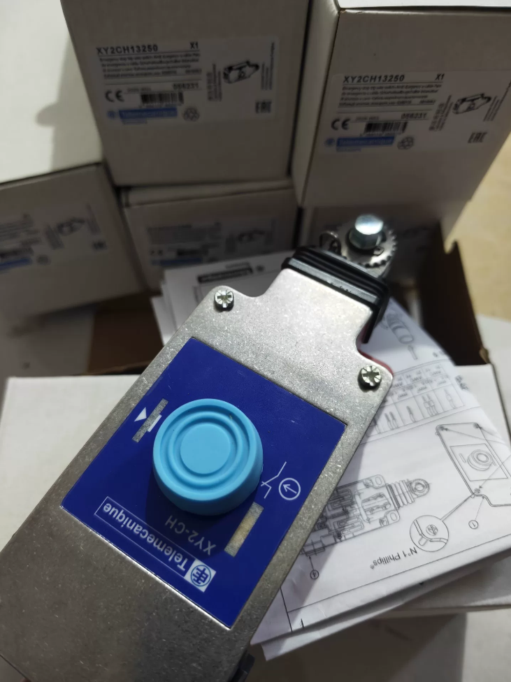

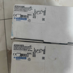
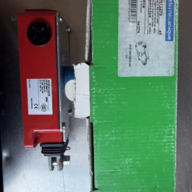
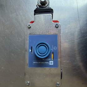
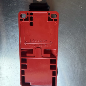
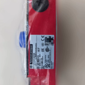
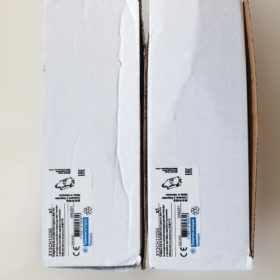
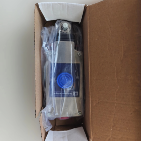
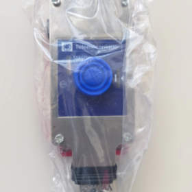
Explication du modèle: XY2CH series, booted push-button reset, 1NC+1NO, without indicator lamp; XY2CH13250H29 = cable entry thread changed to M20; standard version is Pg13.5.
Comparison with XY2CH13290: 13250 features only one safety NC contact; 13290 adopts dual-channel safety with two NC contacts — this is the core difference.
Spécifications de base
| Article | Paramètre |
| Configuration des contacts | 1Caroline du Nord (sécurité) +1NON (signal), slow‑break positive‑opening contacts |
| Mode de réinitialisation | Dust‑protected manual booted push‑button reset; latches after actuation, no auto‑reset |
| Max.. Rope Length | 30 m |
| Classe de protection | IP65 |
| Matériau du boîtier | Zamak die‑cast zinc‑alloy body, stainless‑steel cover |
| Cable Entries | 3 × Pg13.5; H29 suffix variant: 3 × M20 |
| Couple de serrage des bornes | 0.8‑1.2 N·m, conductor size 0.5‑1.5 mm² |
| Endurance mécanique | 800 000 operations; B10d = 4 000 000 |
| Température de fonctionnement | ‑25 ℃ ~ +70 ℃ |
| Safety Note (single‑channel hardware) | To achieve PL e / Cat.4 / SIL3, safety‑relay contact‑short‑circuit monitoring is mandatory. Direct single‑contact wiring max. achieves PL c only. |
Affectation des terminaux
| Numéro de borne. | Contact | Statut (non‑actuated) | After rope‑pull actuation |
| 21-22 | NC Safety Normally‑Closed | Fermé | Ouvrir (ouverture positive) |
| 13-14 | NO Signal Normally‑Open | Ouvrir | Fermé |
⚠️ Critique: Only one safety NC contact; no second hardware safety channel.
État normal: 21-22 fermé, 13-14 ouvrir. Pulling the rope triggers mechanical latching: 21-22 ouvre, 13-14 ferme. Restore by pressing the blue reset push-button.
Schémas de câblage
Scheme 1: High-Safety Level (PL e requires safety-relay monitoring)
- Fil 21-22 (Caroline du Nord) to one input channel of safety relay.
- Fil 13-14 (NON) to PLC DI for alarm feedback signal.
Since the hardware provides only one NC channel, Catégorie4 / PL e can only be achieved when the safety relay implements contact short-circuit monitoring. Without monitoring, max achievable safety level is PL c.
❗Do NOT externally parallel contacts; hardware only supplies one safety contact.
Scheme 2: Low-risk general-purpose equipment (PL e not satisfied)
Fil 21-22 in series into equipment emergency-stop circuit; 13-14 for alarm feedback.
Suitable for light-duty general-purpose conveyors. Strictly prohibited for high-risk conveyor systems.
Précautions de câblage
- Use only one cable entry; fit sealing plugs on the remaining two unused entries, otherwise IP65 protection is lost.
- Connect metal housing reliably to PE protective earth.
- Tighten terminals strictly to 0.8-1.2 N·m to avoid loose connections.
Installation mécanique
Mechanical installation requirements are identical to XY2CH13290. Refer to the full installation manual below:
- Max rope span 30 m; use φ3-5 mm plastic-coated steel wire rope.
- End-position tension spring is mandatory. Rope breakage shall also trigger emergency stop.
- First deflection pulley shall be mounted 100 mm away from switch body. Install rope clamps/support points every 5 m.
- Mount onto rigid metal brackets only; allow slight rope sag — do not over-tension nor allow excessive slack.
Pre-power-on Commissioning (de-energised, multimeter test)
- Reset completed: 21-22 fermé, 13-14 ouvrir.
- Pull rope to trigger latching: 21-22 ouvrir, 13-14 fermé.
- Press reset push-button to restore contact states.
- Test actuation at multiple positions all along the rope path to confirm reliable triggering even at far-end positions.
Comparaison des modèles: XY2CH13250 vs XY2CH13290
| Modèle | Configuration des contacts | Safety Channel | Application typique |
| XY2CH13250 | 1NC+1NO | Single‑channel | Low‑risk equipment, cost‑optimised; safety‑relay monitoring required for high‑level safety |
| XY2CH13290 | 2NC+1NO | Dual‑channel on‑board | Convoyeurs à bande, high‑risk material‑handling lines; industry‑preferred variant for direct dual‑channel safety‑relay input |
Selection Reminder: Prefer 13290 for belt conveyors and heavy-duty lines; 13250 is acceptable for light-duty general-purpose machines.
Equivalent Replacement Models
- Original Schneider variante: XY2CH13250H29 (M20 thread version)
- Alternatives nationales:
ELCO SR1-SN (1NC+1NO)
Schmersal ZQ700-11
Dépannage courant
- Unintended nuisance tripping: Excessive rope tension, bracket vibration. Reduce tension via turnbuckle; reinforce mounting structure.
- No actuation from far-end pull: Insufficient rope tension, seized deflection pulleys. Adjust tension; service pulleys.
- Cannot reset after tripping: Persistent tensile load remains on rope. Release rope residual tension before pressing reset button.
Type de produit: Latching emergency-stop rope-pull safety switch. Pulling the steel wire rope triggers emergency stop with mechanical latching; manual reset is mandatory. Applied to long-run conveyors, chaînes de montage, machines d'emballage, belt conveyors and other machinery safety protection.
General Core Specifications
| Article | Paramètre |
| Classe de protection | IP65 |
| Max.. Rope Length | 30 m |
| Endurance mécanique | 800 000 operations |
| Matériau du corps | Zamak die‑cast zinc alloy, stainless‑steel cover |
| Cable Entries | 3 × Pg13.5 (M20 for certain variants), bornes à vis |
| Couple aux bornes | 0.8‑1.2 N·m |
| Cote de sécurité | PL e / Cat.4 / SIL3 (requires compatible safety relay and correct wiring) |
| Contact Characteristics | Slow‑break, positive‑opening safety contacts |
| Housing Colour | Red RAL 3000 |
Model Naming & Main XY2CH Variants
XY2CH + numeric suffix. Suffix defines contact configuration, reset type, pilot-lamp option and thread specification.
- Reset Types
131xx: Flat push-button reset
132xx: Booted dust-protected push-button reset (most common industrial type)
134xx: Key-operated reset
- Configuration des contacts
XY2CH13250: 1NC+1NO, booted push-button reset
XY2CH13270: 2Caroline du Nord, dual safety normally-closed contacts
XY2CH13290: 2NC+1NO (le plus populaire; 2 safety NC + 1 signal NO)
XY2CH13450: 1NC+1NO, key-reset
XY2CH13293: 2NC+1NO, with 24 V pilot lamp
Suffix H29 = cable-entry thread changed to M20; default = Pg13.5.
Principe de fonctionnement
- Pull steel wire rope → internal mechanism latches mechanically; safety NC contacts positive-open.
- Machine shuts down; no automatic reset.
- After fault clearance, reset via push-button / clé; contacts restore for machine restart permission.
⚠️ Remarque: Rope-run ends must be fitted with tension springs, rope clamps and deflection pulleys. Avoid over-tightening or excessive slack. Rope-clamp spacing ≤ 5 m recommended.
Applications typiques
Convoyeurs à bande, lignes de production, lignes de conditionnement, systèmes de tri, long workstations, mining conveying equipment. Operators can trigger emergency stop by pulling the rope anywhere along the protected span.
XY2C Family Series Differentiation
XY2CH: Zamak zinc-alloy body, stainless-steel cover, max 30 m rope length, IP65, high mechanical endurance.
XY2CE: Boîtier en plastique, economy-grade, max 2 × 50 m bidirectional rope pull.
XY2CJ: Higher-grade IP66/IP67 protection for heavy-dust and wash-down environments.
Domestic-brand Reference Replacements
ELCO: SR-series rope-pull E-stop switches
Omron: D4A-N rope-pull switches
Contrinex / Schmersal: ZQ-series rope-pull safety switches
General Fault-Finding
- Frequent nuisance tripping: Excessive rope tension, seized pulleys, deformed mounting brackets.
- Échec de la réinitialisation: Mechanism jammed; residual rope tension not released.
- Open-circuit safety loop: Bornes lâches; verify tightening torque 0.8-1.2 N·m.
Schneider XY2CH13290 (Telemecanique Rope-Pull Emergency-Stop Switch)
Contacts: 2NC+1NO, booted push-button reset, no pilot lamp; max rope length 30 m; IP65; Pg13.5 cable entries. Suffix H29 = M20 thread.
- Affectation des terminaux
| Numéro de borne. | Contact Property | But |
| 21-22 | NC#1 (Safety Normally‑Closed 1) | Safety‑loop channel 1, positive‑opening |
| 31‑32 | NC#2 (Safety Normally‑Closed 2) | Safety‑loop channel 2, positive‑opening |
| 13-14 | NON (Normalement ouvert) | PLC alarm / status feedback signal |
Non-actuated state: 21-22 fermé, 31-32 fermé, 13-14 ouvrir.
Rope-pull latching: 21-22 et 31-32 open simultaneously; 13-14 ferme. Reset only via blue local push-button.
- Schémas de câblage
Scheme A: Safety-relay connection (achieve PL e / Cat.4 / SIL3 — Recommended)
- Feed independent dual NC channels 21-22 et 31-32 separately into dual-channel safety-relay inputs. Never externally short-circuit the two NC contacts — this invalidates safety rating.
- Fil 13-14 NO contact to PLC digital input for rope-pull-triggered alarm.
- Couple de serrage des bornes: 0.8-1.2 N·m. Conducteur: 0.34-1 mm² single-wire / max 0.75 mm² for two-wire parallel.
- Cable glands: 3 × Pg13.5; use one only; seal remaining two with blanking plugs to preserve IP65.
Scheme B: Simplified stand-alone wiring (PL e not satisfied, for basic stop-function only)
Wire both NC contacts in series into emergency-stop circuit; NO for alarm output. Cannot reach Category 4; only for low-hazard machinery.
⚠️Important: This is a mechanically latched device. It will NOT auto-reset after rope-pull actuation; manual push-button reset is required.
- Mechanical Installation Key-Points
- Steel wire rope: φ3-5 mm plastic-coated; max total length 30 m; fit tension springs at both ends.
- Rope clamps: install every ≤ 5 m; add deflection pulleys to prevent rope-to-housing friction.
- Rope tension: avoid over-tightening (nuisance tripping) and excessive slack; permit minor sag.
- Support de montage: rigid metal construction; no flexible supports. Switch can accept rope entry from left or right side.
- Température ambiante: −25 ℃ ~ +70 ℃.
- Dimensions hors tout (mm)
Corps: W 68 × H 95 × D 201 (including reset button and rope-pull lever mechanism)
Trous de montage: two M8 mounting holes on both sides.
- Original Schneider Equivalent-variant Selection Table
| Modèle | Contacts | Réinitialiser | Cable‑entry Thread | Remarques |
| XY2CH13270 | 2Caroline du Nord | Booted push‑button | Pg13.5 | Pure dual‑safety‑channel, no NO signal contact |
| XY2CH13250 | 1NC+1NO | Booted push‑button | Pg13.5 | Single safety channel |
| XY2CH13293 | 2NC+1NO | Booted push‑button | Pg13.5 | With 24 V pilot lamp |
| XY2CH13490 | 2NC+1NO | Key‑reset | Pg13.5 | Key‑unlock required for reset |
| XY2CH13290H29 | 2NC+1NO | Booted push‑button | M20 | Thread changed to M20 |
- Pin-to-pin Compatible Domestic Replacements
- Schmersal ZQ 900-22 (2NC+1NO, réinitialisation par bouton-poussoir)
- ELCO SR2-SN (2NC+1NO)
- Contrinex SN21-RPL-30M
Replacement reminder: Vérifier la configuration des contacts, reset type, max rope length and protection rating.
- Dépannage
- Frequent nuisance tripping: Excessive rope tension, seized pulleys, deformed brackets, heavy machine vibration. Reduce rope tension; inspect deflection pulleys.
- Cannot reset after tripping: Residual rope tension keeps mechanism locked. Release rope tension before pressing reset button.
- Intermittent open safety circuit: Under-torqued terminals. Retighten terminals to 0.8-1.2 N·m; re-crimp conductors.
- Water ingress damage: Unused cable entries not sealed with blanking plugs.
Complete Installation Operating Guide for Schneider XY2CH-Series Rope-Pull Emergency-Stop Switches
Modèles applicables: XY2CH13290, XY2CH13270, XY2CH13250 etc. Complies with EN/ISO 13850, IEC 60947-5-5, Machinery-Safety Directives.
⚠️ Condition préalable de sécurité: Perform all installation, wiring and commissioning with equipment de-energised under Lock-Out-Tag-Out (CŒUR). This is a tension-type rope-pull switch; proper pre-tension is required. Rope breakage shall also trigger emergency-stop protection.
- Préparation avant l'installation
1.1 Outils & Accessories List
| Catégorie | Contenu |
| Outils | M8/M6 spanner, cross‑head screwdriver, tournevis dynamométrique, multimètre, wire cutters |
| Accessoires obligatoires | φ3‑5 mm plastic‑coated steel wire rope, rope clamps, deflection pulleys, end‑position tension spring (obligatoire), turnbuckle, rigid metal mounting brackets, sealing blanking plugs |
| Electrical Cables | 0.34‑1 mm² control cables; terminal torque 0.8‑1.2 N·m; PE protective‑earth conductor for metal housing |
1.2 Environmental Verification
- Température de fonctionnement: −25 ℃ ~ +70 ℃; Indice IP65. Avoid heavily corrosive and high-impact locations.
- Max effective rope-protected length 30 m. Install an additional rope-pull switch if span exceeds this limit.
- Operating rope height above ground: 0.6-1.1 m, easily reachable by personnel; no obstacles obstructing the rope path.
- All mounting brackets must be rigid metal. Thin-sheet / flexible supports are forbidden; vibration will cause false triggering.
- Mechanical-body Mounting Procedure
- Secure the switch body
Fasten with M8 bolts through the two side mounting holes onto rigid machine frame; tightening torque 4 N·m. Align switch rope-exit direction with rope routing; do not twist the rope-pull lever mechanism.
Maintain 100 mm distance between switch body and first deflection-support point. Larger distance causes insufficient actuation stroke.
- Fit deflection pulleys
Fit deflection pulleys wherever the rope changes direction. Total deflection-angle sum ≤ 180°. Sharp bends and hard kinks are prohibited.
Install support / rope-clamp assemblies every 5 m along straight runs to limit rope sag.
Pulleys shall rotate freely without binding. Rope must not rub against machine frames or enclosures.
- Steel-wire-rope & end-spring assembly (étape critique)
1) Attach one rope end to the XY2CH rope-pull eyelet.
2) Thread rope through all deflection pulleys.
3) Fit end-position tension spring at the far rope end. Anchor the spring’s opposite end to rigid machine frame. Omission of this spring is a major safety hazard — pulling towards the switch will fail to trigger E-stop.
4) Secure rope with at least two rope clamps. Do not clamp over the sheath-stripping transition zone.
5) Adjust total rope tension via turnbuckle: keep rope moderately taut with minor sag. Do not over-tighten; do not allow excessive slack.
Over-tension: vibration-induced nuisance tripping. Under-tension: no reliable actuation from far-end positions.
- Mechanical acceptance check
Rope free of twist, kinks and abrasion. Avoid large-area sheath stripping to prevent corrosion.
Full-rope-travel movement is smooth without binding.
Vérifier: rope breakage will cause spring retraction and trigger emergency-stop.
- Electrical Wiring Procedure
XY2CH13290 terminals: 21-22 NC1; 31-32 NC2; 13-14 NON. Metal housing includes PE earth terminal. Housing must be reliably connected to PE protective earth.
- Remove four cover screws and open housing.
- Cable-entry handling:
Standard units: 3 × Pg13.5 threaded entries; H29 variants: M20.
Use only one entry for control-cable feed-through. Tighten original sealing blanking plugs on the other two unused entries (torque 1 N·m). Failure destroys IP65 protection and causes water ingress.
- Câblage des bornes (for PL e / Cat.4 / SIL3 safety-loop):
Feed dual safety NC contacts 21-22 et 31-32 into separate safety-relay dual-channel inputs. Never externally short-circuit the two NC contacts — safety rating will be lost.
Fil 13-14 NO contact to PLC input for rope-pull-trigger-alarm signal.
Section du conducteur: single-wire 0.34-1 mm²; max 0.75 mm² for two-wire parallel. Terminal tightening torque 0.8-1.2 N·m.
- Connect PE protective-earth wire to housing earth terminal for EMC and shock-hazard protection.
- Refit cover and evenly tighten four cover screws.
❗Simplified wiring (not for high-hazard machinery): Series-connect both NC contacts into general-purpose emergency-stop circuit. This provides only basic stop-function and does not achieve Category 4 safety rating. For low-risk equipment only.
- Pre-power-on Static Commissioning (de-energised, multimeter measurements)
- Normal reset-completed state
Multimeter readings: 21-22 fermé, 31-32 fermé; 13-14 ouvrir.
- Manually pull rope to trigger mechanical latching
Multimeter readings: 21-22 ouvrir, 31-32 ouvrir; 13-14 fermé.
Latching is maintained; contacts will not auto-recover.
- Press blue booted reset push-button; contacts return to initial status.
- Simulate actuation at multiple positions along rope path: near switch, mid-span and far-end. Reliable latching actuation must occur at every position.
Poor far-end actuation: reduce rope tension or check for seized pulleys.
- Simulate rope breakage: spring retraction must trigger emergency-stop latching.
- Live-machine Functional Test
- Energise machine and safety-relay system.
- Test 1: Pull rope near switch → controlled machine shutdown; safety-relay fault indication. Manual reset at switch body AND safety-relay reset are required before machine restart. No automatic-power-on after supply restoration permitted.
- Test 2: Pull rope at mid-span and far-end positions. Confirm controlled emergency-stop at all points.
- Test 3: Verify PLC alarm signal (13-14 NON) correctly reports rope-pull-trigger events.
- Critères d'acceptation de l'installation
- Mécanique: Rigid mounting brackets, free-running pulleys, intact tension springs, correct rope tension, no mechanical interference or friction.
- Protection: All unused cable entries sealed with blanking plugs; cover screws tightened; PE-earth connection intact.
- Électrique: Dual-channel NC contacts fed independently to safety-relay inputs (no external short-circuit). Multimeter test sequences fully compliant.
- Fonctionnel: Reliable latching E-stop from any rope-span position; manual-only reset; rope-break triggers emergency-stop.
- Installation-related Fault-Finding Table
| Phénomène de défaut | Cause première | Mesure corrective |
| Random uncommanded tripping | Excessive rope tension; vibrating pulleys / brackets; insufficient bracket rigidity | Reduce tension via turnbuckle; reinforce supports; service seized pulleys |
| No actuation from far‑end rope positions | Insufficient rope tension; excessive distance to first support point; seized pulleys | Adjust rope tension; set first support at 100 mm; repair pulleys |
| Cannot reset after tripping | Persistent tensile load remains on rope | Release residual rope tension before pressing reset button |
| Intermittent safety‑loop continuity | Under‑torqued terminals, loose conductors | Retighten terminals to 0.8‑1.2 N·m; re‑terminate conductors |
| Water‑induced device damage | Unused cable entries without blanking plugs | Fit original sealing plugs on all unused threaded entries |
- Periodic-maintenance Requirements (to be documented in machine-maintenance manual)
- Weekly visual inspection: rope abrasion, loose rope clamps, deformed springs, loose mounting brackets.
- Monthly full-functional test: trigger emergency-stop at multiple rope-span positions.
- Inspection trimestrielle: re-verify terminal torque and PE-earth integrity; inspect rope-sheath wear.
- Immediately replace steel-wire rope if wire-strand breakage or sheath damage is observed.
Note complémentaire: XY2CH shall not be treated as a general-purpose limit switch. Permanent rope anchoring without end-position tension spring constitutes a serious safety violation.





NH42-63-318x560.png "Commutateurs de transfert automatiques de type PC CHINT (ATS)NH42-63/4SZ")



