 Contattore,interruttore automatico,sensore,Codificatore,PLC,Convertitore


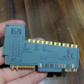
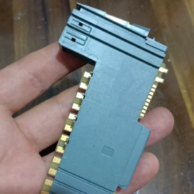
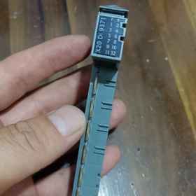
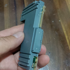
Spiegazione del codice modello
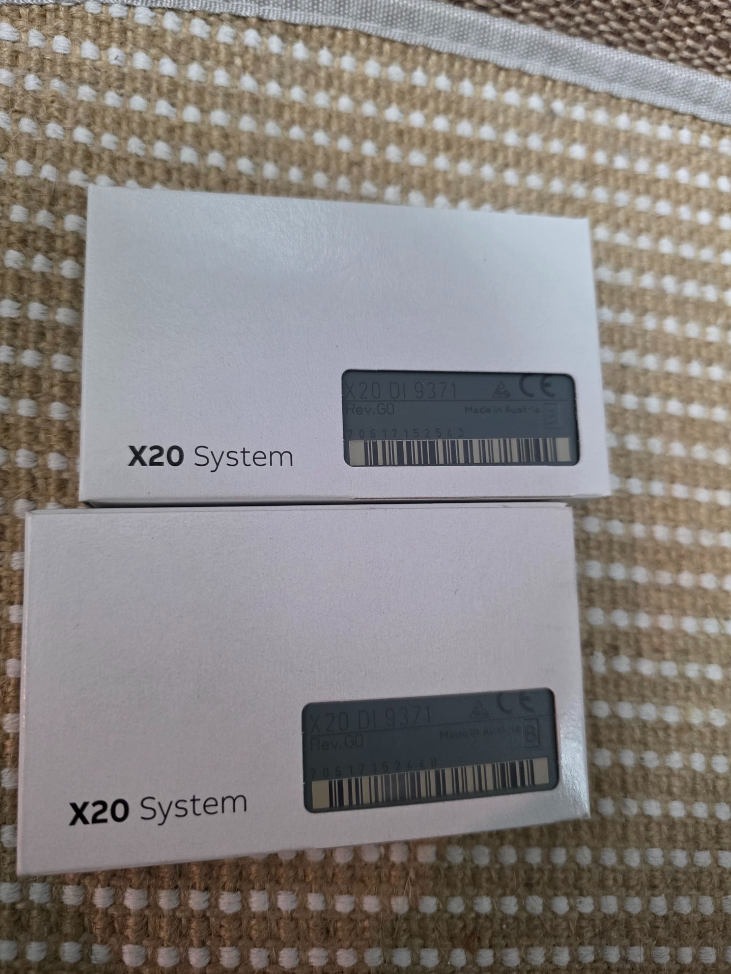
X20DI9371
X20: Piattaforma del sistema I/O distribuito X20
DI: Ingresso digitale
9371: Codice delle specifiche del modulo
- Elettrico principale & Specifiche dell'hardware
| Articolo | Specifica |
| Numero di canali | 16 ingressi digitali |
| Tipo di ingresso | 24 Affondamento della VCC / compatibile con l'approvvigionamento, CEI 61131-2 Tipo 3 |
| Tensione di ingresso nominale | 24 VCC (raggio d'azione: 18~30 VCC) |
| Impedenza di ingresso | ca. 3.9 kΩ |
| Logica attiva (1) Soglia | ≥11 VCC |
| Logica disattivata (0) Soglia | ≤5 VCC |
| Corrente di ingresso per canale | ≈6 mA a 24 VCC |
| Ritardo di risposta | Tipico 0.1 SM; filtro hardware configurabile: 0.1 / 0.5 / 3 / 15 SM (impostazione dei parametri tramite software) |
| Metodo di isolamento | Isolamento del gruppo: 4 canali per gruppo, totale 4 gruppi isolati |
| Tensione di isolamento tra gruppi: 500 VCA | |
| Interfaccia bus | X20 Collegamento del bus di sistema interno |
| Indicazione dello stato | LED indipendenti per ciascun canale; LED di alimentazione del modulo |
| Consumo energetico | Tip. 1.8 W |
- Meccanico & Specifiche ambientali
Montaggio: Standard 35 Guida DIN da mm, installazione orizzontale
Dimensioni: W 40 mm × H 100 mm×D 76.5 mm
Temperatura operativa: -20 ℃ ~ +60 ℃ (all'interno del quadro elettrico)
Magazzinaggio / Temperatura di trasporto: -40 ℃ ~ +85 ℃
Classe di protezione: IP20 (solo per installazione in armadio)
Certificazioni: CE, UL 508, Certificazione marina GL, conforme alla norma EN 61000 Standard industriali EMC
- Struttura interna & Definizione del terminale
16 canali divisi in 4 gruppi isolati:
Gruppo1: CH0~CH3
Gruppo2: CH4~CH7
Gruppo3: CH8~CH11
Gruppo4: CH12~CH15
⚠️ Importante regola di cablaggio: Il terminale comune di un gruppo isolato deve condividere lo stesso 24 Polarità V; NON collegare separatamente, non referenziato 24 Alimentazioni V a diversi gruppi isolati, altrimenti la differenza di potenziale potrebbe danneggiare il circuito di isolamento.
Configurazioni di cablaggio
- Ingresso di approvvigionamento (PNP Sensore)
L'uscita del sensore si collega al terminale DI del modulo; I terminali comuni del modulo si collegano a 0 V(GND)
- Ingresso in calo (Sensore NPN)
Il terminale di alimentazione del sensore si collega a 24 V+, uscita del sensore al terminale DI; i terminali comuni del modulo si collegano a +24V
- Principio di funzionamento
Segnale del sensore digitale esterno → Circuito filtro hardware RC front-end → Gruppo di isolamento optoaccoppiatore → Circuito di modellazione del segnale → Chip di comunicazione bus X20
Il controller legge ciclicamente lo stato del canale tramite la CPU X2X/X20. I parametri del tempo di filtro possono essere configurati in Automation Studio per sopprimere il rimbalzo dei contatti e gli impulsi di interferenza generati dagli inverter.
- Informazioni sul software
Software di programmazione: Studio di automazione 4.0 e tutte le versioni successive supportate
Identificazione dell'hardware: Libreria integrata per la descrizione del dispositivo X20 standard, non è richiesto alcun file GSD aggiuntivo
Elabora immagine: Mappatura automatica degli indirizzi dei canali; supportare la forzatura del segnale & monitoraggio del segnale in linea
Funzioni supportate: Diagnosi del canale (nessun rilevamento della rottura del filo, X20DI9371 non supporta la diagnosi di rottura del cavo)
- Confronto dei modelli & Sostituzione compatibile
Confronto con modelli simili della serie X20
| Modello | Canali | Funzionalità di isolamento | Caratteristiche |
| X20DI9371 | 16DI | 4 canali per gruppo isolato | Modulo standard per uso generale, ampiamente utilizzato nei progetti |
| X20DI9372 | 16DI | Isolamento galvanico individuale a canale intero | Per ambienti ad alta interferenza, segnali multipli con potenziali diversi |
| X20DI4371 | 4DI | 4 canali per gruppo isolato | Modulo compatto per punti I/O limitati |
✅ Condizioni di sostituzione diretta
Se X20DI9371 viene utilizzato in progetti esistenti:
Aggiornamento per prestazioni anti-interferenza più elevate: X20DI9372 (compatibile con l'assegnazione dei pin, nessuna modifica del programma richiesta, cablaggio completamente intercambiabile; l'unica differenza è la prestazione di isolamento migliorata)
❌ Non direttamente intercambiabile: X20DI4371 ha una diversa quantità di canali e disposizione dei terminali dell'unità base
- Scenari applicativi tipici
Macchine utensili, macchine per l'imballaggio, trasportatori per la movimentazione dei materiali, gomma & attrezzature in plastica, trattamento dell'acqua, linee di produzione di automazione generale
Acquisizione del segnale: Interruttori di prossimità, sensori fotoelettrici, finecorsa, pulsanti, contatti relè passivi
- Linee guida per l'installazione & Risoluzione dei problemi
Divieti severi
- Non applicare mai una tensione superiore a 30 VCC, danneggerà permanentemente i circuiti di ingresso
- Non collegare due masse non comuni 24 Alimentazioni V a diversi gruppi isolati
- Evitare la posa parallela dei cavi di segnale e di potenza (forti interferenze elettriche causano segnali tremolanti)
Difetti comuni
- Il LED del canale è sempre acceso: Cavo del segnale in cortocircuito a terra; Alimentazione anomala del sensore PNP
- Fluttuazione intermittente del segnale: Grave interferenza elettromagnetica → aumentare il tempo di filtraggio dell'hardware; controllare la schermatura & messa a terra
- Tutti i canali di un gruppo non hanno segnale: Perdita di alimentazione al terminale comune del gruppo corrispondente
- Unità base compatibili
Base standard: X20BM01 (base con morsetti a vite)
Base opzionale: X20BM11 (terminale a connessione rapida a molla)
La base deve essere ordinata separatamente; la base morsettiera NON è inclusa nel modulo!
X20DI9371 Assegnazione pin terminale
Base compatibile: X20BM01 (vite) / X20BM11 (terminale a molla)
16 canali divisi in 4 gruppi galvanicamente isolati (4 canali ciascuno)
Gruppo1: CH0~CH3|Gruppo2: CH4~CH7|Gruppo3: CH8~CH11|Gruppo4: CH12~CH15
Sequenza terminale (Dall'alto verso il basso sulla base)
Gruppo 1 (CH0~CH3)
1: DI0
2: DI1
3: DI2
4: DI3
5: COM0 (Terminale comune per il Gruppo1)
Gruppo 2 (CH4~CH7)
6: DI4
7: DI5
8: DI6
9: DI7
10: COM1 (Terminale comune per il Gruppo2)
Gruppo 3 (CH8~CH11)
11: DI8
12: DI9
13: DI10
14: DI11
15: COM2 (Terminale comune per il Gruppo3)
Gruppo 4 (CH12~CH15)
16: DI12
17: DI13
18: DI14
19: DI15
20: COM3 (Terminale comune per il Gruppo4)
Riepilogo delle specifiche di cablaggio
- Sensore PNP (Ingresso di approvvigionamento, Standard di settore)
Tutte le porte COM0/COM1/COM2/COM3 → collegate 24 VCC 0 V(GND)
Cavo del segnale del sensore a DIx, terminale positivo del sensore a 24 V+
- Sensore NPN (Ingresso in calo)
Tutte le porte COM0/COM1/COM2/COM3 → collegate +24 VCC
Cavo del segnale del sensore a DIx, terminale negativo del sensore a 0 V
⚠️ Importante: COM0/COM1/COM2/COM3 sono isolate galvanicamente tra loro.
Non collegare terminali COM diversi ad alimentatori con potenziale di terra non condiviso!
Passaggi per configurare il filtro di ingresso in Automation Studio
- Individua X20DI9371 nell'albero del progetto e fai doppio clic per aprire la finestra di configurazione
- Nome del parametro: Tempo di filtro in ingresso
Opzioni selezionabili:
0.1 SM (risposta rapida, per segnali ad alta velocità)
0.5 SM
3 SM (consigliato per pulsanti normali & interruttori di prossimità)
15 SM (ambiente con forti interferenze, sopprimere il rimbalzo dei contatti)
- Scarica progetto; i parametri hanno effetto immediato senza spegnere e riaccendere



NH42-63-318x560.png "Commutatori automatici di tipo PC CHINT (ATS)NH42-63/4SZ")



