 Contattore,interruttore automatico,inverter solare,contatore elettrico,batterie solari

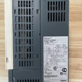
Interpretazione completa del modello
| Segmento modello | Descrizione |
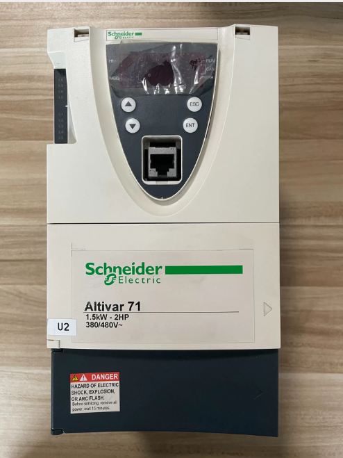
| ATV71 | Serie di prodotti: Schneider Altivar 71 high-performance frequency converter, designed for complex, high-power mechanical equipment, primarily replacing the ATV58/68 series |
| H | Voltage Class: Three-phase 380~480V (50/60Hz) |
| C | Application Type: Constant Torque application, suitable for high-torque scenarios such as hoisting, lifting, and material handling |
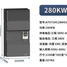
| 28 | Power Code: Corresponding to a rated motor power of 280kW (some documents indicate compatibility with 315kW motors) |
| N4 | Configurazione standard: Built-in Class B EMC filter, IP20 protection class, no built-in braking unit |
| (Z) | Special Identifier: Indicates聽no built-in graphic display terminal, only equipped with a basic operation panel |
- Parametri tecnici fondamentali
| Elemento parametro | Valore | Osservazioni |
| Rated Input Voltage | Three-phase 380~480V, 50/60Hz | Allowable fluctuation range: -15%~+10% |
| Rated Output Power | 280kW (compatible with 315kW motors) | Rated value for constant torque applications |
| Rated Output Current | 550UN | Continuous output current at 2.5kHz carrier frequency |
| Instantaneous Output Current | 825UN (for 60 secondi) | 150% of rated current, suitable for heavy-duty starting |
| Maximum Output Frequency | 600Hz | Meets the control requirements of high-speed motors |
| Control Modes | V/F open-loop, vector control (opzionale) | Supports multiple motor control algorithms for different application scenarios |
| Built-in Components | Class B EMC filter, basic operation panel | The Z version has no graphic display terminal; the VW3A1101 graphic terminal needs to be purchased separately |
| Classe di protezione | IP20 | Suitable for installation inside electrical control cabinets |
| Accessori consigliati | NSX630 circuit breaker, LC1F630 contactor are recommended | Ensure the safe operation of the electrical system |
III. Caratteristiche principali del prodotto
- High Torque Performance: Specifically designed for constant torque loads, with a starting torque of up to 150% of the rated torque, ideal for equipment requiring stable torque output such as cranes, ascensori, and conveyor belts
- Flexible Control Functions: Supports 8 preset speeds, PID regulator, and brake control logic to meet complex motion control requirements
- Integrated Communication Capability: Built-in Modbus and CANopen communication interfaces; support for industrial networks such as Profibus and Ethernet via expansion cards
- Comprehensive Protection Mechanism: Equipped with full protection functions including overcurrent, sovratensione, sottotensione, overheating, cortocircuito, and ground fault protection, effectively safeguarding the frequency converter and motor
- Manutenzione facile: Built-in diagnostic functions for quick fault location; modular design facilitates repair and component replacement
- Application Scenarios and Compatible Equipment
- Main Application Fields:
Hoisting Machinery: Bridge cranes, tower cranes, port cranes, ecc.
Lifting Equipment: Ascensori, escalators, mine hoists, ecc.
Material Handling: Trasportatori a nastro, bucket elevators, screw conveyors, ecc.
Other High-torque Equipment: Packaging machinery, woodworking machinery, high-inertia load equipment
- Not Suitable For:
Light-load or fan/pump type variable torque applications (the ATV71D series is recommended)
Unprotected outdoor installation (additional protective enclosures are required)
Scenarios requiring frequent braking (external braking units need to be configured separately)
- Key Selection and Usage Precautions
- Model Differentiation:
ATV71HC28N4: Equipped with a basic operation panel, no graphic terminal
ATV71HC28N4Z: Explicitly marked without a graphic terminal, with the same configuration as the above model
ATV71HD28N4: Constant torque version with a graphic terminal
- Requisiti di installazione:
Must be installed inside an electrical control cabinet with IP20 protection class
Sufficient heat dissipation space must be reserved (more than 100mm on all sides: top, bottom, left and right)
An input reactor is recommended on the input side to reduce harmonic interference
- Accessory Purchase:
Graphic Display Terminal: VW3A1101 (applicable to models without the Z identifier)
Braking Unit: VW3A3520 (applicable to scenarios requiring frequent braking)
Communication Expansion Cards: VW3A3306 (Profibus DP), VW3A3310 (Ethernet), ecc.
- Product Status Description
This model was discontinued on March 31, 2020. Schneider recommends the ATV930 series as a replacement product (model ATV930C28N4Z), which features more advanced control algorithms, higher energy efficiency, and more comprehensive communication functions.
Installazione, Wiring Guide and Troubleshooting Manual for Schneider ATV71HC28N4(Z) Frequency Converter
- Key Installation Guidelines
1.1 Preparazione pre-installazione
Safety Prerequisites: Only operated by certified electricians. Disconnect all power supplies before installation and wait for 15 minutes to allow the DC bus capacitors to discharge completely (voltaggio < 45Vcc)
Requisiti ambientali:
Temperatura: -10°C fino a +40°C (derate by 1% for every 1°C increase above 40°C)
Umidità: 5%-95% without condensation
Altitudine: ≤1000m (derate by 1% for every 100m increase above 1000m)
Classe di protezione: IP20 (cabinet installation), garantire una buona ventilazione
Tool Preparation: Multimetro, 1000V megaohmmetro, chiave dinamometrica, strumento di crimpatura, nastro isolante
1.2 Mechanical Installation
Metodo di installazione: Deve essere installato verticalmente, with 150mm heat dissipation space reserved on all sides (top, bottom, left and right)
Fixing Requirements: Secure with M12 bolts at a torque value of 50Nm to ensure stability and no vibration
Cooling System:
Equipped with built-in fan cooling; ensure air inlets are unobstructed
Clean dust in the air duct regularly (ogni 3 mesi)
Install external cooling equipment when the ambient temperature exceeds 40°C
1.3 Collegamento elettrico (Core Steps)
| Connection Terminal | Funzione | Connection Requirements |
| R/L1, S/L2, T/L3 | Three-phase input power (380-480V) | 1. Connect to NSX630 circuit breaker (raccomandato) |
| 2. Copper core cable with cross-sectional area ≥240mm² | ||
| 3. Torque value: 60Nm | ||
| U, V, W | Three-phase output (connected to motor) | 1. Copper core cable with cross-sectional area ≥240mm² |
| 2. Motor power ≤315kW | ||
| 3. Torque value: 60Nm | ||
| 4. Cable length ≤100m (no filter required) | ||
| PA, PC | DC bus terminals | 1. Connect to the built-in DC reactor |
| 2. External power supply is prohibited | ||
| PO, PC | Braking resistor terminals | 1. Connect only when rapid braking is required |
| 2. Braking resistor power ≥15kW | ||
| +24V, GND | Controllare l'alimentazione | 1. Connect to 24V DC power supply |
| 2. Copper core cable with cross-sectional area ≥2.5mm² | ||
| AI1-AI2 | Analog input | 1. Connected with shielded cable |
| 2. Shield layer grounded at one end | ||
| DI1-DI6 | Digital input | 1. Dry contact or PNP/NPN signal |
| 2. Copper core cable with cross-sectional area ≥1.5mm² | ||
| DO1-DO3 | Digital output | 1. Uscita relè (250VAC/30VDC) |
| 2. Maximum current: 5UN | ||
| PE | Protective grounding | 1. Copper core cable with cross-sectional area ≥95mm² |
| 2. Must be connected to the system grounding bar | ||
| 3. Torque value: 60Nm |
Connection Notes:
- Route input and output cables separately (distance ≥300mm) per evitare interferenze elettromagnetiche
- Use shielded cables for control circuits, with the shield layer grounded at one end (on the frequency converter side)
- Perform a tensile test on all terminal connections to ensure no looseness
- Install a surge suppressor on the motor side (opzionale)
1.4 Cablaggio del circuito di controllo
Basic Control Circuit:
Connect the start (DI1), fermare (DI2), and forward/reverse (DI3) terminali
Ensure the emergency stop circuit is independent of the frequency converter control
Communication Connection:
ModBus: Connect to RS485 terminals (+, -) with a baud rate of 9600-19200bps
Profibus: Install the optional VW3A3407 communication card
- Wiring Inspection and Commissioning Process
2.1 Ispezione del cablaggio
- Insulation Test:
Insulation resistance between input/output terminals and ground ≥1MΩ (tested with 1000V megohmmeter)
Motor winding insulation resistance ≥1MΩ
- Continuity Test:
Check that there is no short circuit between input and output terminals
Verify normal continuity of control circuit terminals
- Impostazione dei parametri:
Restore factory settings (P0.01=1)
Set motor parameters (P1.01-P1.07): rated power, voltaggio, attuale, frequenza
Set control mode (P2.01=0: V/F control; =1: vector control)
2.2 Commissioning Steps
- No-load Commissioning:
Disconnect the motor, start the frequency converter, and check for balanced output voltage
Test the frequency adjustment range (0-60Hz)
- Loaded Commissioning:
Connect the motor, set acceleration time (P4.01=10s) and deceleration time (P4.02=15s)
Gradually load up to 100% and check for normal current and temperature
Test overload capacity (150% of rated current for 60 secondi)
- Troubleshooting Manual
2.1 Fault Diagnosis Process
- Fault Identification: Record fault codes, operating status at the time of fault, and parameter settings
- Preliminary Inspection:
Power off and check for loose wiring and insulation damage
Inspect the cooling system and dust in the air duct
Measure power supply voltage and motor insulation
- Targeted Troubleshooting: Identify causes based on fault codes
- Solution Implementation: Repair or replace faulty components
- Verification Test: Conduct trial operation after fault elimination to confirm no abnormalities
2.2 Common Fault Codes and Solutions (Core Content)
| Fault Code | Fault Type | Possibili cause | Soluzioni |
| SCF1 | Motor Short Circuit | 1. Motor winding short circuit | 1. Test motor insulation with a megohmmeter |
| 2. Output cable damage | 2. Inspect cables and replace damaged parts | ||
| 3. IGBT module damage | 3. Run transistor test (Menu 1.10) | ||
| 4. Replace IGBT module | |||
| SCF2 | Ground Short Circuit | 1. Motor or cable grounding | 1. Check motor grounding resistance ≥1MΩ |
| 2. Internal grounding of frequency converter | 2. Test insulation between output terminals and ground | ||
| 3. Replace damaged components | |||
| OCF | Sovracorrente | 1. Sudden load change | 1. Extend acceleration time (P4.01) |
| 2. Excessively short acceleration time | 2. Inspect load and eliminate mechanical faults | ||
| 3. Incorrect motor parameters | 3. Reconfigure motor parameters | ||
| 4. Check current detection circuit | |||
| OLF | Motor Overload | 1. Load exceeds rated value | 1. Reduce load or operate at derated capacity |
| 2. Incorrect motor thermal protection parameters | 2. Set correct motor thermal current (ITH) | ||
| 3. Poor heat dissipation | 3. Clean air duct and improve heat dissipation | ||
| 4. Inspect motor cooling fan | |||
| OHF | Frequency Converter Overheating | 1. Excessively high ambient temperature | 1. Improve ventilation and reduce ambient temperature |
| 2. Fan damage | 2. Inspect fan and replace damaged parts | ||
| 3. Air duct blockage | 3. Clean dust from air duct | ||
| 4. Check temperature sensor | |||
| USF | Sottotensione | 1. Input voltage below 340V | 1. Check grid voltage and install a voltage stabilizer if necessary |
| 2. Pre-charging resistor damage | 2. Inspect pre-charging circuit | ||
| 3. Power supply fluctuation | 3. Extend pre-charging time | ||
| 4. Replace damaged resistor | |||
| OSF | Sovratensione | 1. Input voltage above 480V | 1. Check grid voltage |
| 2. Excessively short deceleration time | 2. Extend deceleration time (P4.02) | ||
| 3. Braking unit fault | 3. Inspect braking unit and resistor | ||
| 4. Activate voltage suppression function | |||
| PHF | Input Phase Loss | 1. Phase loss in input power supply | 1. Check three-phase voltage balance |
| 2. Circuit breaker fault | 2. Inspect circuit breaker and contactor | ||
| 3. Input contactor fault | 3. Replace damaged components | ||
| 4. Check LCF parameter settings | |||
| EnF | Encoder Fault | 1. Loose encoder connection | 1. Inspect encoder wiring |
| 2. Encoder damage | 2. Test encoder signal | ||
| 3. Incorrect parameter settings | 3. Reconfigure encoder parameters | ||
| 4. Replace encoder |
2.3 Advanced Troubleshooting
Parameter Faults:
When “Invalid Setting” is displayed, press the ENT key twice to restore factory parameters
When parameters are corrupted, restore factory settings via P0.01=1
Communication Faults:
Check for loose communication cable and connectors
Confirm that baud rate and address settings match the host system
Test communication module and replace faulty modules
Hardware Faults:
Power Module Fault: Measure DC bus voltage (normal range: 540-600V)
Control Board Fault: Inspect indicator lights and replace control board if necessary
Driver Board Fault: Replace driver board and perform re-commissioning
III. Maintenance Schedule
| Ciclo di manutenzione | Maintenance Content | Note |
| Daily | Check operating status, parameters, and temperature | Record any abnormalities |
| Weekly | Clean surface dust and inspect cooling fans | Ensure fans are operating normally |
| Mensile | Check for loose wiring and cable insulation | Perform torque check on terminal connections |
| Trimestrale | Clean dust in air duct and inspect insulation resistance | Use compressed air for dust cleaning |
| Annual | Comprehensive inspection and replacement of wearing parts (tifosi, capacitors) | Must be performed by professional personnel |
| Biennial | Capacitor performance test and full-machine commissioning | Replace capacitors if necessary |
 and 6ES7 235-0KD22-0XA8 (China CN), both hardware version 22 spare parts for S7-22X CPU maintenance.")


")


NH42-63-318x560.png "Commutatori automatici di tipo PC CHINT (ATS)NH42-63/4SZ")


