 Contattore,interruttore automatico,sensore,Codificatore,PLC,Convertitore

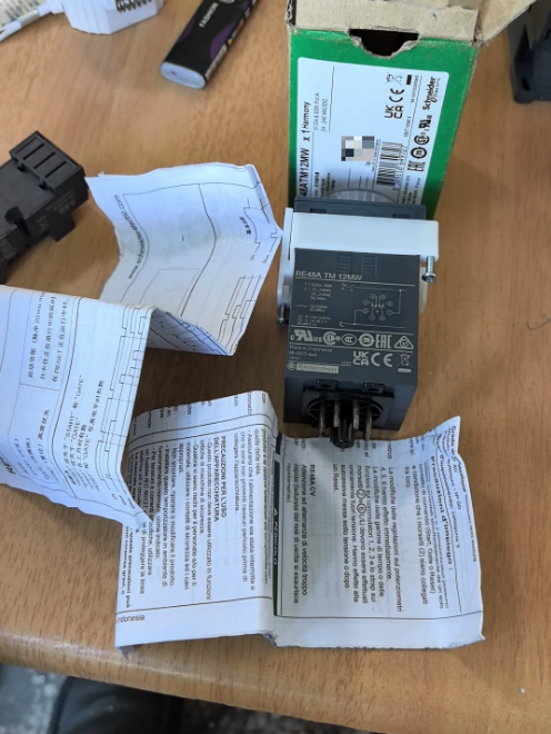

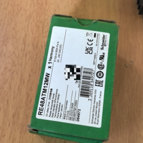

Schneider RE48ATM12MW Time Delay Relay Installation Manual
Nome completo del prodotto: Harmony RE48A Series Electronic On-Delay Time Relay
Modello: RE48ATM12MW (8-spillo, 2 contatti di scambio, 24~240 V CA/CC, On-Delay only)
Nota: This manual is compiled based on Schneider official datasheet, available for on-site installation, commissioning and document filing.
Sommario
RE48ATM12MW
RE48A: Harmony RE48A series, 48×48mm panel-mount electronic time delay relay
T: Ritardo (single function, power-on delay only)
M: Wide supply voltage 24…240V AC/DC
12: 2 contatti di scambio (2C/O)
W: 8-pin plug-in socket interface
Core Definition: Single-function On-Delay Relay. It cannot be switched to off-delay, pulse or flashing modes.
- Principali Specifiche Elettriche
| Articolo | Specifica |
| Modalità funzione | Ritardo (Mode A) |
| Tensione di alimentazione | 24~240V AC/DC Universal (AC & Compatibile con CC) |
| Contact Output | 2 set di contatti di scambio (2C/O, DPDT), AgNi cadmium-free contacts |
| Corrente di contatto nominale | 5UN / 250V e (AC-12); 1.5E AC-15; 2A/30V DC-13 |
| Adjustable Delay Range | 0.02s ~ 300h, selectable front panel ranges: |
| 0.02–1.2s / 0.05–3s / 0.2–12s / 0.5–30s / 2–120s / 5–300 | |
| 0.2–12min / 0.5–30min / 2–120min /5–300min | |
| 0.2–12h / 0.5–30h / 2–120h /5–300h | |
| Ripeti la precisione | ±0.2% of full scale |
| Consumo energetico | 0.5W(24V) ~ 1.7W(240V) |
| Resistenza meccanica | 30 milioni di operazioni; Resistenza elettrica (5Un carico resistivo): 100,000 operazioni |
| Protezione dall'ingresso | Front face IP50, housing IP40 |
| Ritaglio del pannello | Standard 48×48mm instrument cutout |
| Interfaccia | 8-pin circular socket |
| Peso netto | ca. 140G |
- Logica operativa (Ritardo)
- Power applied to A1/A2 → timing starts;
- Before timing elapses: contacts remain in initial state;
- When preset delay expires: both sets of changeover contacts operate simultaneously;
⚠️ Importante: Front panel DIP selector
Posizione 1: Both outputs timed
Posizione 2: One timed output, the other instantaneous upon power-up
- Power removal resets the relay; timing restarts after re-energization.
- Matching Sockets & Accessori
Socket is NOT supplied with relay and must be ordered separately:
- DIN rail mounting socket: RUZC2M (8-pin screw terminal, più comune)
- PCB mounting socket: RE48ASOC8SOLD
Accessori opzionali:
RE48ASETCOV: Setting protective cover (prevents unauthorized adjustment)
RE48AIPCOV: IP64 dust & waterproof front cover
- 8-Pin Terminal Definition (RUZC2M Socket)
2, 7: A1, A2 Coil Power Terminals
1-3-4: 1st changeover contact set
8-5-6: 2nd changeover contact set
- Setup Procedure
- Toggle front panel time base selector (s/min/ora)
- Select range limit via rotary knob (per esempio. 30s range)
- Rotate pointer knob to set target delay
- Select operating mode: Dual timed outputs / One timed + one instantaneous output
- Alternative Replacement Models
Sostituzione diretta
- RE48AMH13MW (8-spillo, multi-function version). Supports on-delay, pulse timing and more. Fully interchangeable with the same socket.
Differenza: ATM = On-Delay only; AMH = Multi-function
Compact Alternative (Integrated DIN rail type, no separate socket)
RE22R2AMU (Montaggio su guida DIN, dimensione più piccola, not suitable for 48×48 panel cutout installation)
- Scenari applicativi tipici
Fan & pump startup delay, star-delta motor starting delay
Sequential startup of conveyor systems, equipment power-on buffer delay
HVAC system timing control, lighting delayed switch-on
- Rischi & Divieti
- Do not feed voltage higher than 250V into contact circuits; freewheeling diode recommended for DC inductive loads;
- Brief power interruption <10ms will NOT trigger reset; sufficient power-off duration is required for reliable reset;
- This model has no external reset terminal. Reset can only be achieved by cutting supply power;
- Avoid environments with continuous condensation. Add filtering if installed close to inverters for EMC suppression.
- Istruzioni di sicurezza (Mandatory Reading)
- Panoramica del prodotto & Descrizione del modello
- Matching Sockets & Selezione degli accessori
- Two Installation Methods & Procedures
- Definizione del terminale & Schema elettrico standard
- Parameter Setting Procedure
- Passaggi di messa in servizio all'accensione
- Specifiche elettriche
- Guida alla risoluzione dei problemi
- Limitazioni all'installazione & Requisiti ambientali
- Safety Instructions ⚠️【Important】
- Cut off upstream power supply before all installation, wiring and disassembly operations. Live working is forbidden;
- Contact circuits must not exceed rated load: 5A/250 V CA. Freewheeling diode is recommended for DC inductive loads;
- Do not deploy in flammable/explosive environments, locations with continuous condensation or corrosive gas;
- No serviceable parts inside the unit. Do not disassemble; replace complete unit upon failure;
- Verify supply voltage before installation: 24~240 V CA/CC. Voltaggio >264V is prohibited;
- Tightening torque for socket terminals: 0.8~1,2 N·m. Avoid over-tightening which cracks plastic base.
- Panoramica del prodotto
Funzione: Single-function On-Delay (Power-On Delay)
Fattore di forma: 48×48mm panel mount, 8-pin plug-in interface
Alimentazione elettrica: Wide range 24…240V AC/DC
Produzione: 2 set di contatti di scambio (2C/O)
Intervallo di ritardo: 0.02s ~ 300h, time base selectable via front panel switch
Grado di protezione: Front IP50, housing IP40
Model Code Recap
RE48A-T-M-12-W
RE48A: 48×48 panel time relay
T: Ritardo (single function)
M: 24~240V AC/DC wide voltage supply
12: 2 contatti di scambio
W: 8-pin circular plug socket
- Matching Socket & Accessori opzionali
Socket is not included with RE48ATM12MW and must be ordered separately
| Nome | Modello | Applicazione |
| DIN Rail Mount Socket | RUZC2M (8-spillo) | Control cabinet DIN rail mounting (most widely used for projects) |
| PCB Solder Socket | RE48ASOC8SOLD | PCB soldering installation |
| Parameter Lock Cover | RE48ASETCOV | Prevent on-site unauthorized time adjustment |
| IP64 Waterproof Front Cover | RE48AIPCOV | Upgrade dust & water resistance for operation panels |
- Two Installation Procedures
Metodo 1: Montaggio su guida DIN (RUZC2M Socket)
- Align clips of RUZC2M socket onto standard 35mm DIN rail, press down until fully locked;
- Loosen socket terminal screws with screwdriver for wiring;
- Complete all cable wiring;
- Vertically align RE48ATM12MW with 8-pin socket, press evenly until fully seated;
Do not force insertion at an angle to prevent bending of contact pins.
Metodo 2: Control Cabinet Panel Cutout Mounting
- Panel cutout dimension: 48⁺⁰·⁶₋₀ mm × 48⁺⁰·⁶₋₀ mm
- Spessore pannello applicabile: 1mm~10mm
- Insert relay body from front of panel through cutout;
- Fit mounting bracket at rear of panel, tighten fixing screws evenly on both sides;
- Connect 8-pin wiring socket from rear side;
Reserve ≥10mm clearance between adjacent devices for heat dissipation.
- 8-Pin Terminal Definition (Standard RUZC2M Socket)
| Terminale n. | Descrizione della funzione |
| 2 | A1 Power Terminal |
| 7 | A2 Power Terminal |
| 1 | Common of 1st contact set COM1 |
| 3 | Timed Normally Open NO1 (1st set) |
| 4 | Timed Normally Closed NC1 (1st set) |
| 8 | Common of 2nd contact set COM2 |
| 6 | Timed Normally Open NO2 (2nd set) |
| 5 | Timed Normally Closed NC2 (2nd set) |
Front Panel Function Selector Switch
Posizione 1: Both outputs timed (Impostazioni di fabbrica)
Posizione 2: One timed output, one instantaneous output upon power-up
Standard Wiring Guide
- Power circuit: Control supply connected to 2,7 (A1/A2)
Alimentazione CA: L and N can be connected to 2/7 arbitrarily, no polarity
DC supply: Positive/negative polarity interchangeable, universal for AC & DC
- Circuito di carico:
Terminale comune 1 → Timed NO 3; Terminale comune 8 → Timed NO 6
Logica operativa: Power applied to 2,7 → timing starts; After preset delay, 1-3 Chiuso, 8-6 Chiuso. Relay resets immediately after power cut.
- Front Panel Parameter Setting Steps
- Energize relay (UP LED indicator lights = standby timing status);
- Time base selector: Choose s / min / H (Seconds / Minutes / Ore);
- Rotate adjustment knob to set target delay duration;
- Toggle function selector: Dual timed outputs / One timed + one instantaneous output;
- Optionally install RE48ASETCOV protective cover to lock parameters.
Available Delay Ranges
0.02–1.2s / 0.05–3s / 0.2–12s / 0.5–30s
2–120s / 5–300 / 0.2–12min / 0.5–30min
2–120min /5–300min /0.2–12h /0.5–30h /2–120h /5–300h
- Power-on Commissioning Procedure
- Check wiring under power-off condition; confirm no short circuit in power and load circuits;
- Switch on power; steady UP LED = timing standby state;
- Wait until preset delay expires;
- Upon delay completion: Contacts switch state;
- Cut power supply to terminals 2,7 for relay reset; timing restarts after re-power;
- Perform multiple cycle tests to verify timing accuracy;
Brief power interruption <10ms cannot reset relay. Complete power cut ≥50ms required for reliable reset.
- Specifiche elettriche principali
| Articolo | Parametro |
| Supply Range | 24~240 V AC/DC, 50/60Hz |
| Valutazione dei contatti | 5A 250V AC-12; 1.5E AC-15; 2A/30V DC-13 |
| Timing Repeat Accuracy | ±0.2% full scale |
| Consumo energetico | 0.5W~1.7W |
| Resistenza meccanica | 30 milioni di operazioni; Resistenza elettrica 100,000 operazioni sotto carico resistivo |
| Temperatura ambiente operativa | -20 ℃ ~ +55 ℃, nessuna condensa |
| Temperatura di conservazione | -40 ℃ ~ +70 ℃ |
- Tabella per la risoluzione dei problemi
| Fenomeno di guasto | Possibili cause | Soluzioni |
| UP LED does not light after power-up | 1. No power on 2/7; 2. Voltage out of range; 3. Poor pin contact | Controllare la tensione di alimentazione, re-seat relay unit, measure voltage at socket terminals 2 & 7 |
| Contacts activate immediately after power-up without delay | Incorrect DIP switch setting; Model confusion (Do not mix up with multi-function RE48AMH) | Verify selector switch position; Confirm model is RE48ATM12MW (On-Delay only) |
| Contacts fail to switch after delay expires | Carico sovraccarico; Contact erosion; Cablaggio allentato | Reduce load current, tighten terminals; Replace relay if contacts are damaged |
| Inaccurate timing duration | Wrong time base range; Temperatura ambiente eccessiva | Reselect correct time base; Migliora la dissipazione del calore |
| Unintended frequent reset | Transient voltage drop or interference on power supply | Add filtering components to stabilize control circuit supply |
- Limitazioni all'installazione & Confini operativi
❌ Forbidden Operations:
- Apply voltage exceeding 250V to contact circuits;
- Mount in close proximity to inverters and large contactors (strong electromagnetic interference);
- Enclosed installation causing heat accumulation; continuous operation above 55 ℃ temperatura ambiente;
- Pull cables to forcibly unplug relay, resulting in bent socket pins;
- Deploy for high-frequency pulse control (accelerates electronic component aging).
✅ Recommendations:
Install surge absorption components in parallel for inductive loads (bobine del contattore); Reserve ventilation space inside control cabinet; Use 0.75~1.5mm² copper cables.
Appendice: Alternative Reference
Direct socket-compatible replacement: RE48AMH13MW (8-pin multi-function model)
Differenza: ATM = On-Delay only; AMH supports on-delay, ritardo di disattivazione, flashing and other modes.



NH42-63-318x560.png "Commutatori automatici di tipo PC CHINT (ATS)NH42-63/4SZ")



