 Contattore,interruttore automatico,inverter solare,contatore elettrico,batterie solari

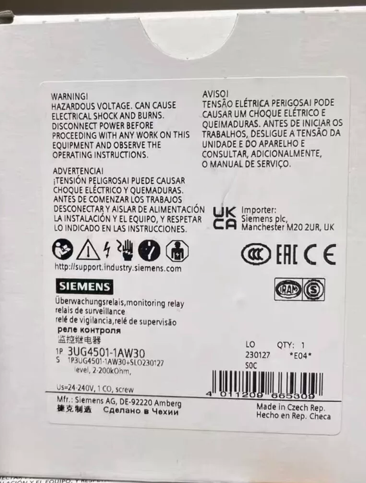

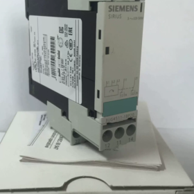
Technical Specification of Siemens 3UG4501-2AW30 Level Monitoring Relay
3UG4501-2AW30 is a mainstream resistance-type level monitoring relay of the Siemens SIRIUS series. It features dual-level control for upper and lower limits, adopts industry-standard DIN rail mounting and spring-cage terminals, and supports wide-range power supply of 24~240V AC/DC. Widely applied to industrial water tanks, sewage pools, chemical storage tanks and other facilities, it realizes high/low level alarm, automatic water filling and draining, as well as overflow and dry-run protection. It is also a highly searched and widely used control component for level monitoring in industrial control sites.
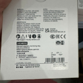
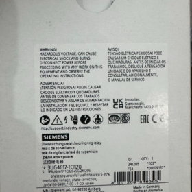
- Model Code Decoding (Core Basis for Model Selection)
Each character of the model represents hardware, function and structural attributes, which is the key to distinguish products in the same series. The detailed breakdown is as follows:
| Segmento di codice | Character | Detailed Definition & Technical Notes for Selection |
| 3UG | 3UG | Standard monitoring relay series of Siemens SIRIUS, specially designed for analog, level and resistance signal monitoring |
| 4 | 4 | Tipo di prodotto: Analog monitoring unit focusing on resistance/level signal acquisition, differentiated from current and voltage monitoring models |
| 5 | 5 | Housing width: Compact 22.5mm design, compatible with standard control cabinet rails to save installation space |
| 1 | 1 | Versione dell'hardware: Standard universal version without customized functions, featuring large market circulation and high compatibility |
| 2 | 2 | Control points: 2-point control (upper limit + lower limit) for simultaneous high and low level monitoring; Cifra 1 stands for single-point control |
| UN | UN | Tipo di funzione: Dedicated for level/resistance monitoring, no additional delay or communication expansion modules |
| W | W | Tipo di terminale: Spring-cage terminal, enabling fast wiring and excellent vibration resistance, ideal for sites with frequent maintenance and severe vibration; Letter A refers to traditional screw terminal |
| 30 | 30 | Codice delle specifiche di base: Standard circuit structure without customized voltage or contacts |
Nota tecnica: Prioritize distinguishing “2/1” (control points) E “W/A” (tipo di terminale) during selection. Spring-cage terminals (W) are recommended for pump rooms with heavy vibration and outdoor control cabinets.
- Funzioni principali & Principio di funzionamento
2.1 Funzioni principali
This level monitoring relay collects the equivalent resistance of conductive liquid via electrodes to implement two major control functions:
Dual-threshold monitoring: Independent settings for upper level limit and lower level limit. The contacts will act once the level exceeds the set limits to trigger alarms or interlock water pumps and valves.
Anti-chatter delay: Built-in adjustable operating delay ranging from 0.5s to 10s, which filters liquid level fluctuation and transient electrode interference to avoid frequent false tripping.
Isolamento elettrico: Complete isolation between the input monitoring circuit and output contact circuit, delivering strong anti-interference performance for sites with inverters, motors and other high-interference equipment.
2.2 Principio di funzionamento
The liquid level of conductive fluid changes the contact area between electrodes, thus generating different equivalent resistance (campo di misura: 2kΩ ~ 200kΩ). The internal circuit of the relay collects resistance signals in real time and compares them with preset thresholds. A resistance value below the lower threshold is judged as low liquid level, while a value above the upper threshold is judged as high liquid level. Finally, the changeover contacts are driven to complete on-off control.
- Full-range Technical Parameters (Including Operating Boundary Notes)
| Categoria dei parametri | Specifiche | Technical Explanation & Boundary Reminders |
| Measuring Parameters | Monitoring resistance range: 2 kΩ ~ 200 kΩ | Suitable for clean water, sewage and weakly acidic/alkaline conductive liquids. Not recommended for liquids with high concentration of acid and alkali beyond the measuring range |
| Parametri di alimentazione | Tensione nominale: 24~240V AC/DC, 50/60Hz | Wide voltage design for global application. No need to distinguish AC and DC, ensuring high fault tolerance for on-site wiring |
| Consumo energetico | ≤2 VA @ DC24V; ≤4 VA @ AC240V | Basso consumo energetico, no heat generation during long-term standby, suitable for 24-hour continuous operation |
| Caratteristiche operative | Continuously adjustable delay: 0.5~10s | A delay of 3~5s is recommended for sites with strong interference or drastic liquid level fluctuation to prevent false triggering |
| Output Contacts | 1 contatto di scambio (1CO); AC-15: 3A/250V; DC-13: 1A/24V | Passive dry contacts only for secondary circuit control. Do not drive high-power loads directly |
| Accuracy Index | Measuring accuracy: ±20%; Temperature drift: 1%/℃ | Measurement error increases gradually when ambient temperature exceeds 40℃. Reserve threshold margin for areas around high-temperature storage tanks |
| Dimensioni complessive | 22.5×92×91mm (L×A×P) | Standard DIN rail mounting with universal cabinet layout. No cabinet modification required for replacement of old models |
| Condizioni ambientali | Temperatura operativa: -25℃ ~ +60 ℃; Classe di protezione: IP20 | For indoor cabinet installation only, not exposed to rain. Abnormal circuit operation may occur below -25℃ |
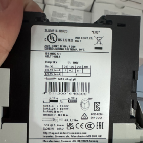
| Prestazioni anti-interferenza | Surge withstand: 4kV; Electrical isolation between input and output | Conforme agli standard EMC industriali, can be installed in the same cabinet with inverters and contactors |
| Specifiche di cablaggio | Spring-cage terminals, compatible with solid wires of 0.5~4mm² | Crimp terminals are required for stranded wires to prevent poor contact |
- Installazione & Specifiche di cablaggio (Wiring Method for Level Relay)
4.1 Requisiti di installazione
Adopt standard snap-on DIN rail mounting. Keep the installation spacing ≥5mm for ventilation and heat dissipation. Reserve operating space on the front of the device for potentiometer adjustment.
4.2 Wiring Division (Two Independent Circuits, Strict Separation Required)
- Power Supply Circuit: Connect to 24~240V AC/DC power supply. No polarity limitation due to wide voltage compatibility.
- Electrode Monitoring Circuit: Connect external level electrodes for resistance signal measurement. Shielded cables are recommended and routed away from power cables.
- Output Contact Circuit: Collegare 1 set of changeover contacts to alarm lamps, relay coils and water pump control circuits for secondary low-voltage control.
Attenzione: Never route monitoring cables and power cables in the same conduit. Electromagnetic interference will occur and directly cause frequent false tripping of the relay.
- Confronto dei modelli & Soluzioni sostitutive (List of Main Alternative Models)
Comparison of different versions in the same series and similar models, commonly referenced for procurement replacement and equipment renovation:
| Modello | Control Points | Tipo di terminale | Differenze fondamentali | Replacement Feasibility |
| 3UG4501-2AW30 (Questo modello) | 2 punti (Superiore & lower limits) | Spring-cage terminal | Dual-level control with anti-vibration wiring | Reference standard model |
| 3UG4501-2AA30 | 2 punti (Superiore & lower limits) | Terminale a vite | Funzioni identiche, only different wiring mode | Direttamente intercambiabile, only wiring adjustment needed |
| 3UG4501-1AW30 | 1 punto (Single threshold) | Spring-cage terminal | Only single level monitoring without upper/lower limit function | Incomplete functions, cannot replace this model directly |
| 3UG4501-1AA30 | 1 punto (Single threshold) | Terminale a vite | Single-point monitoring + terminale a vite | Mismatched functions, replacement prohibited |
Cross-brand replacement reference: Equivalent resistance-type level monitoring relays from Weidmüller and Phoenix Contact are compatible if power supply and contact parameters are consistent. Verify the measuring resistance range before replacement.
- On-site Commissioning & Impostazione dei parametri
- Threshold Adjustment: Rotate the front panel potentiometer to set the lower limit resistance (low liquid level) and upper limit resistance (high liquid level) rispettivamente, and fine-tune according to the conductivity of on-site liquid.
- Delay Setting: Turn clockwise to increase the delay (3~5s recommended) for severe liquid level fluctuation and strong interference; set 0.5~1s for static clean water conditions.
- Power-on Test: Simulate high and low liquid level conditions, check contact switching and actuation of alarm devices. Put into formal operation after confirming correct logic.
- Fault Analysis & Risoluzione dei problemi (Core Troubleshooting Content)
Analyze root causes based on electrical principles and provide step-by-step solutions for common on-site faults:
| Fenomeno di guasto | Root Technical Causes | Soluzioni passo dopo passo |
| No relay operation, contacts fail to switch | 1. Power supply voltage out of 24~240V range; 2. Scaled or corroded electrodes leading to over-limit resistance; 3. Cablaggio allentato | 1. Measure power supply with multimeter and rectify power circuit; 2. Remove and clean scaled/corroded electrodes, replace damaged ones; 3. Retighten spring terminals and check for broken wires |
| Normal liquid level but frequent false tripping | 1. Leakage between electrodes or liquid level fluctuation; 2. Electromagnetic interference from power cables; 3. Excessively short operating delay | 1. Extend operating delay to over 3s; 2. Replace monitoring cables with shielded wires and single-end grounding; 3. Clean electrodes to eliminate surface leakage |
| Contacts act but rear-end loads do not work | Aged or burned contacts; load current exceeds rated contact current | 1. Cut off power and test contact continuity, replace the relay if contacts are damaged; 2. Add intermediate relays for current expansion. Never drive high-power loads directly via the contacts |
- Domande frequenti (Domande frequenti)
Q1: How to choose between relays with spring-cage terminals and screw terminals?
UN: Spring-cage terminals are preferred for vibration-prone sites such as pump rooms and vehicle-mounted equipment due to fast wiring and good vibration resistance. Screw terminals are suitable for permanently installed cabinets with rare maintenance for more stable connection.
Q2: Can this level monitoring relay directly replace the old model 3UG3501?
UN: SÌ, it is electrically fully compatible with consistent installation dimensions and wiring logic. As an upgraded model with identical functions, no circuit modification is required for replacement.
Q3: Why does the level relay frequently trip near inverters?
UN: Inverters generate high-frequency electromagnetic interference which couples into electrode signal cables. Soluzioni: Route monitoring cables separately, use shielded cables and appropriately extend the operating delay.
Q4: What happens if the measured resistance exceeds 200kΩ?
UN: The device cannot identify level signals beyond the measuring range, continuously judges the state as high liquid level, keeps contacts actuated and loses monitoring function.


")


NH42-63-318x560.png "Commutatori automatici di tipo PC CHINT (ATS)NH42-63/4SZ")


