 Contattore,interruttore automatico,sensore,Codificatore,PLC,Convertitore

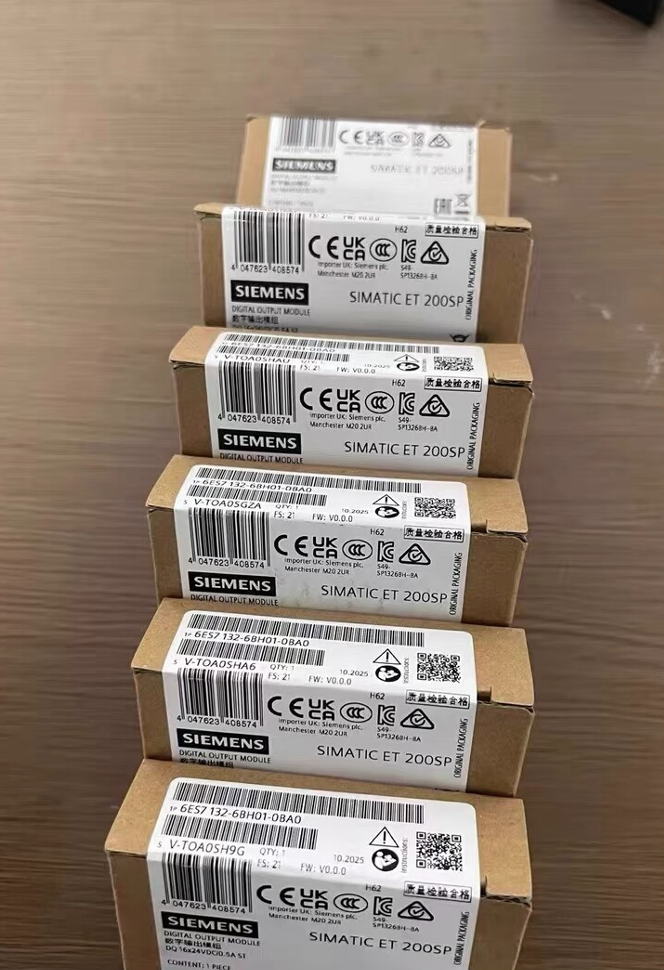

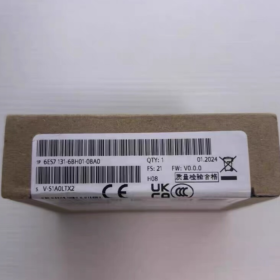
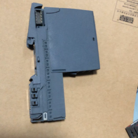
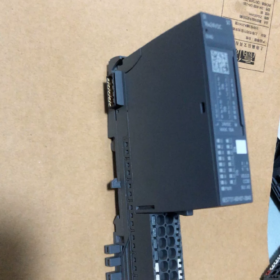
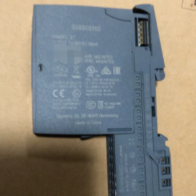
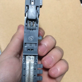
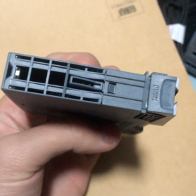
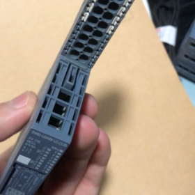
- Designazione completa del modello & Posizionamento
Simatic ET200SP DI 16×24VDC ST Modulo di ingresso digitale standard di Siemens
Serie: ET200SP Periferia decentrata (Stazione remota PROFINET/PROFIBUS)
Funzione: 16-canale 24 Ingresso digitale V CC per la raccolta di segnali da sensori PNP come interruttori, interruttori di prossimità, sensori fotoelettrici e finecorsa
Tipo di codifica: Codifica meccanica tipo A, compatibile solo con BaseUnit tipo A0
Scomposizione del codice modello
| Segmento di codice | Definizione |
| 6ES7131 | Ingresso digitale ET200SP (DI) Serie di moduli |
| 6BH01 | 16-canale 24 V DC Standard DI, Versione hardware V1 |
| 0BA0 | Versione industriale standard, nessun rivestimento anticorrosivo e nessun miglioramento della soppressione dei picchi |
- Specifiche elettriche principali
2.1 Alimentazione elettrica & Caratteristiche di ingresso
Fornitura nominale: 24 A DC, intervallo consentito 19.2 ~ 28.8 V, con protezione da inversione di polarità
Tipo di ingresso: Lettura P (Ingresso PNP in diminuzione, CEI 61131 Tipo 3)
Logica 0: -30 V~ +5 V
Logica 1: +11 V~ +30 V
Corrente tipica in stato attivo per canale: 2.5 mA; Corrente totale massima del modulo: 90 mA
Consumo energetico tipico: 1.7 W
Raggruppamento dei canali: Due gruppi (Canali 0~7 / 8~15). Tutti i sensori all'interno di un gruppo devono essere uniformemente PNP o NPN; è vietato il cablaggio misto.
2.2 Ritardo filtro (8 livelli configurabili in TIA Portal)
0.05 / 0.1 / 0.4 / 0.8 / 1.6 / 3.2 / 12.8 / 20 SM
Ulteriore ritardo del cavo di 30 ~ 500 μs. Per ambienti con forti interferenze da parte degli inverter si consiglia un'impostazione del filtro ≥ 3,2 ms.
2.3 Lunghezza massima del cavo
Cavo schermato: 1000 massimo
Cavo non schermato: 600 massimo
- Struttura meccanica & Installazione
- Dimensioni: 15 mm (W) × 73 mm (H) × 58 mm (D), design compatto ultrasottile
- Classe di protezione: IP20, Montaggio su guida DIN solo all'interno del quadro elettrico
- Temperatura ambiente
Montaggio orizzontale: 0 ~ +60 °C
Montaggio verticale: 0 ~ +40 °C
Magazzinaggio & Trasporti: -25 ~ +70 °C
- Indicatori: LED verde indipendente per ciascun canale (ACCESO = Logico 1, SPENTO = Logica 0); nessun LED di errore hardware dedicato
- Indirizzo Occupazione: Consuma 2 byte di input più uno aggiuntivo 2 byte per informazioni diagnostiche QI. Interruzione hardware, la modalità isocrona e le funzioni contatore non sono supportate.
- Schemi elettrici (BaseUnit tipo A0 Obbligatoria)
4.1 2-Contatti passivi a filo (Interruttori di limite, Pulsanti)
Cablare direttamente alla BaseUnit A0: un terminale di contatto si collega a DIx, l'altro a M (24 V negativo). Per il rilevamento della rottura del filo, collegare un 25 ~ 45 Resistenza da kΩ in parallelo al contatto.
4.2 3-sensori PNP a filo (Fotoelettrico comune / Interruttori di prossimità)
Terminale di distribuzione potenziale richiesto:
Filo marrone del sensore: L+ 24 V
Filo blu del sensore: Terra M comune
Filo nero del sensore (Segnale): Collegare al canale DI del modulo
> I sensori NPN non devono essere collegati direttamente a questo modulo; logica 1 i segnali non possono essere rilevati.
4.3 2-Sensori di prossimità induttivi a filo
Corrente massima a circuito chiuso limitata a 1.5 mA. I cavi lunghi possono attivare falsi allarmi di rottura filo.
- Funzioni diagnostiche & Limitazioni funzionali
- Supporta la diagnosi di rottura del filo (è necessario un resistore di rilevamento parallelo); diagnosi di cortocircuito non disponibile
- Nessuna protezione da sovracorrente a livello di canale; i cortocircuiti del sensore non attiveranno gli allarmi di guasto dei singoli canali
- Nessuna uscita di alimentazione encoder e nessun ausiliario 24 Alimentazione Vcc
- Supporta I&M0~I&Informazioni sul dispositivo M3; hardware riconosciuto automaticamente da TIA Portal
- Compatibilità di comunicazione: CPU S7-1200/1500, CPU ET200SP, PROFINET IO, PROFIBUS DP
- Confronto di derivati della stessa serie
| Numero di modello | Differenze | Applicazioni tipiche |
| 6ES7131-6BH01-0BA0 | DI base standard senza rivestimento anticorrosivo | Workshop generali, attrezzatura standard a temperatura normale |
| 6AG1131-6BH01-7BA0 | Rivestimento anticorrosivo SIPLUS, raggio d'azione -40 ~ +70 °C | Impianti chimici, porti, ambienti corrosivi ad alta umidità |
| 6ES7131-6BH01-0CA0 | Soppressione delle sovratensioni incorporata | Cavi di campo a lunga distanza, zone soggette a fulmini |
| 6ES7131-6BH00-0BA0 | Modello precedente obsoleto, completamente compatibile con l'hardware | Sostituzione di pezzi di ricambio per apparecchiature legacy |
- Scenari applicativi tipici
- Linee di assemblaggio automobilistiche: Raccolta del segnale per la conferma della posizione del dispositivo, cancelli di sicurezza e pulsantiere della postazione di lavoro
- Confezione & Attrezzature logistiche: Conteggio fotoelettrico, interruttori di rilevamento inceppamenti, ordinamento dei segnali di trigger
- Sistemi di trattamento dell'acqua: Interruttori di livello a galleggiante, finecorsa delle valvole, segnali di feedback del funzionamento della pompa
- Automazione delle macchine utensili: Travel limit switches, tool detection, safety circuit contacts
- Selezione del modello & Precauzioni operative
- Only Type A0 BaseUnit is permitted; Type B0/C0 and other coded base units are incompatible. The module features an integrated Type A coding lock to prevent incorrect insertion.
- All sensors within each 8-channel group must share the same polarity; PNP and NPN devices cannot be mixed in one group.
- Cables routed near inverters and servo drives must be shielded to eliminate false triggering.
- Increase input filter delay for long cables to suppress electromagnetic interference.
- No SIL safety certification. This module cannot be used independently for safety circuits; safety relays or safety I/O modules are required.
- Alternative Replacement Options
- Direct equivalent replacement: 6AG1131-6BH01-7BA0 (wide-temperature anti-corrosion version)
- Higher-density upgrade: 6ES7131-6BF01-0BA0 (8-modulo DI isolato a canale)
- Sostituzione dell'applicazione di sicurezza: 6ES7131-6FD01-0BB1 (Sicurezza DI, SIL 2 compiacente)
Principio di funzionamento completo del raggruppamento di canali per 6ES7131-6BH01-0BA0
- Definizione del gruppo hardware (Fisso 8 Canali per gruppo, 2 Totale gruppi)
IL 16 i canali di ingresso sono fisicamente divisi in due domini di potenziale di riferimento indipendenti con circuiti hardware interni completamente separati:
- Gruppo 1: Channels DI.0 ~ DI.7 (Primo 8 punti)
- Gruppo 2: Channels DI.8 ~ DI.15 (Scorso 8 punti)
Logica sottostante fondamentale: Riferimento comune indipendente M per gruppo
Il modulo assegna internamente a ciascun gruppo una terra di riferimento M separata, senza collegamento elettrico tra i due gruppi.
Tutti i canali all'interno di un gruppo condividono lo stesso potenziale del gruppo M. Tutto 8 i canali in un singolo gruppo devono utilizzare la stessa polarità del sensore (tutto PNP o tutto NPN); i due gruppi possono adottare polarità diverse.
- Funzionamento circuitale dei gruppi di canali
2.1 Modalità standard (Impostazioni di fabbrica: PNP / Lettura P in calo)
Struttura del circuito interno per ciascun gruppo:
Ogni canale DIx viene richiamato internamente 24 A DC
Condizione di conduzione del segnale: DIx collegato a 0 V (M) → Circuito chiuso, Il PLC rileva la logica 1
Compatibile con sensori PNP a 3 fili e contatti passivi a 2 fili (pulsanti / finecorsa)
Regole di cablaggio:
I terminali negativi di tutti i sensori del gruppo si collegano uniformemente al terminale M del gruppo
I sensori PNP e NPN non possono coesistere nello stesso gruppo; altrimenti i canali parziali rimangono permanentemente logici 0 o Logica 1.
2.2 Cablaggio di sensori NPN a un singolo gruppo (Uscita sorgente)
I sensori NPN emettono un livello basso 0 Segnali V che non possono essere riconosciuti per impostazione predefinita. Modificare la connessione M comune del gruppo a 24 VL+:
DIx riceve un livello alto 24 Segnale V dal sensore NPN per chiudere il circuito
Solo il potenziale comune del gruppo target necessita di aggiustamenti; l'altro gruppo rimane inalterato.
2.3 Principali caratteristiche di isolamento della separazione di gruppo
Nessun collegamento elettrico tra i due gruppi. È completamente consentito connettere il gruppo 1 M a 0 V e Gruppo 2 M a 24 VL+.
Cortocircuiti o guasti a terra su un gruppo non interferiranno con l'acquisizione del segnale sull'altro gruppo.
I sensori su cavi lunghi o circuiti di alimentazione separati possono essere messi a terra in gruppi separati per ridurre le interferenze del circuito di terra.
- Mappatura tra indirizzi I/O e gruppi di canali (Area di memoria del PLC)
IL 16 i canali occupano 2 byte di ingresso, rigorosamente assegnati per gruppo in corrispondenza uno a uno:
Gruppo 1 (DI.0~DI.7): "IBx" (1primo byte, bit0 ~ bit7)
Gruppo 2 (TU.8~TU.15): "IBx+1". (2secondo byte, bit0 ~ bit7)
Esempio: Indirizzo iniziale del modulo IB100
DI0~DI7 = I100.0 ~ I100.7
DI8~DI15 = I101.0 ~ I101.7
I dati sullo stato del QI diagnostico vengono caricati in due segmenti corrispondenti a ciascun gruppo.
- Disposizione dei terminali dei gruppi di canali corrispondenti della BaseUnit tipo A0
Logica di disposizione dei morsetti della BaseUnit A0 corrispondente:
- Terminali 1~8: DI.0~DI.7 (Gruppo 1) + Gruppo 1 Comune M
- Terminali 9~16: TU.8~TU.15 (Gruppo 2) + Gruppo 2 Comune M
L'unità base è dotata di due terminali M indipendenti fisicamente separati per il collegamento di potenziali diversi a ciascun gruppo.
- Tre scenari pratici tipici di cablaggio per il raggruppamento
Scenario 1: Tutto il cablaggio PNP (Più comune)
Gruppo 1 M e Gruppo 2 M in cortocircuito insieme a 0 V (24 V negativo)
Sensori PNP a 3 fili uniformi e interruttori passivi per entrambi i gruppi senza conflitti
Scenario 2: PNP di un gruppo, Un gruppo NPN (Consentito)
Gruppo 1 (DI0~7) M collegato a 0 V → Cablato con fotoelettrico PNP / sensori di prossimità
Gruppo 2 (DI8~15) M collegato a 24 V L+ → Cablato con sensori NPN
Questa configurazione è valida. I potenziali di gruppi indipendenti non interferiscono tra loro, e tutti i segnali vengono riconosciuti normalmente.
Scenario 3: PNP misto & NPN all'interno di un gruppo (Severamente proibito)
Esempio: DI0~4 cablato ai sensori PNP, DI5~7 cablato a sensori NPN
Il gruppo ha un solo potenziale M condiviso, creando conflitti circuitali con i seguenti fenomeni:
Canali parziali permanentemente senza segnale (Logica costante 0)
Falsi attivamenti casuali e sfarfallio del segnale
I casi più gravi causano un sovraccarico del circuito di ingresso e danni permanenti al canale del modulo
- Funzioni diagnostiche basate su gruppi
Il rilevamento della rottura del filo funziona in base al gruppo:
I resistori di rilevamento sono collegati in parallelo a tutti i canali in un gruppo; la diagnosi di rottura cavo viene abilitata/disabilitata per l'intero gruppo contemporaneamente
Un guasto di rottura conduttore rilevato in un gruppo attiva la diagnostica solo per quel gruppo, lasciando inalterato l'altro gruppo
I parametri di ritardo del filtro si applicano all'intero modulo; le impostazioni di filtro indipendenti per gruppo non sono supportate.
- Vantaggi ingegneristici della progettazione a doppio gruppo
- Compatibilità con doppio sensore: Cablaggio diretto per sensori PNP e NPN senza relè intermedi
- Isolamento di diverse spire potenziali: Separare i segnali delle macchine utensili ad alta e bassa potenza in due gruppi per mitigare le interferenze di modo comune
- Zonazione dei guasti: Cortocircuiti o guasti a terra su un gruppo non disabiliteranno tutti 16 canali
- Cablaggio flessibile: Ogni gruppo può essere alimentato da un indipendente 24 Alimentazione Vcc; i guasti di alimentazione su un alimentatore non influiscono sull'altro gruppo.
- Riepilogo veloce
- Hardware fissato in 2 gruppi di 8 canali ciascuno, con un riferimento comune indipendente M per ogni gruppo
- Tutti i sensori all'interno di un gruppo devono condividere la stessa polarità; i due gruppi possono utilizzare liberamente polarità diverse
- Assegnazione degli indirizzi, i dati diagnostici e i potenziali di riferimento comuni sono gestiti separatamente per gruppo
- Essenza fondamentale: I due gruppi presentano circuiti di ingresso elettricamente isolati e condividono solo l'alimentazione del modulo.





NH42-63-318x560.png "Commutatori automatici di tipo PC CHINT (ATS)NH42-63/4SZ")



