 コンタクタ,サーキットブレーカー,ソーラーインバーター,電気メーター,太陽電池

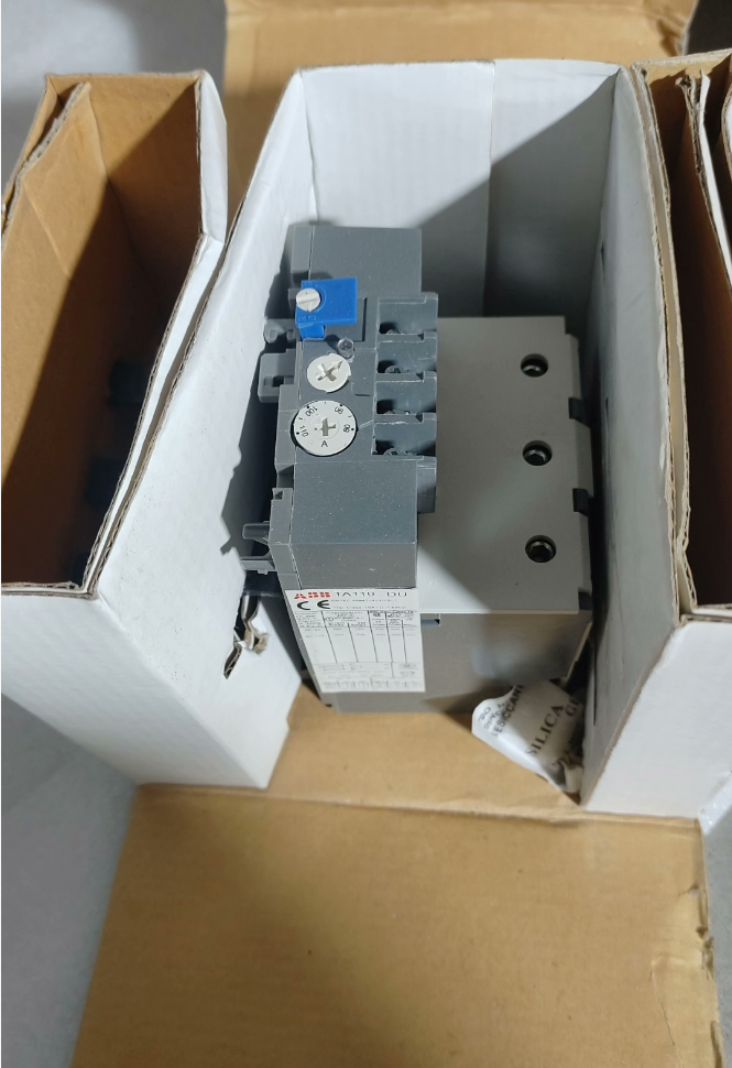

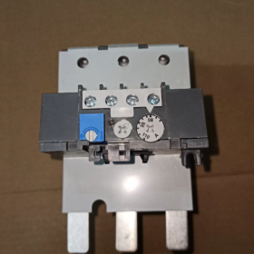
TA110DU110 は古典的な 3 極です サーマル過負荷リレー から ABB TAシリーズ, 定格電流範囲 80 ~ 110A の三相非同期モーターに統合保護を提供. バイメタルストリップの逆時間トリップ原理を採用, このリレーには、欠相保護と自動周囲温度補償が標準装備されています。, 旅行クラスがクラス10Aの場合. ABB A/AE/AF95~110シリーズコンタクタに直接接続することも、DINレールに独立して取り付けることもできます。. 切り替え可能な手動/自動リセットモードとノーマルオープンモードを1つ装備 (いいえ) プラスワンは通常休業 (ノースカロライナ州) 補助信号接点, 産業用モーター制御回路の標準保護部品として機能します。. ファンなどの電力負荷に広く適用されます。, ウォーターポンプ, コンプレッサーとコンベアライン, 過負荷によるモーターの巻線焼損事故を効果的に防止します。, ローターのロックと欠相.
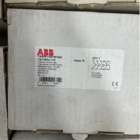
フルモデル: `TA110DU110`
- フェイシング: ABB サーマル過負荷リレーの一般的なシリーズ コード, 電熱保護リレーの代表製品
- 110: フレーム電流定格, この製品の最大定格フレーム電流 110A を示します。
- の: 関数タイプコード, 3極保護を備えた標準仕様を表します, 欠相検出, 周囲温度補償とコンタクタへの直接取り付け
- 110: 現在の設定値の上限, 80A~110Aの調整可能な電流範囲に対応
主要な技術仕様
| パラメータのカテゴリ | パラメータ項目 | 詳細仕様 |
| 主回路特性 | 定格絶縁電圧 Ui | 690Vと / 440ワシントンDCで |
| UL/CSA 定格動作電圧 | 600Vと | |
| 調整可能な電流範囲 | 80A~110Aまで連続調整可能 | |
| 旅行クラス | クラス10A (標準モーター保護クラス) | |
| 極数 | 3 極, 完全な 3 極保護 | |
| 欠相保護 | 標準内蔵; 三相不平衡時のトリップを加速します。 | |
| 温度補償 | サポートされています; 保護精度は周囲温度-25℃~+55℃の範囲内でも影響を受けません。 | |
| 補助接点 | 接点構成 | 1 いいえ + 1 ノースカロライナ州, 電気的に絶縁された |
| 従来の熱電流 Ith | 5あ | |
| 定格接点容量 | AC250V 3A; DC24V 5A | |
| 機械式 & 取り付け | 取付方法 | コンタクタへの直接取り付け / 独立DINレール取付 |
| 互換性のあるコンタクタ | A95シリーズ, A110, AE95, AE110, AF95, AF110 | |
| 配線方法 | ネジ締め端子 | |
| 全体の重量 | 約. 0.76kg | |
| リセットモード | 手動/自動リセット切替可能; リモートリセット拡張をサポート | |
| 環境 & 認証 | 動作周囲温度 | -25℃~+55℃ |
| 保管温度 | -40℃~+70℃ | |
| 侵入保護評価 | IP20 | |
| コンプライアンス認証 | CE, UL, CSA, CCC, GL (ドイツロイド船級認定) | |
| 準拠規格 | IEC 60947-4-1, で 60947-4-1 |
同一シリーズ内のモデルの相互参照
- TA110DU フレームの全仕様
| フルモデル | 調整可能な電流範囲 | 対応モーター出力 (380V) | 適合コンタクタ |
| TA110DU-65 | 50 ~65A | 30kW | A95/AE95/AF95 |
| TA110DU-80 | 60 ~80A | 37kW | A95/AE95/AF95 |
| TA110DU-90 | 66 ~90A | 45kW | A110/AE110/AF110 |
| TA110DU-110 | 80 ~110A | 55kW | A110/AE110/AF110 |
- 隣接するフレームシリーズの比較
| シリーズモデル | フレーム定格電流 | 最大調整可能電流 | 該当するシナリオ |
| TA110DU | 110あ | 110あ | 中くらい & 小出力モーター (30~55kW) |
| TA200DU | 200あ | 200あ | 中くらい & 大出力モーター (75~110kW) |
| TA450DU | 450あ | 450あ | ハイパワーヘビーデューティーモーター (132~250kW) |
典型的なアプリケーションシナリオ
- 標準モータースターター保護回路: ABB A/AF シリーズコンタクタと組み合わせて電磁スタータを形成, 三相モーターの主回路に直列に接続し、モーターの過負荷に対する保護を実現します。, ローターのロックと欠相. ファンを含む一般電源機器の標準保護ソリューションです。, ウォーターポンプ, エアコンプレッサーおよび工作機械スピンドル.
- MCC モーター コントロール センター: 引き出しキャビネットおよび固定キャビネット内のモーターフィーダ回路の標準保護ユニットとして機能します, コンタクタと統合され、統合されたモータの始動/停止制御と保護を実現します。.
- コンベア & 物流仕分けシステム: ローラーモーターや仕分け駆動モーターとの組み合わせ, 生産ラインの頻繁な発停や負荷変動の労働条件に適応, 長期間の過負荷によるモーターの劣化や焼損を防止します。.
- セントラル空調 & 冷凍ユニット: コンプレッサーや冷却塔ファンなどの冷凍電源機器を保護します。, 負荷変動が激しく、季節による高負荷運転という冷凍業界の特性に適しています。.
- OEM一式機器のサポート: 包装機械をはじめとする産業機械に幅広くマッチします。, ゴム & プラスチック機械および冶金補助装置. モータ保護部品の標準化として, 機器の工場出荷時の電気安全仕様要件を満たしています.
一般的なトラブルシューティング マトリックス
| 故障現象 | 根本原因の分析 | 段階的な解決策 |
| モーターの通常動作中にリレーが誤ってトリップする | 1. 低電流設定値, モーター定格電流より低い | 1. モーターの定格電流を確認し、設定ノブを対応する定格値に調整します。 |
| 2. 周囲温度が高すぎて補償範囲を超えた場合 | 2. キャビネットの熱放散を改善し、直射日光や熱源の放射を避けます。 | |
| 3. 三相電圧の不平衡によって引き起こされる重大な電流偏差 | 3. 三相電流を測定して、電圧不均衡や欠相の隠れたリスクをトラブルシューティングします。 | |
| 4. クラスの耐用限界を超えるモーター起動時間が長すぎる 10 旅行クラス | 4. クラスのサーマルリレーに置き換えてください 20 またはクラス 30 高負荷の起動アプリケーション向け | |
| モーターの過負荷またはローターのロックによりリレーがトリップしない | 1. 電流設定値が高すぎる, モーターの定格電流をはるかに上回る | 1. モーターの定格電流と厳密に一致するように設定値を再校正します。 |
| 2. 主回路配線端子の緩みによる接触抵抗過大 | 2. 主回路端子の締め付けと過熱のトラブルシューティング & 酸化の問題 | |
| 3. リレーの機械機構の固着とトリップアセンブリの故障 | 3. 電源を遮断し、トリップ機構の柔軟性を手動でテストします。; 詰まりが発生した場合はモジュールを交換してください | |
| 欠相故障時に保護が作動しない | 1. 三相受電配線が間違っており、リレー主回路との接続が不完全である | 1. L1/L2/L3 の三相配線を検証して、すべての相が確実に接続されていることを確認します。 |
| 2. 内部バイメタル部品の経年劣化と故障 | 2. 欠相を人工的にシミュレートして保護機能をテスト; 機能が故障した場合はリレーを交換してください | |
| 補助接点信号の異常または出力なし | 1. 補助接点負荷が定格容量を超えている, 接点焼損の原因となります | 1. 負荷電流が接点定格を超えていないことを確認してください; 必要に応じて電流増幅用の中間リレーを追加します。 |
| 2. トリップ後のリセットなし, 接点は故障状態のままです | 2. 根本的な障害の原因をトラブルシューティングした後、リレーを手動または自動でリセットします。 | |
| 3. 接点酸化による接触不良 | 3. 接点のオンオフ抵抗を測定する; 接触不良がある場合はモジュールを交換してください |
- 端子の定義 & 機能の説明
TA110DU110 は業界標準の端子番号規則を採用しています。, 2つの部分に分かれています: 主電源回路と補助制御回路. すべての端子が前面に取り付けられたネジクランプ式で、すべての配線作業が前面からアクセス可能です。.
- 主回路端子 (三相電源回路)
| 端子マーク | 端子の種類 | 配線説明書 |
| 1L1, 3L2, 5L3 | 着信端末 | 上側入力, コンタクタ主接点の出力端子に接続, 三相電源L1/L2/L3に対応 |
| 2T1, 4T2, 6T3 | 発信端末 | 下側出力, 三相非同期モーターの固定子巻線に直接接続 |
注意事項: 三相主回路には極性の制限はありません, ただし、各相は相間の誤接続なしに 1 対 1 対応で接続する必要があります。. コンタクタに直接取り付ける場合, 主回路はプラグイン銅バーを介して自動的に導通され、追加の電源配線は必要ありません。.
- 補助回路端子 (コントロール & 信号回路)
| 端子マーク | 接点の種類 | 機能の説明 | 一般的な配線目的 |
| 95 – 96 | 通常閉 (ノースカロライナ州) | 通常の動作条件下では導電性; 過負荷・欠相によるトリップ時に開放 | コンタクタコイル制御回路に直列に接続され、故障時にコンタクタへの電力供給を遮断し、モータを停止します。 |
| 97 – 98 | 通常開 (いいえ) | 通常の動作条件下では切断される; 過負荷・欠相によるトリップ時に閉止 | 音光警報回路またはPLCデジタル入力ポイントに接続して、障害信号のアップロードと警報通知を行います。 |
補助接点は電気的に絶縁されており、主回路には電気的に接続されておらず、従来の熱電流は 5A です。. 大電力負荷制御時の容量拡大と接点焼損防止のため、直列接続には中間リレーを推奨します。.
- 一般的な配線方式
- コンタクタへの直接取り付け配線 (最も一般的に使用される)
TA110DU110の標準的な塗布方法です。. ABB A95/A110/AF95/AF110 シリーズ コンタクタの上部に直接接続されます。. 主回路は内部プラグインコネクタを介して自動的に接続されます, 制御回路のみで外部配線が不要:
- 三相電力は回路ブレーカーを通過し、コンタクタの主入力端子 L1/L2/L3 に接続されます。
- サーマルリレーをコンタクタに直接取り付けた後, 主回路は余分な電源配線なしで自動的に導通します。
- 制御電源の一端はストップボタンとスタートボタンを通過し、コンタクタコイル端子A1に接続します。
- の 95-96 サーマルリレーのNC接点はコンタクタコイル回路の活線に直列に接続されており、過負荷時のモータの自動停止を実現します。
- の 97-98 サーマルリレーの NO 接点は、故障表示灯と並列に接続されるか、故障警報用に PLC DI ポイントに接続されます。
- 独立したDINレール取付配線
独立したレールマウントを採用し、別の設置や他社製コンタクタとの組み合わせが可能:
- コンタクタ出力端子 L1/L2/L3 は電源ケーブルを介してサーマルリレー入力端子 1L1/3L2/5L3 に接続されています。
- サーマルリレー出力端子2T1/4T2/6T3はモーターの三相端子に接続
- The control circuit follows the same wiring logic as the direct mounting scheme, と 95-96 NC contact wired in series into the contactor coil circuit
配線上の注意:
The cross-sectional area of main circuit cables shall match the 110A rated current; 25mm² copper cables are recommended
1~1.5mm² control cables are suggested for auxiliary control circuits
Reliable earthing is mandatory to guarantee personal and equipment safety
Ⅲ. Parameter Comparison Table of Cross-Brand Equivalent Models
Below is a parameter comparison of mainstream thermal overload relays of the same current range from Siemens and Schneider Electric, for reference during alternative selection:
| 比較項目 | ABB | シュナイダーエレクトリック | シーメンス |
| フルモデル | TA110DU110 | LRD3365C | 3RU5146-4MB1 |
| 調整可能な電流範囲 | 80 ~110A | 80 ~ 104A | 80 ~ 100A |
| フレーム定格電流 | 110あ | 115あ | 140あ |
| 旅行クラス | クラス10A | クラス 10 | クラス 10 |
| 極数 | 3 極 | 3 極 | 3 極 |
| 補助接点構成 | 1いいえ + 1ノースカロライナ州 (電気的に絶縁された) | 1いいえ + 1ノースカロライナ州 (電気的に絶縁された) | 1いいえ + 1ノースカロライナ州 (電気的に絶縁された) |
| 欠相保護 | 標準内蔵 | 標準内蔵 | 標準内蔵 |
| 周囲温度補償 | サポートされています (-25℃~+55℃) | サポートされています (-20℃~+60℃) | サポートされています (-20℃~+60℃) |
| リセットモード | Switchable manual/automatic | Switchable manual/automatic | Switchable manual/automatic |
| Compatible Contactor Series | A95~A110, AF95~AF110 | LC1D95~LC1D115 | 3RT5045~3RT5046 |
| 取付方法 | Direct mounting on contactor / DINレール | Direct mounting on contactor / DINレール | Direct mounting on contactor / DINレール |
| コンプライアンス認証 | CE, UL, CCC, GL | CE, UL, CCC | CE, UL, CCC |


 インパルスヒートシール温度調節器")


")


NH42-63-318x560.png "CHINT PC型自動切替スイッチ (ATS)NH42-63/4SZ")


