 コンタクタ,サーキットブレーカー,ソーラーインバーター,電気メーター,太陽電池

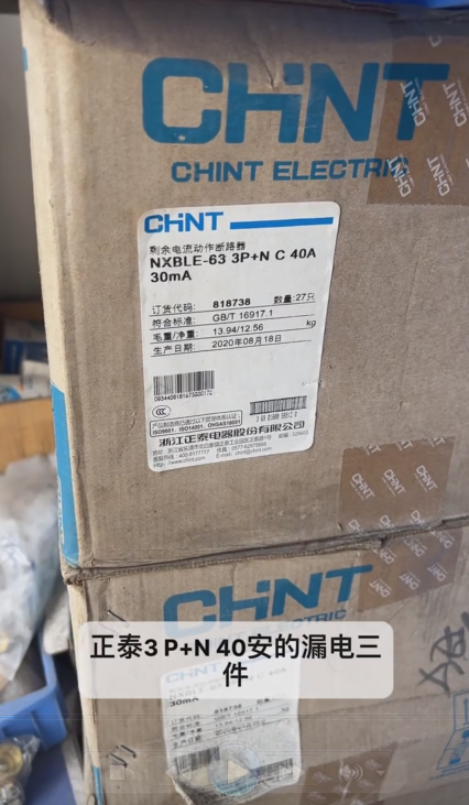
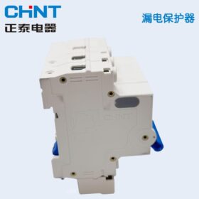

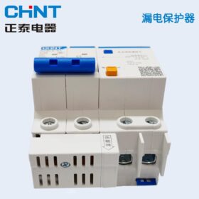
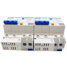

Chint NXBLE-63 3P+N C40A 残留電流作動型サーキットブレーカー
Chint NXBLE-63 3P+N C40A is a residual current operated circuit breaker, mainly used for overload, short-circuit and leakage protection of electrical circuits.
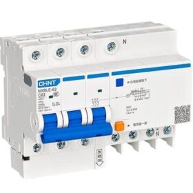
– 極数: 3P+N, namely three poles plus neutral wire, which can control three phase wires and one neutral wire simultaneously.
– 定格電流: 40あ, indicating that the maximum current the circuit breaker can carry for long-term stable operation is 40A.
– Residual Current: Usually 30mA. When the leakage current in the circuit reaches or exceeds this value, the circuit breaker will trip automatically.
– 遮断容量: 6の, meaning it can quickly cut off the circuit when the short-circuit current reaches 6kA, thus protecting the safety of equipment and personnel.
– Leakage Protection Type: Type AC, suitable for leakage protection in alternating current circuits.
– Residual Current Release Type: Electronic type, which detects leakage signals through electronic components and triggers the tripping mechanism.
– 定格電圧: 400VAC, applicable to AC circuits with a rated voltage of 400V.
– 機能的な特徴: It has overload, short-circuit and residual current operation protection functions. It complies with standards such as GB/T 16917.1 およびIEC 61009-1, and has obtained CCC certification, which can effectively ensure circuit safety.
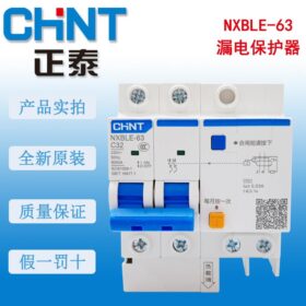
– Appearance and Installation: It features a white plastic shell and a blue operating handle, with a compact size. It can be installed on standard guide rails, facilitating installation and wiring in distribution boxes.
Installation and Operation Instructions for Chint NXBLE-63 3P+N C40A Residual Current Operated Circuit Breaker
Chint NXBLE-63 3P+N C40A is an electronic residual current operated circuit breaker, integrating triple protection functions of overload, short-circuit and leakage protection. It is suitable for 400VAC three-phase four-wire distribution circuits. The following are standardized specifications for installation, wiring, operation and maintenance.
- インストール前の準備
- Check Product Status
Confirm that the circuit breaker model is NXBLE-63 3P+N C40A, and verify that the nameplate parameters (rated voltage 400VAC, rated current 40A, rated residual operating current 30mA, breaking capacity 6kA) match the application scenario.
Check that the shell is free from damage, 操作ハンドルは柔軟です (with clear “ON”, “OFF” そして “テスト” marks), and the wiring terminals are free from oxidation.
Verify the CCC certification mark to ensure the product is genuine.
- Confirm Installation Environment
周囲温度: -5℃~+40℃, with the average temperature not exceeding +35℃ within 24 時間.
高度: ≤2000m; derating is required if the altitude exceeds this limit.
Humidity requirement: Relative air humidity ≤90% (at 25℃), free from condensation, corrosive gases and dust accumulation.
Installation location: Avoid severe vibration, direct sunlight and stay away from strong magnetic field interference sources.
- Prepare Tools and Accessories
ツール: Phillips screwdriver, wire stripper, トルクレンチ, voltage tester pen.
Accessories: Standard 35mm DIN guide rail (the circuit breaker is equipped with guide rail mounting clips as standard), copper wiring terminals (it is recommended to use those suitable for 10-25mm² wires).
- Installation and Wiring Steps
- Guide Rail Installation
– This circuit breaker adopts 35mm DIN standard guide rail clamping installation, requiring no additional fixing screws.
– Operation method: Align the clamping clips on the back of the circuit breaker with the guide rail, press down and push forward until the clamping clips are fully locked on the guide rail; press the clip release button to remove the circuit breaker during disassembly.
– Installation spacing: Reserve a space of ≥5mm on both sides of the circuit breaker to ensure heat dissipation and wiring operation.
- 配線仕様 (Core Focus)
The neutral pole (N pole) of NXBLE-63 3P+N cannot be disconnected. During wiring, strictly distinguish between phase wire and neutral wire terminals, and reverse connection is strictly prohibited.
| Terminal Mark | Wiring Type | Conductor Specification (Copper Core) | Tightening Torque |
| L1/L2/L3 | Three-phase Phase Wires | 10-25mm | 2.5-3N*メートル |
| N | Neutral Wire | 10-25mm | 2.5-3N*メートル |
| Load-side Terminals | Outlet Circuit | Same as Inlet Specification | Same as Inlet Torque |
– Wiring Steps
- Power-off and Voltage Testing: Ensure that there is no voltage in the incoming circuit to avoid live wiring.
- Wire Stripping: Strip about 8-10mm of the wire insulation layer to expose the copper core without oxidation; it is recommended to install cold-pressed terminals to prevent wire loosening.
- Inlet Direction: Top-in and bottom-out (recommended) or bottom-in and top-out are both acceptable, but the wiring direction must be unified in the same power distribution system.
- Terminal Tightening: Tighten the wiring terminal screws with a screwdriver to ensure the wires are not loose; check the torque with a torque wrench to prevent over-loosening (which may cause heating) or over-tightening (which may damage the terminals).
- Neutral Wire Notes: The N pole must be connected to the neutral wire and cannot be left unconnected; it is strictly prohibited to connect phase wires to the N terminal, otherwise the leakage protection function will fail.
– Prohibited Operations
– It is strictly prohibited to use the 3P+N circuit breaker in three-phase three-wire circuits (scenarios without neutral wire).
– It is strictly prohibited to connect multiple strands of wires to the terminals (without installing terminal blocks).
– It is strictly prohibited to share the neutral wire on the outlet side of the residual current circuit breaker with neutral wires of other circuits.
Ⅲ. 操作方法
- Closing and Opening Operations
– Closing: Flip the operating handle upward to the “ON” position to put the circuit breaker into operation; if the handle is in the middle position (tripped state), flip it downward to the “OFF” position first, then flip it upward to close the circuit breaker.
– Opening: Flip the handle downward to the “OFF” position to manually cut off the circuit.
– Leakage Test: After closing the circuit breaker, press the “テスト” button on the panel; the circuit breaker should trip immediately (the handle bounces to the middle position), indicating that the leakage protection function is normal; it is recommended to perform the test once a month.
- Trip Fault Troubleshooting
After the circuit breaker trips, troubleshoot the cause before closing it again; do not close it blindly.
| Trip Phenomenon | 考えられる原因 | トラブルシューティング方法 |
| Trips when the TEST button is pressed | Normal leakage protection test | Close the circuit breaker directly |
| Trips immediately after closing | 1. Leakage in the line or load | 1. Test the line insulation resistance with a megohmmeter |
| 2. Reverse connection of phase wire and neutral wire | 2. Verify the marks of the wiring terminals | |
| 3. Repeated grounding of the neutral wire | 3. Remove redundant grounding points of the neutral wire | |
| Trips during load operation | 1. Load current exceeds 40A (過負荷) | 1. Reduce the load or replace the circuit breaker with a larger rated current |
| 2. Line short circuit | 2. Troubleshoot the short-circuit point (例えば, damaged wire insulation) | |
| 3. Excessive leakage current | 3. Test the leakage status of the equipment |
- Daily Operation Notes
– After the circuit breaker trips, eliminate the fault before closing it again to avoid expanding the fault due to repeated closing.
– It is forbidden to connect other electrical components (such as fuses) in parallel or series with the circuit breaker terminals.
– Do not connect equipment with large harmonics (such as frequency converters and electric welders) to the load side; さもないと, a Type A residual current circuit breaker should be selected.
- Maintenance and Upkeep
- Regular Inspection
毎月: Press the TEST button to test the leakage protection function to ensure reliable operation.
Quarterly: Clean the dust on the surface of the circuit breaker, and check whether the wiring terminals have heating discoloration or loose screws.
Annually: Test the insulation resistance between the incoming and outgoing lines of the circuit breaker with a megohmmeter (disconnect all loads; the insulation resistance ≥1MΩ is qualified).
- Fault Handling
If the circuit breaker does not trip when the TEST button is pressed, it indicates that the leakage protection function has failed; replace the circuit breaker immediately and do not continue to use it.
If the shell is cracked or the terminals are ablated, replace the product in a timely manner; do not reuse it after repair.
- Safety Warnings
- インストール, wiring and maintenance must be operated by certified electricians, and the power-off, voltage testing, grounding and tagging system must be strictly followed.
- Before putting the circuit breaker into operation, confirm that all loads are disconnected to avoid arc generation caused by closing with load.
- The residual current operated circuit breaker cannot replace grounding protection; the power distribution system must meet the grounding specification requirements at the same time.


")

NH42-63-318x560.png "CHINT PC型自動切替スイッチ (ATS)NH42-63/4SZ")


