 コンタクタ,サーキットブレーカー,ソーラーインバーター,電気メーター,太陽電池


- モデルの解釈
| モデルセグメント | 説明 |
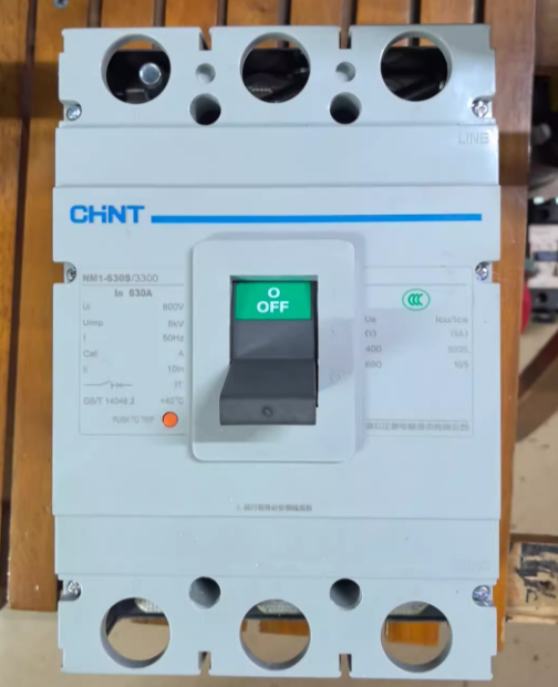
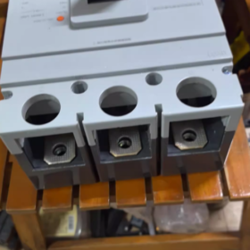
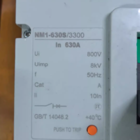
| NM1 | 製品シリーズコード; CHINT Electric NM1 series molded case circuit breaker, suitable for power distribution protection and motor protection scenarios |
| 630 | Frame size rated current; the maximum current rating that this series of circuit breakers can carry is 630A |
| S | 遮断容量クラス; Type S indicates standard breaking capacity, usually 35kA (refer to the product manual for details), suitable for conventional power distribution environments. Other classes in the same series include H (より高い遮断容量) and L (lower breaking capacity) |
| 3300 | 極数 + trip unit type + accessory code |
| First two digits “33”: 3-ポールサーキットブレーカー, suitable for three-phase three-wire power distribution systems | |
| Last two digits “00”: 付属品なし (補助接点など, 不足電圧解除, シャントリリース, 等) | |
| 630あ | 定格電流; the rated operating current set for this circuit breaker is 630A |
- コア技術パラメータ
| パラメータのカテゴリ | 特定のインデックス |
| 定格動作電圧 (うえ) | Three-phase AC 400V (50Hz), 低電圧配電システムに最適 |
| 定格電流 (で) | 630あ |
| フレーム電流 (イウ) | 630あ |
| 遮断容量 (ICU) | クラスS: 35の (at AC 400V) |
| トリップユニットの種類 | 熱磁気トリップユニット (overload long-time delay protection + 短絡瞬時保護) |
| Overload Protection Characteristics | Long-time delay inverse-time characteristic; setting current Ir = 1.0In (630あ). It can withstand 1.05In for long-term operation and will not trip within 1 hour under 1.3In |
| Short-Circuit Protection Characteristics | Instantaneous trip setting current Ii = 10In (6300あ); it trips instantaneously when the short-circuit current reaches this value |
| 保護クラス | IP20 (enclosure protection, preventing finger access) |
| 取付方法 | Fixed type/draw-out type (confirm specific model; fixed type is standard) |
| 配線方法 | フロントパネル配線 (標準); rear-panel wiring is optional |
Ⅲ. 機能的な特徴
- Dual Protection Function: Integrates overload long-time delay protection and short-circuit instantaneous protection, which can effectively cut off overload and short-circuit fault currents to protect power distribution lines and equipment.
- 標準遮断容量: The 35kA breaking capacity meets the short-circuit protection requirements of most industrial plants, 商業ビル, and civil power distribution scenarios.
- モジュラー設計: Supports the installation of accessories such as auxiliary contacts, シャントリリース, and undervoltage releases to expand functions like remote control and fault signal feedback.
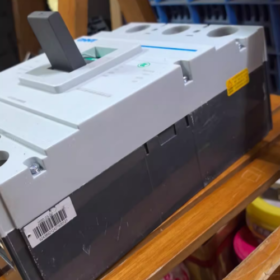
- 簡単操作: Adopts a manual energy storage operating mechanism with clear closing/opening actions, and is equipped with a transparent observation window for intuitive inspection of contact status.
- Long Electrical and Mechanical Service Life: Electrical service life ≥ 10,000 回; mechanical service life ≥ 20,000 回, suitable for power distribution scenarios with frequent switching.
- 適用範囲
- Main Switch of Power Distribution System: Suitable for incoming line and bus section switches in 400V three-phase low-voltage power distribution systems, protecting the secondary side of transformers and outgoing circuits of power distribution cabinets.
- Industrial Equipment Protection: Can be used as the power-side protection switch for high-power motors (ファンなどの, ウォーターポンプ, compressors with power ≤ 315kW).
- Building Power Distribution Scenarios: Protection of power distribution trunk lines in shopping malls, オフィスビル, factory workshops, 等, suitable for environments with conventional short-circuit current levels.
- に適さない: Power distribution systems with high short-circuit current (> 35の), precision equipment circuits requiring selective protection, and DC power distribution scenarios.
- 選択の提案
- Match Load Current: The rated load current should be ≤ 630A. If the load is a motor, the motor starting current must be considered (it is recommended that the instantaneous setting current of the trip unit be ≥ 8 モーター定格電流の倍).
- Verify Breaking Capacity: The calculated on-site short-circuit current should be ≤ 35kA. If the short-circuit current exceeds 35kA, upgrade to the NM1-630H type (より高い遮断容量, usually 50kA/65kA).
- アクセサリの選択:
For remote opening: Install a shunt release (コード 3310).
For undervoltage protection: Install an undervoltage release (コード 3320).
For fault signal feedback: Install auxiliary contacts (コード 3308).
- ブランド交換のリファレンス:
| ブランド | 代替機種 | 主要な相違点 |
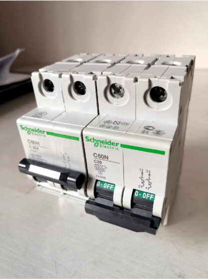
| シュナイダー | NSX630N 3P 630A | より高い遮断容量 (50の) and higher price |
| シーメンス | 3VL630 3P 630A | Richer modular accessories, suitable for Siemens power distribution systems |
| 美味しい | CDM1-630S 3300 630あ | Domestic brand of the same grade with consistent parameters and high cost performance |
- トラブルシューティング
| 一般的な障害 | 考えられる原因 | ソリューション |
| 閉店直後の旅行 | 1. Short-circuit fault exists in the line | 1. Troubleshoot the short-circuit point of the line and close after repair |
| 2. Leakage on the load side (not applicable if no leakage accessory is installed) | 2. Check the insulation condition of the load | |
| 3. The instantaneous trip current setting is too small | 3. Confirm whether the trip unit setting current matches the load | |
| Does not trip during overload | 1. Thermal trip unit failure | 1. Replace the thermal trip unit |
| 2. The trip unit setting current is adjusted too high | 2. Re-adjust the setting current to the rated value | |
| 3. Circuit breaker contact adhesion | 3. Disassemble and inspect the contacts; 必要に応じてサーキットブレーカーを交換します | |
| 閉められない | 1. Undervoltage release is not powered on (if installed) | 1. Check whether the power supply of the undervoltage release is normal |
| 2. 機械機構の詰まり | 2. Manually reset the mechanical mechanism and clean internal foreign objects | |
| 3. Line fault not eliminated | 3. Troubleshoot and eliminate line faults | |
| Abnormal heating during operation | 1. Loose wiring terminals | 1. Tighten the wiring terminals and apply conductive paste |
| 2. 負荷電流が定格値を超えている | 2. Reduce the load or replace with a larger specification circuit breaker | |
| 3. 周囲温度が高すぎる | 3. Improve ventilation and heat dissipation conditions |
Ⅶ. インストールとメンテナンスに関する注意事項
- 設置前, confirm that the rated voltage and current of the circuit breaker match the on-site power distribution system, and check that the appearance is intact and the mechanism is free of jamming.
- Ensure that the terminals are tightened during wiring to avoid heating caused by poor contact. For front-panel wiring, the wire cross-section should match the 630A current (it is recommended to use 240mm² copper core cable).
- Regularly (毎 6 月) inspect the contact status of the circuit breaker and the flexibility of the mechanical mechanism, and remove dust inside the enclosure.
- 故障トリップ後, the cause of the fault must be investigated first; do not close forcibly to avoid expanding the fault range.
Parameter Comparison Table of NM1-630S-3300 Series (400A/500A/630A)
| パラメータのカテゴリ | Model Specification | ||
| 基本パラメータ | NM1-630S-3300-400A | NM1-630S-3300-500A | NM1-630S-3300-630A |
| Frame Size Rated Current (イウ) | 630あ | 630あ | 630あ |
| 定格動作電流 (で) | 400あ | 500あ | 630あ |
| 定格動作電圧 (うえ) | AC 400V 50Hz | AC 400V 50Hz | AC 400V 50Hz |
| 極数 | 3-ポール | 3-ポール | 3-ポール |
| トリップユニットの種類 | 熱磁気 (過負荷による長時間遅延 + 瞬間短絡) | 熱磁気 (過負荷による長時間遅延 + 瞬間短絡) | 熱磁気 (過負荷による長時間遅延 + 瞬間短絡) |
| 保護特性 | |||
| 遮断容量 (ICU, AC400V) | 35の | 35の | 35の |
| Overload Long-Time Delay Setting Current (そして) | 400あ (1.0で) | 500あ (1.0で) | 630あ (1.0で) |
| Overload Withstand Characteristics | Withstand 1.05In for long-term operation; no tripping within 1h under 1.3In | Withstand 1.05In for long-term operation; no tripping within 1h under 1.3In | Withstand 1.05In for long-term operation; no tripping within 1h under 1.3In |
| Short-Circuit Instantaneous Setting Current (いい) | 10In = 4000A | 10In = 5000A | 10In = 6300A |
| 設置と配線 | |||
| 保護クラス | IP20 | IP20 | IP20 |
| 取付方法 | Fixed type/draw-out type (オプション) | Fixed type/draw-out type (オプション) | Fixed type/draw-out type (オプション) |
| Recommended Matching Copper Core Cable Cross-Section | 185mm² | 240mm² | 240mm²/300mm² |
| 機械的および電気的耐用年数 | |||
| 機械的寿命 | ≥20,000 times | ≥20,000 times | ≥20,000 times |
| 電気的寿命 | ≧10,000回 | ≧10,000回 | ≧10,000回 |
| 典型的なアプリケーションシナリオ | 1. Power-side protection for 185kW three-phase motors | 1. Power-side protection for 250kW three-phase motors | 1. Power-side protection for 315kW three-phase motors |
| 2. Power distribution branch switch (load current 350-400A) | 2. Power distribution trunk branch switch (load current 450-500A) | 2. Power distribution incoming line/bus section switch | |
| 3. Power distribution branch in small and medium-sized plants | 3. Power distribution branch in shopping malls and office buildings | 3. Power distribution trunk in large plants and high-rise buildings | |
補足的な選択のヒント
- All specifications of this series have the same breaking capacity. Select the corresponding specification only according to the rated load current; there is no need to verify the breaking capacity additionally.
- If the load is a motor with frequent starting, it is recommended to select a specification with a rated current 1.1-1.2 times that of the motor to avoid overload false tripping.
- For the same frame size specification, the rated current can be adjusted by replacing the trip unit without replacing the circuit breaker body, reducing the later transformation cost.


 シュナイダー TeSys GV2 シリーズより. 24~32Aの調整可能な電流設定が特徴です。,")


")
NH42-63-318x560.png "CHINT PC型自動切替スイッチ (ATS)NH42-63/4SZ")


