 コンタクタ,サーキットブレーカー,センサー,エンコーダ,PLC,コンバータ

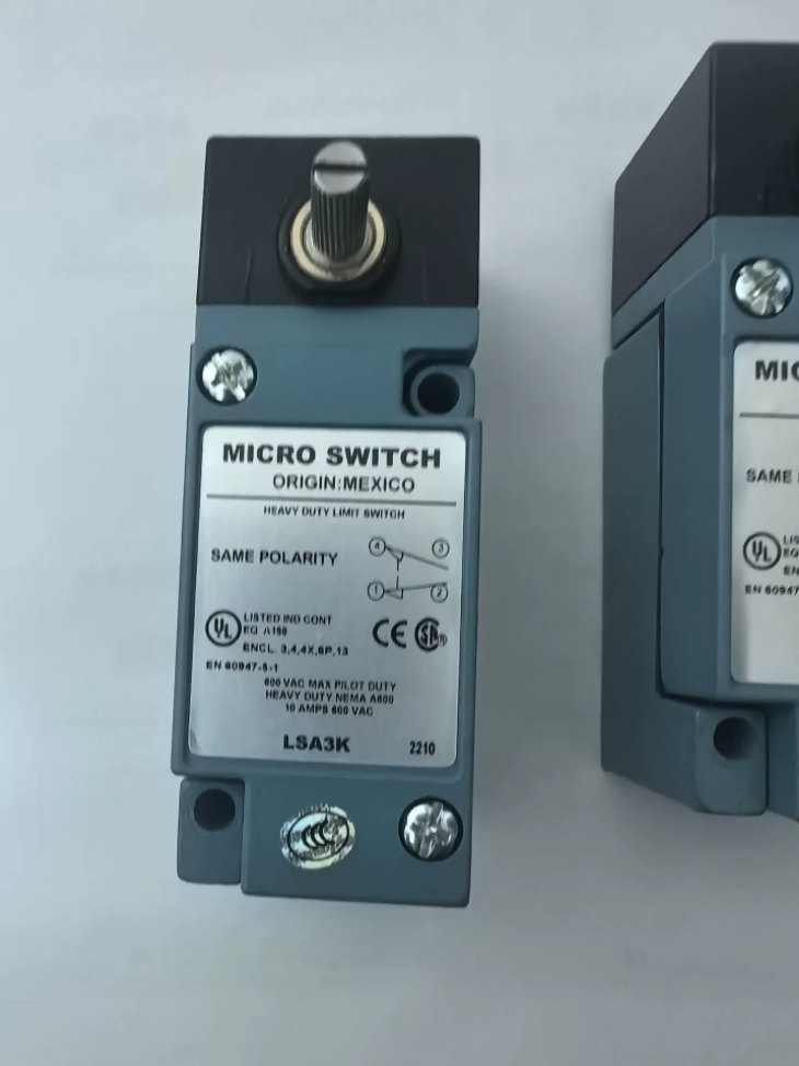

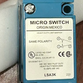
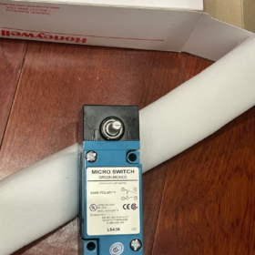
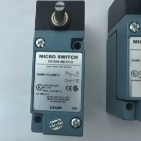
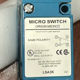
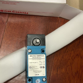
(HDLS Series Heavy-Duty Side-Rotary リミットスイッチ, also referred to as Micro LSA3K)
モデルの解釈
LSA3K: HDLS heavy-duty limit switch, non-plug-in body, side-rotary actuator head, SPDT (単極双投), screw-terminal wiring, NPT1/2 conduit port
ブランド: ハネウェル MICRO SWITCH, Made in USA
コアの電気仕様
| アイテム | 仕様 |
| 接点構成 | SPDT 1NO+1NC, double‑break snap‑action contacts |
| 定格電流 | 10 あ |
| マックス. AC Voltage | 600 VAC |
| マックス. DC Voltage | 250 VDC |
| 終了 | ネジ端子 (non‑plug‑in) |
| 動作モード | 瞬間的; actuable by clockwise / counter‑clockwise rotation |
機械式 & 環境仕様
アクチュエーター: Side-rotary shaft, マックス. operating torque 0.45 N·m (4 in-lb)
Pre-travel: マックス. 15°; Overtravel: 分. 60°
動作温度: -12℃ ~ +121℃
NEMA Ratings: 1, 3, 4, 4×, 6, 6P, 12, 13 (アウトドア, dust-proof and water-resistant)
Conduit Entry: 1/2-14 NPT
HSコード: 8536509055
代表的な用途
Construction machinery, trailers, irrigation equipment, valve position feedback, 空調設備, test equipment, heavy-duty machinery position limiting, material-handling equipment travel detection.
The rotary head can be re-oriented directly without disassembling the switch body for convenient commissioning.
Quick Comparison of Similar Series Models
- LSA1A: Plug-in body, otherwise functionally similar to LSA3K
- LSA3K: Non-plug-in, screw-terminal (target model)
- LSP3K: Plunger-type (non-rotary head), non-plug-in body
Domestic Replacement Reference
Replacement requirements: Side-rotary lever type, SPDT, 10 あ, high-protection NEMA4X / IP67, ネジ端子, 広い動作温度範囲
国内代替品: WL-SD (side-rotary), AZ5104, JDHK-3Y. Please verify operating torque, travel angles, conduit thread specifications.
Long lead-time for original unit (約. 18 weeks OEM lead-time). Used units are widely available on the second-hand market. Inspection checklist for used switches:
- Check rotary shaft for smooth rotation without binding;
- いいえを確認してください / NC contact switching with multimeter;
- Inspect housing for cracks and intact sealing.
Honeywell MICRO-SWITCH LSA3K (HDLS Series Heavy-Duty Limit Switch) インストール手順
Corresponding OEM document: HDLS Series Installation Instructions (ドクター. No. 81116-6). LSA3K is non-plug-in with side-rotary actuator head.
⚠️WARNING: This switch shall NOT be used as an emergency-stop or safety-protection device. Failure may result in personal injury or death. Use dedicated safety switches for safety-related applications.
1 製品情報
モデル: LSA3K, HDLS Series, non-plug-in body, ネジ端子, side-rotary drive shaft, SPDT (1NO+1NC スナップアクション接点)
Conduit port: 1/2-14 NPT
ハウジング: 亜鉛合金ダイカスト; NEMA 1/3/4/4X/6/6P/12/13; IP67 dust-proof and water-resistant
Actuator shaft parameters: マックス. operating torque 0.45 N·m (12-16 in-lb); マックス. pre-travel 15°; 分. overtravel 60°; actuable clockwise and counter-clockwise.
2 機械的設置
2.1 Two Mounting Methods
1) Front-mounting (推奨): Fasten with two 10 screws through mounting holes on front face of housing.
2) Rear-mounting: Use two 10-32 UNF screws threaded into internal tapped holes on rear of housing from equipment back-plate.
Mount onto rigid metal base. Do NOT install on thin, easily-deformed plates subject to heavy vibration.
2.2 締付トルク
Switch mounting screws: 1.4-1.8 N・m (12-16 in-lb). Do NOT over-torque; housing cracking and deformation may occur.
Actuator lever locking screw: Tighten lever until the anti-rotation “Teller tab” deflects, confirming secure locking to prevent lever slippage under vibration.
2.3 Actuator Alignment Guidelines (Side-Rotary Shaft)
- Drive mechanism (cam / dog) rotates switch shaft. Ensure at least ≥60° overtravel. Do NOT stop merely within pre-travel range. Avoid exceeding mechanical end-stop to prevent shaft damage.
- No lateral radial load shall be applied; only rotational torque is permitted.
- Rotary-head orientation can be adjusted directly without opening switch housing.
- Avoid installation at low points where condensate accumulates. Do not orient conduit fitting downward at the lowest point of piping to prevent condensate ingress.
2.4 Conduit Sealing
Apply PTFE tape or pipe sealant on 1/2-14 NPT threads to maintain environmental rating. Ingress of water causes contact corrosion and premature failure.
Prevent excessive sealant from squeezing into switch interior.
3 電気配線
Disconnect all power supply before wiring. Comply with local electrical codes. LSA3K uses screw terminals (non-plug-in) with internal protective earth terminal.
- Remove cover screws and open wiring compartment.
- Terminal identification: COM (一般), いいえ (通常開), ノースカロライナ州 (通常閉); dedicated protective-earth terminal is provided.
- 配線: Use stranded copper conductors. 端子ネジを締める; limit exposed bare conductor length to avoid short-circuit. Prevent wire debris from falling inside enclosure.
- Electrical ratings: Max. 600 VAC, 10 A resistive; Max. 250 VDC.
- 配線後, confirm gasket integrity, refit cover and tighten cover screws evenly.
回路: SPDT single-pole double-throw, スナップアクション, momentary (no latching).
4 Commissioning Procedure
- Manually cycle actuator shaft. Rotation must be smooth with no binding or sticking.
- Multimeter test: COM-NC conducts in free state; contacts snap-over to COM-NO conduction at actuation angle; automatic reset upon release.
- Simulate machine motion: Confirm mechanical dog reliably drives switch into overtravel without jamming shaft.
- Verify housing and conduit sealing are fully completed.
5 環境 & メンテナンス
動作温度: -12℃ ~ +121℃
定期点検: Check mounting-screw tightness, lever slippage, housing cracks and conduit sealing integrity.
Do NOT disassemble internal switch mechanism. Internal contact assembly is non-serviceable; 故障時にユニット全体を交換する.
6 Common Installation Mistakes
- Excessive tightening torque: Housing cracking, loss of environmental protection.
- Insufficient overtravel: Operation remains in pre-travel region; unstable contacts and random mis-operation.
- Missing NPT thread sealing: Water ingress, contact oxidation and failure.
- Unlocked lever: Lever slips under vibration leading to position drift.
- Using as emergency-stop safety switch: Violates design specification, creates hazard.
7 Key Mounting Dimensions
Front-mount hole center-to-center distance: approx. 44.2 mm; hole diameter 5.1 mm.
Conduit port: Bottom-located 1/2-14 NPT.
Operating Principle of Honeywell LSA3K (HDLS Series)
LSA3K is a heavy-duty rotary snap-action limit switch (Micro-Switch). Its core mechanism converts mechanical rotary displacement into electrical on-off signals via mechanically-driven spring-loaded snap-action contact assembly; it is a momentary-reset travel switch.
1 Overall Construction
- External rotary drive shaft: Driven by external cams / dogs; supports clockwise and counter-clockwise actuation.
- Internal cam conversion mechanism: Rotary motion of external shaft drives internal cam, converting angular rotation into linear thrust to actuate spring contact assembly.
- Snap-action spring contact assembly (コア): Double-break SPDT (COM-NO-NC). Pre-loaded springs deliver instant snap-over switching, not gradual contact make-and-break.
- Screw-terminal block and die-cast alloy housing providing dust-proof and water-resistant protection.
Key feature: Contacts do not close gradually. Energy stored in springs triggers instant state transition once threshold angle is reached.
2 Full Operation Sequence
Un-actuated Free State
Internal springs hold assembly at rest position:
COM Common ↔ NC Normally Closed: Conducting
COM Common ↔ NO Normally Open: 開ける
Shaft sits at 0° home position.
Actuation Sequence (Shaft Rotation)
- External mechanism rotates shaft through pre-travel (max. 15°).
Internal cam compresses springs to store mechanical energy. No contact switching occurs during pre-travel.
- Shaft rotates past threshold angle; stored spring energy releases for instant snap-over:
Contacts transfer rapidly: COM-NC opens → COM-NO closes.
Snap-action property: Regardless of shaft rotational speed, contacts switch instantly to suppress contact bounce.
- Further rotation enters overtravel (minimum 60°); contacts remain in COM-NO closed state.
✅Installation must ensure machine drives switch into overtravel; staying only within pre-travel results in unstable contact performance.
⚠️Do not exceed mechanical end-stop angle to avoid shaft damage.
Reset Sequence
External driving force is removed. Internal return spring pushes shaft back to home position. Contacts snap back instantly to COM-NC conducting and COM-NO open.
👉Momentary, non-latching; automatic reset upon removal of external force.
3 Electrical Principle (SPDT Double-Break)
COM: コモン端子
ノースカロライナ州: 通常閉 (conducting in rest condition)
いいえ: 通常開 (conducting after actuation)
Double-break design interrupts both sides of circuit simultaneously for enhanced arc suppression. Rated up to 600 VAC / 10 A resistive and 250 VDC for industrial AC and DC circuits.
4 Key Functional Principles
- Bi-directional actuation: Internal cam design permits triggering via both clockwise and counter-clockwise shaft rotation.
- Snap-action (Snap-over) advantage:
Contact bounce and arcing are eliminated even for slow mechanical motion. Instant contact transfer reduces electrical erosion and extends contact service life.
- Environmental protection principle: Die-cast zinc housing plus sealing gaskets achieve NEMA4X / IP67 rating against dust and splash water for outdoor and construction-equipment deployment.
Environmental performance is conditional: NPT conduit threads must be sealed and cover screws evenly tightened.
5 Common Misconceptions
- ❌Not a potentiometer. Only discrete on-off switching outputs; no analog signal.
- ❌Limit switch ≠ safety switch. Must NOT be deployed in emergency-stop safety circuits. Internal mechanism seizure constitutes a failure mode.
- ❌No lateral radial loads allowed on shaft. Only rotational torque permitted. Side-loads accelerate bushing wear and premature failure.
Simplified Summary
External mechanical dogs rotate the switch shaft. Internal mechanism compresses springs. Once threshold rotation is exceeded, springs trigger instant contact state change. Upon removal of external force, springs reset contacts back to rest condition. Switch delivers discrete position signals to PLCs or relays for position monitoring and travel limiting on machinery.





NH42-63-318x560.png "CHINT PC型自動切替スイッチ (ATS)NH42-63/4SZ")



