 コンタクタ,サーキットブレーカー,センサー,エンコーダ,PLC,コンバータ





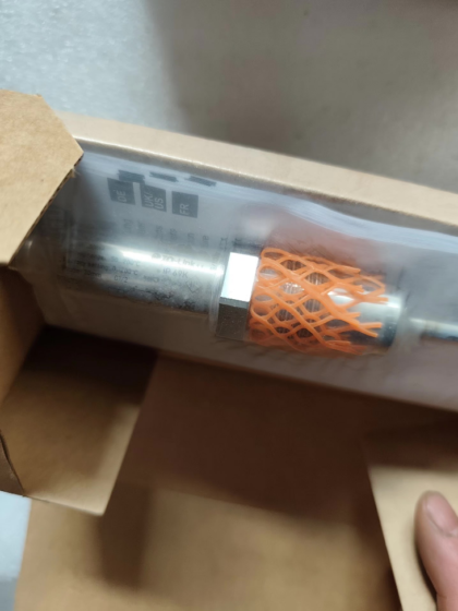
フルモデル: PM-,25BREA01-E-ZVG/US
製品タイプ: Sanitary flush diaphragm relative 圧力トランスミッター. Designed for food, beverage and pharmaceutical sanitary processes. Equipped with Aseptoflex Vario G1 external thread, cavity-free flush diaphragm, no dead space, suitable for CIP/SIP cleaning.
✅ Core Measurement Parameters
測定範囲: -0.0125 ~ 0.25 バー (-12.5 ~ 250 ミリバール / -1.25 ~ 25 kPa)
Pressure type: Gauge pressure
Overload pressure: 0.6 バー (600 ミリバール); Burst pressure: 30 バー
Factory preset: 0~250 mbar, 4…20mA analog output. Measuring range can be freely scaled via IO-Link.
Measuring element: Ceramic capacitive sensor
正確さ: Characteristic deviation < ±0.2%FS; Repeatability < ±0.1%FS; Long-term stability per year < ±0.1%FS
⚙️ Mechanical & Wetted Specifications
プロセス接続: G1 external thread (ISO228), Aseptoflex Vario sanitary seal
Wetted materials: 316L(1.4435) ステンレス鋼, 99.9% alumina ceramic diaphragm; Ra<0.4μm
ハウジング材質: 316Lステンレス; 重さ: 273.45 g; 寸法: Φ30.2 × L111 mm
Installation torque: 35 Nm
Medium temperature: -25 ~ +150 ℃, supports high-temperature sterilization
保護クラス: IP67 / IP68 / IP69K, high-pressure washdown compatible (CIP)
Electrical connector: M12 A-coded 4-pin gold-plated plug
🔌 Electrical & IOリンク
電源電圧: DC 18~30V
出力: 1 × 4~20mA analog + 1 × configurable digital switch output, IO-Link V1.1 COM2 (38.4kBaud)
サポートされている機能: Zero/span calibration, internal temperature reading, 診断情報. IO-Link resolution: 0.05 ミリバール
応答時間: 30ms for 2-wire mode; 7ms for 3-wire mode. Analog output damping adjustable from 0~4s
Features reverse polarity protection, short-circuit protection and watchdog circuit
📌 Typical Applications
Tank pressure and hydrostatic level measurement (low range) for food & beverage tanks; sanitary pressure monitoring in pharmaceutical processes; 発酵槽, fruit juice/dairy, sauce media (solids-containing, viscous media; flush diaphragm minimizes material buildup).
🔁 Alternative Selection & 同じシリーズ
PM17 series with identical housing: PM1789 (smaller measuring range); PM17xx series shares same housing with different pressure ranges.
国内代替品: Sanitary flush diaphragm transmitters with G1 thread, 316L wetted parts, 4-20mA+IO-Link for low pressure. Match overload pressure, burst pressure and surface roughness during selection.
⚠️ Installation & メンテナンスノート
- Flush diaphragm surface must be flush with tank inner wall to avoid liquid trapping dead zones.
- Strictly limit installation torque to 35 Nm; over-torque will damage ceramic diaphragm.
- Keep temperature transients during CIP cleaning within specification; never exceed burst pressure.
- IO-Link can read internal sensor temperature and diagnostic information for predictive maintenance.
IFM PM1708 Troubleshooting Checklist
Applicable for no output, pressure drift and abnormal alarms. Distinguish between 4-20mA analog signal and IO-Link digital signal. Power supply DC18~30V.
- No Output (Ammeter / PLC channel shows 0mA or fixed 4mA)
- 力 & Wiring Check (Highest Priority)
電源: Verify terminal voltage DC18~30V. Voltage drop under load shall not fall below 18V. Severe power supply ripple may also cause failure to start.
M12 4-pin A-coded pinout:
Pin1: BN Brown = +24V supply
Pin2: BK Black = 4~20mA / IO-Link signal
Pin3: BU Blue = 0V GND
Pin4: GY Grey = Switch output
Fault points:
逆極性: Reverse power connection will not burn the sensor, but results in no operation and no output. Correct wiring to restore function.
短絡: Signal wire shorted to ground → current locked, PLC reports channel fault. Disconnect sensor to test wiring separately.
2-ワイヤー / 3-wire confusion: PM1708 is a 3-wire device. Do not wire as conventional 2-wire transmitter; this easily causes abnormal signals.
測定: Disconnect load and measure supply & signal directly at sensor pins, to differentiate fault between sensor body or downstream PLC module.
- Hardware Damage / Installation Issues
Water ingress / corrosion at M12 plug: Rated IP69K, but aged seal causes reduced insulation under humid conditions. Inspect pins for oxidation or water stains.
Mechanical overload: Installation torque >35Nm leads to microcracks on ceramic diaphragm. Diaphragm damage usually accompanied by zero drift; severe cases result in total loss of output.
Frozen medium: Medium temperature below specification causes diaphragm damage.
- IO-Link Communication Failure
ボーレート: COM2 (38400). Master station parameters must match.
Check master power supply and port enablement. Excessively long cables or poor shielding cause handshake failure.
Factory reset: Send reset command via IO-Link master to restore sensor parameters.
- Pressure Drift (Zero drift, inaccurate readings; value slowly changes while pressure remains constant)
- ゼロドリフト (最も一般的な)
- Installation stress drift
Over-tightened G1 thread creates continuous stress on ceramic diaphragm, leading to slow drift even at rest. 決して超えないでください 35 Nm.
Pipeline thermal expansion / contraction pulls sensor housing and introduces mechanical stress. Loosen thread, rest for 10 分, then re-perform zero calibration for verification.
- 温度ドリフト
Large medium temperature fluctuation outside compensation range. Read internal sensor temperature via IO-Link and compare with process temperature.
Short-term drift during CIP/SIP hot-cold cycling is normal thermal effect. If readings fail to recover after cooling, diaphragm damage is suspected.
- Zero offset
Residual process material coats flush diaphragm; viscous or crystallized deposits block pressure transmission. Clean diaphragm surface.
Perform zero calibration via IO-Link under fully vented zero-pressure condition.
- Span Drift / Readings too high or too low
Verify range parameters in IO-Link: Check whether upper/lower limits have been modified accidentally. Original PM1708 range: -12.5~250 mbar.
Overload damage: Instant pressure exceeding 0.6bar overload rating permanently damages ceramic element. This type of drift cannot be fixed by zero calibration; sensor replacement required.
Hydrostatic installation offset: Hydrostatic head from mounting height for level measurement is not compensated at zero point.
- Interference-induced Drift
Power cables routed alongside sensor signal wires cause electromagnetic interference. Use shielded signal cable with single-end grounding for shield.
Poor 24V power quality with high ripple leads to jitter and drift on analog signal.
Ⅲ. Alarms / Abnormal Status (IO-Link diagnostic bit alarm, or analog output locked at fault current)
Fault current for PM1708 is configurable; typical values: 3.6ミリアンペア (low fault) or 22mA (high fault)
Read IO-Link diagnostic code first to classify fault:
- Hardware Fault (Sensor Fault): Internal measuring element failure. Zero/span calibration impossible. Replace sensor directly.
- Temperature alarm: Internal sensor temperature out of operating range (-25~150℃), caused by over-temperature during CIP or sustained high heat.
- Pressure out-of-range alarm: Process pressure exceeds configured range. Not sensor damage; verify actual process pressure.
- Parameter error alarm: Incorrect parameter download or invalid range setting. Restore factory defaults and reconfigure.
- 通信障害: IO-Link cable break or master port fault. Only digital communication fails; analog output may still operate.
- Fast On-site Troubleshooting Sequence (Follow in order)
- 電源を切る, inspect M12 plug exterior, pin corrosion and water ingress; recheck wiring definition.
- Power on under no-load condition, measure supply voltage and confirm DC18~30V.
- Read pressure value under zero-pressure condition:
Stable reading near zero → zero point OK.
Large zero offset and calibration failure → mechanical stress or diaphragm damage.
- Apply known reference pressure (calibrator) 検証用:
Calibration successful → drift caused by installation stress or material coating.
Drift persists after calibration → sensor element damaged.
- Read internal temperature and diagnostic codes via IO-Link to locate fault source.
- After eliminating external factors, swap with a spare identical sensor to confirm body fault.
- Common Misconceptions
- 誤解: Flush diaphragm can be scrubbed hard.
Alumina ceramic is wear-resistant, but sharp objects create irreversible scratches. Only gentle flushing is allowed for cleaning.
- 誤解: Repeated zero calibration fixes drift.
Frequent calibration only masks mechanical stress or cracked diaphragm; drift will reappear shortly.
- 誤解: Drift after CIP high temperature equals sensor failure.
Cool down to ambient temperature before assessment; temporary drift from thermal shock is normal.
- Spare Part Replacement Criteria (Replace if any condition met)
Zero calibration fails, IO-Link reports hardware fault
Drift cannot be eliminated after pressure overload or over-torque installation
Visible cracks or chipping on diaphragm
Water ingress and corrosion inside M12 connector with degraded insulation
IFM PM1708 Ceramic Diaphragm (Measuring Cell) Damage Assessment
PM1708 uses oil-free ceramic capacitive flush diaphragm. Diaphragm material: 99.9% alumina ceramic. Microcracks are invisible to naked eye. Assessment follows four steps: Visual Inspection → IO-Link Diagnostics → Zero / Calibration Test → Reference Pressure Comparison.
- 目視検査 (Only detects obvious breakage; microcracks cannot be seen)
Remove sensor, clean ceramic diaphragm surface and inspect under strong light:
- ✅ 通常: Uniform matte white ceramic surface, no scratches, chipping, indentation or radial cracks. Diaphragm surface flush with G1 end face.
- ⚠️ Damage signs:
Chipping, radial fine cracks or pitting on ceramic surface
Indented / bulged diaphragm (from overload impact)
Gap between ceramic and stainless steel base, or medium penetration traces
注記: Minor microcracks cannot be seen visually, and must be verified electrically or via pressure test.
Do not use hard tools to scrape ceramic surface during inspection.
- IO-Link Diagnostics (Highest Priority, built-in measuring cell monitoring)
- Read IO-Link diagnostic event: CELL Err (Measuring Cell Error). This indicates damaged ceramic capacitive element; diaphragm is damaged and cannot be repaired.
- Fault characteristics:
Persistent fixed offset; sensor detects abnormal capacitance characteristics and reports CELL Err.
Some cases trigger hardware fault alarm, analog output locks to fault current (3.6mA /22mA).
No CELL Err ≠ intact diaphragm. Minor damage may only produce zero drift without CELL Err at early stage.
Ⅲ. Zero Point Test (Most commonly used on-site method)
Prerequisite: Sensor removed, diaphragm fully exposed to atmosphere, zero pressure condition. Rest 10 minutes to release installation stress.
- Read pressure value via IO-Link and record zero reading.
普通: Stable zero reading with small deviation; zero calibration completes successfully.
Suspected damage:
Large zero offset and zero calibration failure (non-convergent calibration with error)
Recurring zero drift: Reading drifts minutes after successful calibration
Reading changes when flipping sensor orientation: Ceramic unit capacitance already compromised.
Differentiation: Installation stress drift — zero can be calibrated normally after loosening thread and resting. Diaphragm damage: zero cannot stabilize or be calibrated regardless of resting time.
- Reference Pressure Calibration (Final confirmation, lab / calibration bench)
Apply known calibrated pressure (cover range: 0, 100ミリバール, 250ミリバール) and record readings:
- ✅ Intact: Good linearity, good repeatability, small hysteresis between pressurization and depressurization; reading returns to zero after pressure release.
- ❌ Typical diaphragm damage symptoms:
Nonlinear pressure-reading curve; mismatch between pressurization and depressurization curves
Readings high/low during pressurization; zero fails to return after depressurization
Poor repeatability: Large reading variation for repeated tests at same pressure.
Once observed, ceramic diaphragm has developed microcracks, non-repairable; sensor replacement required.
- Typical Root Causes for Diaphragm Damage (for cross validation)
Installation torque>35Nm, squeezing ceramic unit (most frequent cause)
Instant pressure exceeding 0.6bar overload rating, pressure shock
Vacuum shock, repeated severe thermal shock during CIP/SIP
Hard object impact on ceramic diaphragm (during cleaning or disassembly)
- Quick Decision Rules (Direct application)
Replace ceramic diaphragm / sensor if any condition satisfied:
- IO-Link reports CELL Err / measuring cell hardware fault
- Zero calibration fails under zero-pressure condition
- Reference pressure test: zero cannot recover after pressurization / depressurization, nonlinearity, poor repeatability
- Visible cracks or chipping on diaphragm
If the following applies, diaphragm is NOT damaged (external factor)
Zero drift, but zero calibration succeeds after loosening thread and resting → mechanical installation stress, not cracked diaphragm.
Ⅶ. Common Misconceptions
- 誤解: Ceramic is hard and cannot break.
Ceramic is wear-resistant, but vulnerable to impact and compressive load. Over-torquing is the top cause of invisible internal microcracks.
- 誤解: Pressure reading available = intact diaphragm.
Microcracks may still return pressure readings at early stage, only showing drift; CELL Err alarm appears later.
- 誤解: Zero calibration can repair diaphragm.
Offset caused by microcracks is permanent damage. Calibration only temporarily masks drift, which will recur.
IFM PM17xx Same Series List (Identical housing as PM1708: Aseptoflex Vario G1 external thread, ceramic flush diaphragm, 4-20mA+IO-Link, IP69K, M12 4-pin)
Common features: Identical outline dimension, installation torque 35Nm, wetted material, electrical interface and diagnostic logic. Only measuring range differs. Mechanically interchangeable (only IO-Link range parameters need reconfiguration).
| モデル | 範囲 (Gauge Pressure) | Overload Pressure | 応用 |
| PM1789 | -0.002 ~ 0.04 バー (-2~40 mbar) | 0.4 バー | Ultra-low micro-pressure, tank micro-vacuum, ultra-low hydrostatic level for fermenters |
| PM1708 | -0.0125 ~ 0.25 バー (-12.5~250 mbar) | 0.6 バー | Food tank pressure, low hydrostatic level (your current model) |
| PM1718 | -0.05 ~ 0.4 バー (-50~400 mbar) | 0.8 バー | Slightly higher tank pressure, 空の + low pressure process |
| PM1717 | -0.1 ~ 1.6 バー (-100~1600 mbar) | 3.2 バー | General tank pressure, level measurement with negative pressure |
| PM1707 | -0.05 ~ 1 バー (-50~1000 mbar) | 3 バー | Medium-low pressure sanitary process |
| PM1709 | -1 ~ 1 バー | 3 バー | 真空 + low pressure, vacuum tank, degassing process |
| PM1703 | -1 ~ 25 バー | 37.5 バー | High-pressure sanitary piping, sterilization loop |
Similar Housing Alternative Series (Compatible with Aseptoflex adapter)
PI17xx (Aseptoflex G1 flush diaphragm, similar appearance with LED status indicator)
PI1708: Same range as PM1708 (-12.5~250 mbar), with LED indicator, other parameters similar. Preferred field replacement option for PM1708.
PI1717 / PI1707 / PI1703: Corresponding PM17 range versions with LED display.
PY Series (Sanitary flush diaphragm, oil-filled metal diaphragm, not ceramic, better high-temperature resistance for CIP)
PY20xx: Metal diaphragm, suitable for higher temperature and high pressure shock media. Diaphragm principle differs; fault diagnosis logic is not equivalent to PM17 ceramic diaphragm.
Replacement Selection Notes
- All PM17 models use ceramic diaphragm same as PM1708; identical troubleshooting method. Mechanical interface fully compatible. Reconfigure range via IO-Link after swap.
- PI17xx: Added LED indicator; mechanical, 電気, installation torque and Aseptoflex seal remain unchanged. Widely used for project replacement of PM1708.
- PY series uses oil-filled metal diaphragm, not ceramic. Diaphragm damage judgment method differs, not recommended as direct equivalent for PM17.
Not Recommended for Mixing
PM16 series: G1/2 thread, different process connection, cannot use PM17 Aseptoflex Vario adapter.
PI27/PI28: Local digital display, longer housing, different installation dimension.
Quick Selection Advice
Replace PM1708: Prefer PI1708 (same range, 導かれた, compatible interface)
Same housing upgrade for higher micro-pressure: PM1718
Smaller micro-pressure range: PM1789





NH42-63-318x560.png "CHINT PC型自動切替スイッチ (ATS)NH42-63/4SZ")



