 コンタクタ,サーキットブレーカー,ソーラーインバーター,電気メーター,太陽電池


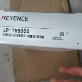
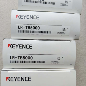
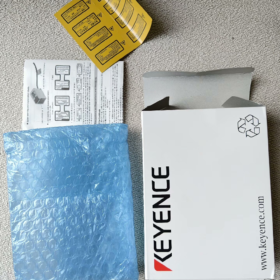
キーエンス LR-TB5000 はアンプ内蔵 TOF レーザー距離 センサー キーエンスLR-Tシリーズの. 長距離検出用の拡散反射モデルです。, 標準ストレートケーブルを装備し、レーザークラスに分類されます 2. Time-of-Flight測定原理を採用, 60mm~5000mm以内で安定した距離測定と物体存在検出を実現します。. 性能は色の影響をほとんど受けません, ターゲットの材質または表面角度. IP65/IP67の高度な侵入保護を備えています, 産業オートメーションの生産ラインなどの複雑な作業条件に広く適用されています。, ロジスティクス & 倉庫および建設機械. 産業現場での長距離かつ信頼性の高い検出に主流の選択肢です.
- モデルコードの内訳
モデル: LR-TB5000
| コードセグメント | 説明 |
| LR-T | 製品シリーズ: アンプ内蔵TOFレーザセンサの一般シリーズ |
| B | 検出タイプ: 拡散反射型 (反射板は必要ありません, ターゲット表面を直接検出) |
| 5000 | 標準最大検出距離: 5000mm (5メートル), 基準として白いマット紙でテストしました |
| サフィックスなし | ケーブル差込口: ストレートケーブルタイプ; レーザークラス: クラス 2 (IEC60825-1およびFDAに準拠(CDRH) 標準) |
同系列接尾辞の補足規則: 接尾辞「C」は M12 コネクタ タイプを表します; 接尾辞「CL」は、低出力レーザークラスの M12 コネクタを表します。 1.
- 主要な技術仕様
2.1 検出性能
| パラメータ | 仕様 | 備考 |
| 標準検出範囲 | 60 ~ 5000 mm | 表示範囲: 50~5200mm; 白いマット紙でテスト済み |
| 光源 | 赤色半導体レーザー, 波長: 660nm | レーザークラス 2, マックス. 出力電力≤1mW |
| スポット径 | 変数, ≦φ40mm | スポットサイズは検出距離に応じて直線的に変化します |
| 応答時間 | 5 選択可能なレベル: 1MS / 10MS / 25MS / 100MS / 1000MS | 必要に応じて応答速度と検出精度のバランスをとります |
| 相互干渉の除去 | まで 4 同じモデルのユニットをグループ内に近接して設置することができます | 機能は干渉防止が有効になった後に有効になります |
| 検出ロジック | 複数のモード: 閾値判定, ウィンドウの比較, ピークホールド, バレーホールド, 等. | オンボードボタンで設定を確認可能 |
| タイマー機能 | オフ / オンディレイ / オフディレー / ワンショットパルス (オプション) | 遅延時間はパラメータでカスタマイズ可能 |
2.2 電気的特性
| パラメータ | 仕様 |
| 供給電圧 | 12~24VDC (ピークツーピークリップル ≤10%) |
| 消費電流 | ≤45mA (24VDC電源, 無負荷) |
| スイッチ出力 | NPN/PNPオープンコレクタ切替可能; 定格DC30V以下, 50ミリアンペア; NO/NC選択可能 |
| アナログ出力 | 選択可能な4〜20mA電流 / 0~10Vの電圧; 外部入力とピンを共用 |
| 外部入力 | リモートチューニングとモード切り替えをサポート; アナログ出力とピンを共有 |
| 通信プロトコル | IO-Link v1.1はリモートパラメータ設定とデータ取得に対応 |
2.3 環境 & 物理パラメータ
| パラメータ | 仕様 |
| 侵入保護 | IP65 / IP67 (IEC60529に準拠) |
| 動作温度 | -20 ~+55℃ (凍結や結露がないこと) |
| 動作湿度 | 35 ~ 85% RH |
| 周囲光耐性 | 白熱灯 / 日光: ≤100000ルクス |
| 耐振動性 | 10~55Hz, 複振幅1.5mm, 2 X/Y/Z 軸ごとに時間 |
| 耐衝撃性 | 1000 m/s², 6 X/Y/Z 軸ごとの時間 |
| 主な材質 | ハウジング: ニッケルクロムメッキ亜鉛鋳物; レンズカバー: 耐傷性コーティングPMMA; ケーブル: PVC |
| 重さ | 約. 125g (標準ケーブル付き) |
| 認証 | UL, CSA |
- シリーズ内のモデル間の比較
| モデル | 検知範囲 | ケーブルコンセント | レーザークラス |
| LR-TB5000 | 60~5000mm | ストレートケーブル | クラス 2 |
| LR-TB5000C | 60~5000mm | M12コネクタ | クラス 2 |
| LR-TB5000CL | 60~5000mm | M12コネクタ | クラス 1 |
| LR-TB2000 | 60~2000mm | ストレートケーブル | クラス 2 |
- ケーブルバージョンのピン定義
LR-TB5000は多芯ストレートケーブルを採用. 標準的なワイヤ定義は次のとおりです。:
| ワイヤーの色 | 関数 | 説明 |
| 茶色 | パワーポジティブ (+V) | 12~24VDC 電源入力 |
| 青 | パワーマイナス (0V/GND) | 電源と信号の共通グランド |
| 黒 | スイッチ制御出力 | NPN/PNP選択可能, 通常はデフォルトで開きます |
| 白 | アナログ出力 / 外部入力 | 設定可能: 4-20mA/0-10Vアナログ出力または外部トリガ入力 |
注記: 8芯延長ケーブルはピン定義が異なります. アナログ出力と外部入力は同時に使用できません; メニュー設定による機能の切り替え.
- 代表的な用途
- ロジスティクス & 倉庫保管: 自動倉庫の在室検知, AGV の障害物測距, 選別ラインでの製品有無確認. 長距離対応で大規模な倉庫スペースに最適.
- 自動車製造: ボディコンベアライン上のワークステーションの位置決め, ツーリング治具の検出, 大型プレス部品の位置判定. 耐油性と耐周囲光性により、過酷な作業場の条件に適応します.
- 建設機械: 昇降プラットフォームの高さ制限, メカニカルアームの位置検出, 材料杭の高さ測定. 広い温度耐性と高い保護レベルが屋外の過酷な環境に適合します.
- 3C & 包装産業: 生産ラインの部品カウント, ロール材残存検知, 梱包された商品の高さ検査. 狭い設置スペースにもフィットするコンパクトボディ.
- インテリジェント機器: 円形コンベア上でのワークの位置決め, 昇降装置のストローク制御, マルチステーションでの物体検出. 複数のセンサーの干渉のないネットワークをサポート.
- トラブルシューティング マトリックス
| 故障現象 | 根本的な原因 | ソリューション |
| 表示灯も出力もありません | 1. 配線の間違いまたは電源電圧の異常 | 1. 茶色と青色のワイヤ間の電圧を測定し、12〜24VDCであることを確認します |
| 2. 過負荷プルダウン電圧 | 2. 逆接続を避けるために極性を確認してください | |
| 3. ハードウェア障害 | 3. 短絡を排除するための独立したテストのために外部負荷を切断します | |
| 4. 応答がない場合は交換または返品修理 | ||
| 不安定な検出 & 頻繁な誤作動 | 1. 極端な反射率 (ピュアブラック / 鏡面) | 1. 鏡面反射を避けるために取り付け角度を調整してください |
| 2. 安定検出範囲外のターゲット | 2. ターゲットが60~5000mmの範囲内にあることを確認してください | |
| 3. 強い光がレンズに直接照射される | 3. 直射日光や強い光を遮るフードを設置してください | |
| 4. 複数のセンサー間の信号干渉 | 4. 干渉防止とセンサー位置のずらしを有効にする | |
| 検出偏差が大きい & 精度が低い | 1. ベンチマーク調整が完了していません | 1. 基準面によるオートチューニングを行う |
| 2. 応答時間が短すぎる | 2. 応答時間を適切に延長して安定性を向上させる | |
| 3. 対象面の傾き角が大きすぎる | 3. レーザーがターゲットに対して垂直になるように設置を調整します | |
| アナログ出力の異常 | 1. ピン機能の構成が正しくありません | 1. I/Oメニューに入り、アナログ出力モードを確認します。 |
| 2. 負荷インピーダンスの不整合 | 2. インピーダンス要件に従ってください: 電流出力の場合は ≤500Ω, 電圧出力の場合は ≥10kΩ | |
| 3. 未校正のアナログ範囲 | 3. アナログ出力の完全な 2 点校正 | |
| エラーコードが表示される | 1. 一時的な内部システム障害 | 1. 電源を入れ直し、一時的な異常を解消します |
| 2. パラメータ設定が間違っている | 2. 工場出荷時のデフォルトパラメータを復元する | |
| 3. レーザーモジュールのハードウェア障害 | 3. エラーが解決しない場合はアフターサービスにお問い合わせください |
- 禁止されている操作 & 安全規則
- レーザーの安全性: レーザーエミッターを直接見たり、レーザー光線を人の目に向けたりしないでください。. 長期にわたるクラスへの曝露 2 レーザーは目に損傷を与える可能性があります.
- 環境要件: 爆発性ガス雰囲気では使用しないでください. 本体を長時間液体に浸さないでください。. IP67 は一時的な水飛沫および防塵のみを目的としています。.
- 電気的要件: DC12~24Vを超える電圧を加えないでください。. スイッチ出力をAC電源に直接接続しないでください。. 電磁波障害を防ぐため、電源ケーブルとの同時配線は避けてください。.
- インストール要件: 仕様を超える振動や衝撃のある場所には取り付けないでください. レンズや放熱構造をふさがないでください。. レンズにシールやカバーなどを貼らないでください.
KEYENCE LR-TB5000 拡散反射型センサの検出原理
LR-TB5000 は、拡散反射型パルス飛行時間型 (TOF) レーザーセンサー. その検出原理は 2 つのコア部分で構成されています: 拡散反射光路構造 (光の伝播と検出モードを決定します) およびパルスTOF測距アルゴリズム (距離計算のコアロジック). 複合設計により反射板なしで長距離安定検出が可能, ターゲット特性の影響を最小限に抑えます.
7.1 拡散反射光路の仕組み
この統合センサーは、送信機と受信機を組み合わせた設計を採用しています。. 作業工程は以下の通りです:
- 内部レーザー送信機は、コリメートされた赤色レーザー パルスをレンズを通して前方に放射します。.
- レーザーがターゲット表面に当たるとき, 光はあらゆる方向に散乱します (拡散反射) ほとんどの工業用ワークピースの表面が粗いため.
- 散乱光の一部は元の経路に沿って戻ります, 受光レンズに入り、内部の光電受光器で捕捉されます。.
従来の拡散光電センサーとの本質的な違い:
従来の拡散センサーは受光強度で物体の有無を判断. 暗い吸収性の物体では検出が失敗しやすい, 反射光が不十分または過剰であるため、高光沢ミラーまたは長距離ターゲット.
LR-TB5000は反射光の時間信号のみに基づいて距離を計算します。. 戻り光がタイミングをトリガーする最小しきい値に達している限り、正常に動作します。, ターゲットの色の影響をほとんど受けません, 材質と表面角度.
7.2 パルス TOF レンジングの中心原理
TOF (飛行時間) コアテクノロジーです. センサーとターゲット間のレーザー光の往復移動時間を測定することで絶対距離を計算します.
式:
$$ d = \frac{c \times \Delta t}{2} $$
$d$: センサーとターゲット間の実際の距離
$C$: 空気中での光の速度 (約. $3\times10^8\ \text{MS}$)
$\デルタt$: レーザーパルスの発射から受信までの往復時間
で割る 2: レーザーは円形の経路を移動します (発光→反射→受信)
作業手順:
- 駆動回路はレーザーダイオードを制御してナノ秒の狭いパルスを放射します。, その間、高速タイミング回路がカウントを開始します。.
- 反射したレーザーは高感度フォトダイオードによって電気信号に変換されます, タイミング回路を停止します.
- 内蔵MCUは温度補償と環境光補正を備えた時差データを処理します, 次にデータをリアルタイムの距離値に変換します.
- 計算された距離は、事前に設定されたしきい値と検出ウィンドウと比較されます。. センサーは対応するスイッチ/アナログ信号を出力します。, 生の距離データはIO-Link経由で送信可能.
7.3 主要な技術的な最適化
クラス準拠で安定した5m拡散検知を実現 2 レーザーの安全基準, センサーは複数の最適化された設計を採用しています:
- 狭いパルス & 高ピークパワーレーザー
ナノ秒超狭パルス駆動技術により、高い瞬間電力と低い平均電力を実現. クラスを満たす 2 目の安全要件を満たし、長距離の微弱な反射光からの識別可能な信号を保証します。.
- 高SNR受信回路
バンドパス光フィルターと専用信号処理チップを搭載, 一致したレーザーパルスにのみ反応します. 白熱光や日光からの干渉を効果的に抑制します, 周囲光の下でも安定して動作します。 100,000 ルクス.
- 温度ドリフト補償アルゴリズム
内蔵の温度センサーにより、光速度とタイミング回路の温度変化による偏差を補正します。, -20~55℃の範囲で安定した検出精度を維持.
- 相互干渉抑制
複数のセンサーを近接して設置する場合, 干渉防止機能を有効にする. レーザーパルスは自動的にずらされ、信号間の誤判断を防ぎます. まで 4 センサーはグループで動作可能.
7.4 拡散反射検出の適用限界
動作原理に基づく制限:
安定した検出: 最もマットな, 粗いおよび半光沢のワークピース, 色に関係なく (黒/白/色付き) そして素材 (金属/プラスチック/木材).
限定的な検出: 急傾斜の全面鏡面 (すべての光が受信機から反射される), 厚い黒の植毛素材 (閾値以下の戻り光), 透明/半透明のオブジェクト (レーザーは透過または屈折します).
最小限のブラインドゾーン: 60mm. 60mm以内のターゲットは正常に検出できません.

 インパルスヒートシール温度調節器")


 リレー")
")


NH42-63-318x560.png "CHINT PC型自動切替スイッチ (ATS)NH42-63/4SZ")


