 コンタクタ,サーキットブレーカー,センサー,エンコーダ,PLC,コンバータ

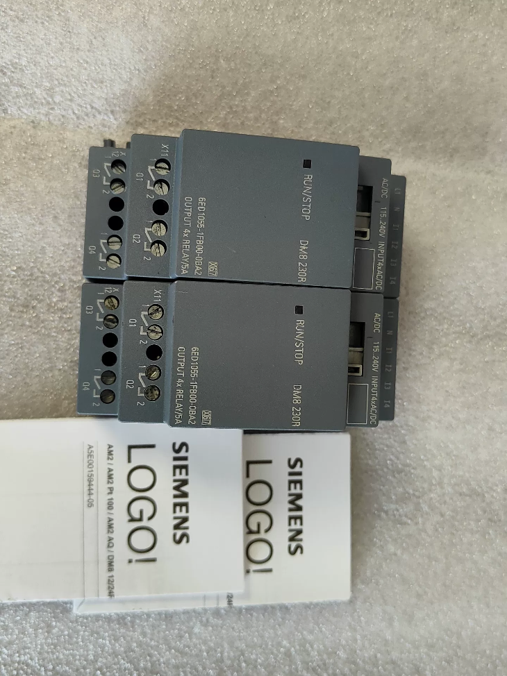

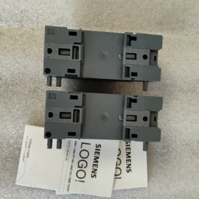
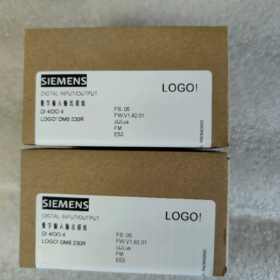
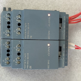
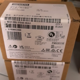
フルネーム: ロゴ! DM8 230R Digital I/O 拡張モジュール (ロゴ! 8 シリーズ)
- モデルコードの解釈
6ED1055-1FB00-0BA2
6ED1055: Prefix for LOGO! 8 series expansion modules
1FB: DM8 230R, 115/230 V AC/DC電源, 4DI/4DO relay output
00: ハードウェアバージョン
0BA2: Firmware version (ロゴ!8 プラットフォーム, incompatible with LOGO!6/7 (0BA6/0BA7) main units)
- コアの電気仕様
| アイテム | 仕様 |
| 電源 | 115~230 V AC/DC (85~265 V AC; 100~253 V DC) |
| DI デジタル入力 | 4 チャンネル, universal AC/DC signal |
| 論理 0: <40 V AC /<30 V DC | |
| 論理 1: >79 V AC />79 V DC | |
| Input delay: 0→1=40 ms; 1→0=75 ms | |
| デジタル出力DO | 4 channels relay normally-open isolated contacts |
| 抵抗負荷: 5 あ / 250 Vと | |
| Inductive load: 3 あ / 250 Vと | |
| Minimum load current: 100 ミリアンペア | |
| 最大スイッチング周波数: 2 Hz (抵抗性の); 0.5 Hz (誘導的な) | |
| 取り付け | 35 mm DINレール, 幅 2 TE (35.5 mm) |
| 全体の寸法 | W35.5 × H90 × D58 mm |
| 保護クラス | IP20 (キャビネット設置のみ) |
| 動作周囲温度 | -20 ℃~ +55 ℃, 結露なし |
| 重さ | 約. 0.17 kg |
- Compatibility Instructions
✅ Supported Main Units: ロゴ! 8 / 8.2 / 8.3 (0BA8 and later firmware)
Typical main unit models: 6ED1052-1FB08-0BA0, 6ED1052-1FB08-0BA1 and other 230 V main units
❌ Not Supported: ロゴ! 6, ロゴ!7 (0BA6/0BA7) main units. Backplane bus protocol differs, communication not available
- 端子の定義 (トップ: 力 & 入力; 底: 出力)
Upper Terminals (電源 + 入力)
L1, N: Module operating power supply
I1, I2, I3, I4: 4 デジタル入力
Lower Terminals (リレー出力)
Q1, 第2四半期, Q3, Q4: 4 independent relay normally-open contact groups (2 terminals per channel, no common terminal)
⚠️重要: Four relays are electrically isolated; different voltage circuits can be connected to each channel independently
- 典型的なアプリケーションシナリオ
Small HVAC control, ウォーターポンプ & ファンコントロール, 照明回路, door interlock, simple conveyor lines. Ideal for sites equipped with existing 220 V AC sensors and contactor circuits without additional DC power supply.
- 選定ガイドライン & よくある落とし穴
- Input signal must exceed 79 V to be reliably recognized as logic 1; low voltage signals cannot be used.
- Relay mechanical contacts not suitable for high-frequency switching. Select transistor output modules for frequent operation.
- Maximum expansion limit: A single LOGO! main unit can connect up to 4 expansion modules.
- All input channels are recommended to use the same phase power. Do not connect I1~I4 across different phases to avoid false triggering caused by induced voltage.
- Install RC snubbers or freewheeling diodes in parallel with inductive loads (接触器, 電磁弁) to extend relay service life.
- Comparison with Similar Series Models
6ED1055-1FB10-0BA2 (DM16 230R): 8DI+8DO relay version with doubled I/O capacity
6ED1055-1HB00-0BA2 (DM8 24R): 24 V DC powered version
Complete Technical Documentation for シーメンス 6ED1055-1FB00-0BA2 (ロゴ! DM8 230R)
- 製品基本情報
注文番号: 6ED1055-1FB00-0BA2
製品名: ロゴ! DM8 230R Digital Expansion Module (ロゴ!8 シリーズ)
関数: 4から / 4DO relay output expansion module
位置決め: Extend I/O capacity for LOGO!8/8.2/8.3 main units, cannot run standalone
- Full Model Code Interpretation
6ED1055 1FB00 0BA2
- 6ED1055: ロゴ! 8 series expansion module category
- 1FB: DM8 230R, 115~230 V AC/DC power supply, 4-channel AC input, 4 independent normally-open relay outputs
- 00: Hardware revision
- 0BA2: Firmware version (ロゴ!8 プラットフォーム, incompatible with LOGO!6/7 (0BA6/0BA7) コントローラー)
- Detailed Electrical Specifications
3.1 電源
| パラメータ | 仕様 |
| 定格電圧 | 115…230 V AC/DC |
| 動作範囲 | 交流: 85~265 V; 直流: 100~253 V |
| 周波数範囲 | 47~63 Hz |
| Module Power Consumption | マックス. 2.2 バージニア州 |
3.2 DI デジタル入力 (I1, I2, I3, I4)
量: 4-channel universal AC/DC input
論理 0: <40 V AC / <30 V DC
論理 1: >79 V AC / >79 V DC
Input response delay: 0→1: 40 MS; 1→0: 75 MS
入力タイプ: Passive AC voltage input, 24 V DC signals are not allowed
Maximum cable length: 100 メートル (unshielded cable)
3.3 Relay Output DO (Q1~Q4, isolated normally-open contacts)
⚠️ Four relays are mutually isolated; different voltage circuits can be wired to each channel
|負荷の種類|接点の定格|
| —| —|
|抵抗負荷 (Resistors, 点灯)|5 あ / 250 Vと|
|誘導負荷 (コンタクタ, 電磁弁)|3 あ / 250 Vと|
|Minimum Carry Current|100 ミリアンペア (Poor contact performance may occur below this value)|
|Max Switching Frequency|抵抗負荷: 2 Hz; Inductive load: 0.5 Hz; Mechanical no-load limit:10 Hz|
|禁止されている操作|Parallel connection of multiple output contacts for current boosting is forbidden|
- 機械式 & 環境パラメータ
取り付け: 35 mm標準DINレール
幅: 2 TE (35.5 mm)
全体の寸法: W35.5 × H90 × D58 mm
重さ: 約. 170 g
保護クラス: IP20 (indoor cabinet use only)
動作温度: -20 ℃~ +55 ℃ (condensation prohibited)
ストレージ & 輸送温度: -40 ℃~ +70 ℃
相対湿度: 5% ~ 95%, 結露なし
耐振動性: IECに準拠 60068-2-6
- 端子の定義
Upper Terminals (電源 + 入力)
L1, N: Module operating power supply 115~230 V AC/DC
I1, I2, I3, I4: 4 デジタル入力
Lower Terminals (リレー出力)
Q1 two terminals: 1st relay normally-open contact
Q2 two terminals: 2nd relay normally-open contact
Q3 two terminals: 3rd relay normally-open contact
Q4 two terminals: 4th relay normally-open contact
- System Compatibility Rules
✅ Supported Main Units (ロゴ!8 Platform)
6ED1052-1FB08-0BA0, 6ED1052-1FB08-0BA1, all LOGO!8.2 / 8.3 230 V controllers
Maximum expansion quantity: まで 4 expansion modules per LOGO! 本体
❌ Incompatible Equipment
ロゴ!6 (0BA6), ロゴ!7 (0BA7) legacy controllers. Backplane communication protocol mismatch, cannot be recognized.
- Software Configuration Requirements
プログラミングソフトウェア: ロゴ! Soft Comfort V8.0 or higher
- Select corresponding expansion module model in project hardware catalog;
- I/O addresses of expansion modules automatically follow main unit addresses, no manual assignment required;
- Verify hardware list before program download to avoid errors caused by version mismatch.
- 認証
CE, UL, CSA, CQC; ENに準拠 61010-1, で 55011 (EMC Class B, applicable for commercial building environments)
- エンジニアリング実装ガイドライン (Official Specifications)
- RC snubbers must be connected in parallel with inductive loads (電磁弁, 接触器コイル) for AC circuits to extend relay lifespan.
- All input channels are recommended to adopt power supply from the same phase. Do not connect input terminals across different phases to prevent false triggering induced by stray voltage.
- Mechanical relay contacts have limited service life. Select transistor output modules (DM8 24T) for high-frequency start-stop applications.
- The module must be installed horizontally; vertical inverted installation is prohibited.
- Maintain heat dissipation clearance in control cabinets to avoid heat accumulation when multiple modules are mounted side by side.
- Comparison Table of Similar Models
| 注文番号. | モデル | 電源 | I/O構成 | 出力タイプ |
| 6ED1055-1FB00-0BA2 | DM8 230R | 115~230 V AC/DC | 4D/4C | リレー |
| 6ED1055-1FB10-0BA2 | DM16 230R | 115~230 V AC/DC | 8D/8C | リレー |
| 6ED1055-1HB00-0BA2 | DM8 24R | 24 ワシントンDCで | 4D/4C | リレー |
Engineering Application Cases for Siemens 6ED1055-1FB00-0BA2 (ロゴ! DM8 230R)
主な利点: Direct acquisition of 115~230 V AC/DC signals; isolated relay contacts directly drive 220 V loads without additional DC power supply. Matched with LOGO! 230RCE main unit (6ED1052-1FB08-0BAx). Suitable for new construction and retrofit projects with fully AC control circuits on site.
I/Oの割り当て: 4から (220 V AC input) + 4 independent normally-open relay outputs
場合 1: Dual Sewage Pump Automatic Alternation Control for Basement Sump (Building Water Supply & 排水)
- Project Requirements
Two 220 V sewage pumps for underground parking sump; high/low level float switches with 220 V contact signals.
High water level: Start pumps; ultra-high level: Dual pumps run simultaneously + audible & 視覚的なアラーム;
Low water level: All pumps stop;
Automatic timing alternation between main/standby pumps for uniform wear; Manual/Auto switching and fault feedback function.
- ハードウェア構成
本体: 6ED1052-1FB08-0BA1 (ロゴ! 230RCE, onboard 8DI/4DO)
拡張モジュール: 6ED1055-1FB00-0BA2 ×1 (DM8 230R)
- I/O Assignment
Onboard Channels of Main Unit
I1: Auto/Manual Switch; I2: Manual Start Pump 1; I3: Manual Start Pump 2; I4: 非常停止;
Q1: Contactor of Pump 1; 第2四半期: Contactor of Pump 2;
Expansion Channels of DM8 230R
I5 (Module I1): Low Level Float Switch; I6 (Module I2): High Level Float Switch; I7 (Module I3): Ultra-High Level Float Switch; I8 (Module I4): スペア;
Q5 (Module Q1): Ultra-high level alarm buzzer; Q6 (Module Q2): Fault indicator light; Q7, Q8: スペア
- Solution Highlights
Float switches connect directly to module 220 V inputs without intermediate relays. Four isolated relay contacts can drive alarms and indicator lights separately with independent power circuits. No extra DC24V power supply required inside control cabinet, 配線の簡素化.
場合 2: 新鮮な空気 & Exhaust Fan Interlock Control for Office Building (空調設備)
- Project Requirements
Four 220 V fresh air/exhaust fans with scheduled operation, temperature linkage, fan running feedback and fault alarm. Main unit onboard I/O insufficient, expanded by additional module.
- Hardware List
ロゴ! 230RCE Main Unit + 6ED1055-1FB00-0BA2 ×1
- Module Utilization
DI Channels: 4-channel contactor running feedback signals (220 V);
DOチャンネル: Control contactors for extra two exhaust fans, fault audible & 視覚的なアラーム, system running indicator light.
- Engineering Features
All control signals are 220 Vと; isolated relay contacts allow different phase power feeding. Compact 2TE width saves DIN rail space for wall-mounted small control cabinets.
場合 3: Timed Group Control of Plant Lighting (Building Lighting System)
- 要件
Multiple groups of 220 V lighting circuits for plant road and perimeter lighting; Time-based staged switching via internal real-time clock; Local manual pushbutton override; Fault status feedback.
- ハードウェア構成
ロゴ! 230RCE (Built-in Real-Time Clock) + DM8 230R (6ED1055-1FB00-0BA2)
- Module I/O Assignment
から: 4-channel local manual pushbuttons (220 V signal);
する: Drive AC contactor coils for 4 lighting groups.
- 選定理由
Module relay supports maximum 5 A resistive load, capable of directly driving small contactors. Lighting circuits are electrically isolated; single circuit failure will not affect others.
場合 4: Simple Automatic Transfer Switch for Dual Power Supply of Small Pump Station
- プロセス要件
Two 220 V control power sources (主要 + 待機する). Automatically switch to standby power upon main power failure; interlock to prevent parallel operation; status indication and fault alarm available.
- ハードウェア構成
ロゴ! 230RC Main Unit + 6ED1055-1FB00-0BA2
- I/O Assignment
Expansion DI: Dual power supply voltage detection feedback signals;
Expansion DO: Control closing coils of two circuit breakers and switching completion indicator.
This configuration is widely adopted in power distribution renovation projects and listed as official typical application by Siemens.
場合 5: Greenhouse Evaporative Cooling Fan & Spray Solenoid Valve Interlock Control (Agricultural Automation)
要件
Automatically activate cooling fans and spray solenoid valves when temperature & humidity exceed threshold; delay shutdown; local manual buttons and equipment fault feedback.
ハードウェア
ロゴ! 230RCE + DM8 230R
Expansion DI: Manual pushbuttons, thermal relay fault feedback of fans;
Expansion DO: 220 V spray solenoid valve, standby fan contactor.
知らせ
Solenoid valves belong to inductive loads. Install AC RC snubbers in parallel with relay outputs to extend relay operating life.
場合 6: Safety Gate, Conveyor and Warning Light Interlock for Light-Duty Conveying Equipment (OEM Machinery)
制御ロジック
Conveyor allowed to start only when safety guard gate is closed; conveyor stops immediately once gate opens; warning light stays on and buzzer sounds intermittently during operation; emergency stop has highest priority.
ハードウェア構成
ロゴ! main unit I/O capacity insufficient, expanded via 6ED1055-1FB00-0BA2:
から: Safety door limit switch, 非常停止, リセットボタン;
する: Conveyor contactor, audible & 視覚的なアラーム.
General Engineering Mandatory Specifications for All Cases
- ✅ Input Wiring Rule: 全て 4 DI channels must be powered by the same phase L + N. Do not wire I1~I4 across different live phases to avoid false triggering caused by induced voltage.
- ✅ Relay outputs are isolated normally-open contacts; different voltage circuits can be wired to each channel.
- ✅ Snubber components are mandatory for inductive loads (接触器, 電磁弁).
- ✅ Maximum 4 expansion modules can be cascaded with one LOGO! 本体.
- ✅ Only compatible with LOGO!8 / 8.2 / 8.3 main units (0BA8 firmware). ロゴ!7 and earlier versions are not supported.
- ✅ Cannot operate independently; must be stacked on the right side of LOGO! main unit via expansion bus.





NH42-63-318x560.png "CHINT PC型自動切替スイッチ (ATS)NH42-63/4SZ")



