 접촉기,회로 차단기,감지기,인코더,PLC,변환기

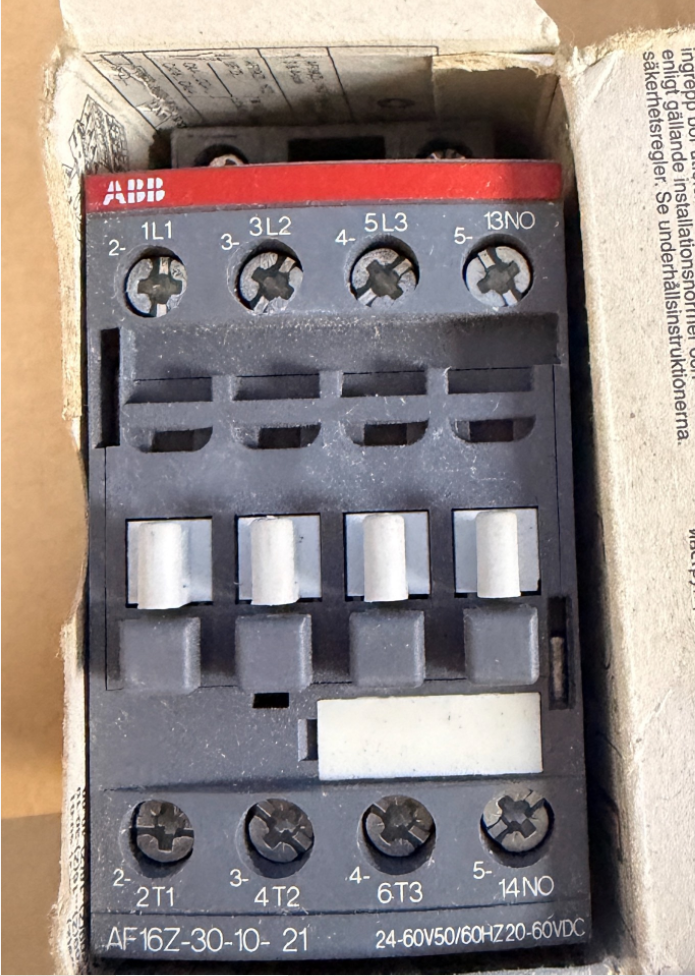

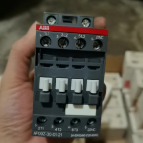
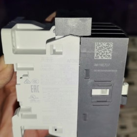
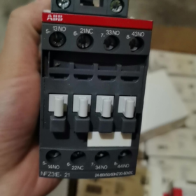
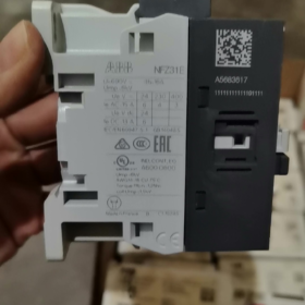
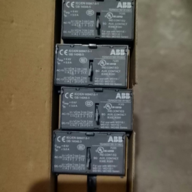
Original Factory Order No.: 1SBL176001R2110
- 모델 분석 정의
AF16Z 30 10 21
- AF16Z: AF 시리즈; Z = Low-power electronic wide-range coil (direct PLC drive capable); 프레임 크기 16 수업
- 30: 주요 연락처: 3 평상시 열림 (3아니요), no main Normally Closed contacts
- 10: 내장형 보조 접점: 1 평상시 열림 (1아니요), 0 평상시 닫힘
- 21: Coil code → Control voltage: 24~60 V AC 50/60Hz / 20~60 V DC
⚠️ Difference between AF…Z and standard AF: Extremely low coil power consumption, supports direct driving by DC24V PLC outputs, resistant to voltage dips (compliant with SEMI F47).
- Core Electrical Ratings
Maximum main circuit voltage: 690 뷔와
AC-1 (저항 부하), ≤40°C ambient: 30 에이
AC-3 (3-위상 모터, 400 다섯): 18 에이, 적합하다 7.5 kW 모터
AC-3 (690 다섯): 10.5 에이, 최대. 9 kW
설치: DIN 레일 장착, 나사식 터미널 연결
전체 치수: 여 45 mm×H 86 mm×D 77 mm
작동 온도: -40~+70 °C (without thermal overload relay); -25~+60 °C (with thermal overload relay)
- Key Coil Characteristics
Wide-range AC/DC universal: AC 24~60 V / DC 20~60 V
내장형 서지 억제; no external RC snubber or diode required
Low holding power consumption, ideal for continuous energized operation
단기적인 전압 변동 및 전압 강하를 견딥니다.
- 터미널 식별
주회로: 1L1-2T1, 3L2-4T2, 5L3-6T3
보조 접점: 14아니요 (평상시 열림)
- 일반적인 대안 & 구별
- AF16Z-30-10-11: 동일한 전압 범위, 표준 AF 코일 장착 (비 저전력 Z 코일); 저전류 PLC 출력으로 직접 구동할 수 없습니다., 교환불가.
- AX16-30-10: AX 이코노미 시리즈, 전자 광역 코일 없음, 고정 제어 전압; AF16Z를 대체할 수 없습니다.
- 1NO의 경우 + 1NC 보조 접점: 모델 AF16Z-30-11-21 선택.
- 일반적인 응용 분야
가변 주파수 드라이브의 업스트림, 팬 & 물 펌프, HVAC 장비, 반도체 기계, PLC DC 출력 직접 부하 제어, 전압 변동에 대한 높은 내성이 요구되는 산업 현장.
씨줄 AF16Z-30-10-21 접촉기 설치 기술 문서
주문번호: 1SBL176001R2110
- 일반 안전 지침
⚠️ 모든 설치, 배선 및 유지보수 작업은 모든 전원을 차단한 상태에서 수행해야 합니다.; 잠금-태그아웃 절차는 필수입니다.. 작업은 자격을 갖춘 전기 기술자만 수행해야 합니다..
- 보호 등급: IP20. 캐비닛 설치 전용. 야외에 설치하지 마십시오., 습한 환경, locations with heavy dust or corrosive gas exposure.
- 적용 가능한 표준: IEC/EN 60947-1, IEC/EN 60947-4-1; UL/CSA certified.
- AF16Z is equipped with a low-power electronic wide-range coil with integrated surge suppression circuit. No external RC snubber or diode connection is required.
- 기본 제품 정보
2.1 모델 정의
AF16Z: AF 시리즈, 프레임 크기 16, Z = low-power electronic coil
30: 3 상시 개방형 주 접점
10: 내장 1 상시 개방형 보조 접점
21: Coil voltage range AC 24~60 V 50/60Hz / DC 20~60 V
2.2 전체 치수
너비 45 mm × Height 86 mm × Depth 77 mm
2.3 Rating Summary Table
| 목 | 매개변수 |
| AC-1 저항 부하 (40 째C) | 30 에이 |
| AC-3 모터 부하 (400 다섯) | 18 에이, 호환 가능 7.5 kW 3-phase motor |
| 최대 작동 전압 | 690 뷔와 |
| 작동 온도 (without thermal relay) | -40 째C ~ +70 째C |
| 작동 온도 (with thermal overload relay) | -25 째C ~ +60 째C |
- 기계적 설치 사양
3.1 장착 방법
Two mounting options available:
- DIN 레일 장착 (추천)
Rail standard: TS35 (35×7.5 mm / 35×15 mm)
작업: Hook the bottom latch onto the rail, press down until an audible click confirms locking. For removal, use a flat screwdriver to pry the bottom latch and lift upwards.
- Base Plate Screw Mounting
Fasten diagonally using 2 × M4 screws; refer to outline drawing for mounting hole spacing.
3.2 장착 방향 & 정리
- 수직 장착 (terminals top & 맨 아래) preferred. 90° 수평 측면 장착이 허용됩니다.; 거꾸로 설치 금지.
- 전류 감소 없이 여러 장치를 나란히 장착할 수 있음. 환기를 위해 15mm 이상의 수직 간격을 유지하십시오.; 저항기 및 인버터와 같은 발열 부품을 멀리하십시오..
- 진동이 심한 장소에는 설치를 피하세요. 진동 가속 >0.5g는 진동 감쇠 조치가 필요합니다.
- 전기 배선 사양
4.1 터미널 마킹 정의
상부 주회로: L1, L2, L3 (전원 입구)
하부 주회로: T1, T2, T3 (콘센트 로드)
비UL 애플리케이션에서는 상단 또는 하단에서 전력 공급이 가능합니다.; UL 인증 설치에는 상단 L 단자로부터 전원 입력이 필요합니다..
코일 단자 A1, A2: 제어 신호 입력 (AC/DC 무극성)
보조 접점 13-14: 상시 개방 접점 내장 (1아니요)
4.2 케이블 사양 & 스트리핑 길이
표준 와이어 스트리핑 길이: 10 mm
주회로 도체: 단선/연선 구리 케이블 1~6 mm²; 유연한 케이블에 권장되는 페룰
제어 / 보조 회로 도체: 0.75~2.5mm²
4.3 조임 토크 (필수적인)
주회로 단자: 1.5 N·m
코일 A1/A2 & 보조 접점 단자: 1.2 N·m
토크가 부족하면 단자 과열이 발생합니다.; 과도한 토크로 인해 실이 벗겨짐.
권장 도구: PZ2 포지드리브 드라이버 / 5.5 mm 플랫 토크 드라이버.
- 중요 코일 애플리케이션 노트 (AF16Z의 핵심 기능)
- 전압 범위: AC24~60V / DC20~60V, 폭넓은 전압 호환성, PLC DC 출력을 통한 직접 구동.
- 매우 낮은 코일 유지 전력 소비, 장기간의 활성화된 작동에 적합; SEMI F47 전압 강하 내성 요구 사항 준수.
- A1과 A2는 무극성입니다.; DC24V 제어에서는 극성이 중요하지 않습니다..
- 초과하는 제어 전압을 가하지 마십시오. 60 다섯, 그렇지 않으면 전자 코일 모듈이 파괴됩니다..
- 옵션 액세서리 설치
- 측면 장착 보조 접점 (CA4 시리즈)
도구 없이 왼쪽/오른쪽 슬롯에 스냅핏. 최고 2 측면 보조 접점 세트를 AF16에 장착할 수 있습니다..
- 기계적 인터록
2개의 AF16Z 접촉기의 역전회로 구성을 위해 설치하여 정상과 역상 동시투입 및 단락을 방지합니다..
- 열 과부하 릴레이 매칭
TA25DU 시리즈 열 계전기와 호환 가능, 접촉기 아래에 직접 스냅핏 장착.
- 전원을 켠 후 시운전 절차
- 전원이 꺼진 상태에서: 올바른 배선을 위한 육안 검사, 금속 잔해 없음, 모든 단자를 지정된 토크로 조였습니다..
- 걸림 없이 원활한 작동을 확인하기 위해 접촉기 메커니즘을 수동으로 작동.
- 제어 회로를 독립적으로 테스트: A1/A2에 정격 제어 전압을 인가합니다.; 접촉기는 전원 제거 시 안정적으로 당겨지고 원활하게 떨어져야 합니다..
- 보조 접점의 동기 전환 확인 13-14 접촉기 작동으로.
- 무부하 테스트 실행을 위한 주 회로 연결; 비정상적인 소음 및 급격한 단자 온도 상승 확인.
- 30-분 부하 작동 테스트; 온도 상승이 허용 한도 내에 있는지 확인하기 위해 단자 온도를 다시 확인하십시오..
- 설치 오류 & 금지된 행위
❌ 금지된 작업:
케이블 터미널에 노출된 느슨한 가닥
통전 중 단자 조이기
20~60V 범위 밖의 제어 전압
접촉기 위와 아래의 환기 채널 차단
가연성 먼지나 지속적인 결로가 있는 환경에 직접 설치
일반적인 설치 후 문제
- 접촉기 채터링/불안정한 풀인: 제어 전압이 최소 작동 수준보다 높은지 확인하십시오.; 제어 케이블을 따라 전압 강하를 확인하십시오..
- 단자 과열: 터미널을 지정된 토크로 다시 조이세요; 도체 단면적이 적절한지 확인하세요..
- PLC로 구동시 당겨지지 않음: 장치가 AF16Z인지 확인하세요. (저전력 코일); 표준 AF16 코일은 PLC 트랜지스터 출력으로 직접 구동될 수 없습니다..
- 유지 보수 요구 사항
- 단자온도 및 이상소음의 주기적인 점검.
- 정격 차단 용량을 초과하여 반복적인 스위칭을 피하십시오..
- 아크 실드가 제거된 상태에서 접촉기를 작동하지 마십시오.. 접점이 심하게 벗겨지면 전체 장치를 교체하십시오..
ABB AF16Z-30-10-21의 기계적 수명 매개변수
AF16Z는 표준 AF16과 동일한 기계적 구조를 공유합니다.. 공식 기술 데이터:
✅ 기계적 내구성: 10 백만 작동 주기 (10×10⁶ 연산)
테스트 조건: 정격 제어 전압, 무부하 스위칭, 표준 주변 온도.
주요 매개변수 지원
- 최대 기계적 작동 주파수: 3,600 시간당 작업
지속적인 고주파 작동은 가속된 기계적 마모를 방지하기 위해 이 한도를 초과해서는 안 됩니다..
- 기준 전기적 내구성 (부하 유형에 따라 다름, 기계적 수명과 같지 않음)
AC-3 (400 V 모터 부하): 대략. 1,000,000 사이클
AC-1 (저항 부하): 대략. 1,600,000 사이클
⚠️ 기계적 내구성은 기계적 작동 한계를 나타냅니다.; 실제 응용 분야에서의 서비스 수명은 일반적으로 접점의 전기적 침식에 의해 결정됩니다..
보충 설명
- AF16Z는 저전력 전자식 광범위 코일 변형만 다릅니다.. 전기자, 연결 및 접촉 기계적 구조는 표준 AF16과 동일합니다.; 기계적 내구성 등급은 변경되지 않습니다..
- 열악한 환경에서는 실제 기계적 내구성이 감소합니다. (심한 먼지, 지속적인 진동, 고온).
- 기계적 내구성의 정의: 코일만으로 구동되는 접촉기 풀인/드롭아웃 작동 주기, 주회로에 부하가 연결되지 않은 상태.










NH42-63-318x560.png "CHINT PC형 자동절환스위치 (ATS)NH42-63/4SZ")



