 접촉기,회로 차단기,태양광 인버터,전기 계량기,태양 전지

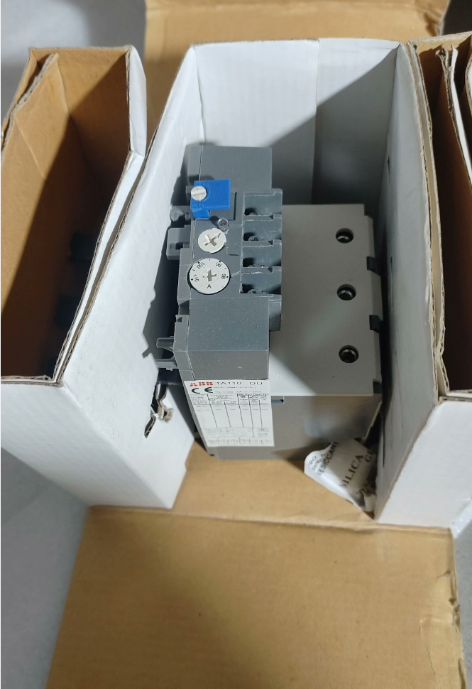

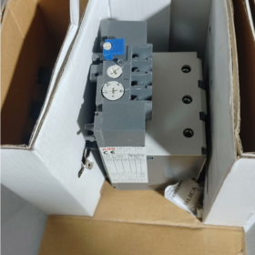
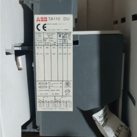
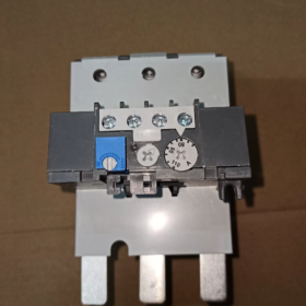
The TA110DU110 is a classic 3-pole 열 과부하 릴레이 ~에서 씨줄 TA 시리즈, delivering integrated protection for three-phase asynchronous motors with a rated current range of 80~110A. Adopting the inverse-time tripping principle of bimetallic strips, this relay comes standard with phase-loss protection and automatic ambient temperature compensation, with a trip class of Class 10A. It can be directly plugged onto ABB A/AE/AF95~110 series contactors or mounted independently on DIN rails. Equipped with switchable manual/automatic reset modes and one normally open (아니요) plus one normally closed (NC) auxiliary signal contact, it serves as a standard protective component for industrial motor control circuits. Widely applied to power loads such as fans, 물 펌프, compressors and conveyor lines, it effectively prevents winding burnout accidents of motors caused by overload, locked rotor and phase loss.
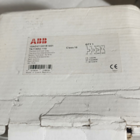
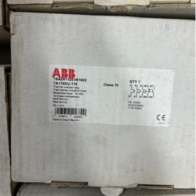
전체 모델: `TA110DU110`
- 깃 달기: General series code for ABB thermal overload relays, representing the family of electrothermal protective relays
- 110: 프레임 전류 정격, indicating the maximum rated frame current of 110A for this product
- 의: 기능 유형 코드, standing for standard specification featuring 3-pole protection, 위상 손실 감지, ambient temperature compensation and direct mounting onto contactors
- 110: Upper limit of current setting, corresponding to an adjustable current range of 80A ~ 110A
핵심 기술 사양
| 매개변수 카테고리 | 매개변수 항목 | 상세사양 |
| Main Circuit Characteristics | 정격 절연 전압 Ui | 690뷔와 / 440DC에서 |
| UL/CSA Rated Operational Voltage | 600뷔와 | |
| 조정 가능한 전류 범위 | Continuously adjustable from 80A to 110A | |
| 여행 클래스 | 클래스 10A (standard motor protection class) | |
| 극 수 | 3 극, full 3-pole protection | |
| 위상 손실 보호 | Standard built-in; accelerates tripping under three-phase unbalance | |
| 온도 보상 | 지원됨; protection accuracy remains unaffected within -25℃ ~ +55℃ ambient temperature | |
| 보조 연락처 | 연락처 구성 | 1 아니요 + 1 NC, 전기적으로 절연된 |
| Conventional Thermal Current Ith | 5에이 | |
| Rated Contact Capacity | AC250V 3A; DC24V 5A | |
| 기계 & 설치 | 장착 방법 | Direct mounting on contactors / independent DIN rail mounting |
| 호환 가능한 접촉기 | Series A95, A110, AE95, AE110, AF95, AF110 | |
| 배선 방법 | 나사 클램프 단자 | |
| 전체 중량 | 대략. 0.76kg | |
| 재설정 모드 | Switchable manual/automatic reset; supports remote reset expansion | |
| 환경 & 인증 | 작동 주변 온도 | -25℃ ~ +55℃ |
| 보관 온도 | -40℃ ~ +70℃ | |
| 침투 보호 등급 | IP20 | |
| 규정 준수 인증 | CE, UL, CSA, CCC, GL (Germanischer Lloyd Marine Certification) | |
| 준수 표준 | IEC 60947-4-1, 안에 60947-4-1 |
Cross Reference of Models within the Same Series
- Full Specifications of TA110DU Frame
| 전체 모델 | 조정 가능한 전류 범위 | 호환 가능한 모터 전력 (380다섯) | Matching Contactors |
| TA110DU-65 | 50 ~ 65A | 30kW | A95/AE95/AF95 |
| TA110DU-80 | 60 ~ 80A | 37kW | A95/AE95/AF95 |
| TA110DU-90 | 66 ~ 90A | 45kW | A110/AE110/AF110 |
| TA110DU-110 | 80 ~ 110A | 55kW | A110/AE110/AF110 |
- Comparison of Adjacent Frame Series
| 시리즈 모델 | Frame Rated Current | Maximum Adjustable Current | 적용 가능한 시나리오 |
| TA110DU | 110에이 | 110에이 | 중간 & small power motors (30~55kW) |
| TA200DU | 200에이 | 200에이 | 중간 & large power motors (75~110kW) |
| TA450DU | 450에이 | 450에이 | High-power heavy-duty motors (132~250kW) |
일반적인 애플리케이션 시나리오
- Standard Motor Starter Protection Circuit: Combined with ABB A/AF series contactors to form electromagnetic starters, connected in series to the main circuit of three-phase motors to realize protection against motor overload, locked rotor and phase loss. It is the standard protection solution for general power equipment including fans, 물 펌프, air compressors and machine tool spindles.
- MCC Motor Control Centers: Served as standard protection units for motor feeder circuits in drawer cabinets and fixed cabinets, integrated with contactors to realize integrated motor start-stop control and protection.
- 컨베이어 & Logistics Sorting Systems: Matched with roller motors and sorting drive motors, adapting to frequent start-stop and load fluctuation working conditions of production lines, and preventing motor aging and burnout caused by long-term overload.
- Central Air Conditioning & Refrigeration Units: Protect refrigeration power equipment such as compressors and cooling tower fans, suited to the refrigeration industry’s characteristics of severe load fluctuations and seasonal high-load operation.
- Support for OEM Complete Equipment: Widely matched with industrial machinery including packaging machinery, 고무 & plastic machinery and metallurgical auxiliary equipment. As standardized motor protection components, it meets electrical safety specification requirements for equipment factory delivery.
일반적인 문제 해결 매트릭스
| 결함 현상 | 근본 원인 분석 | 단계별 솔루션 |
| Relay falsely trips during normal motor operation | 1. Low current setting value, lower than the motor rated current | 1. Check the motor rated current and adjust the setting knob to the corresponding rated value |
| 2. Excessively high ambient temperature exceeding compensation range | 2. Improve cabinet heat dissipation and avoid direct sunlight or heat source radiation | |
| 3. Severe current deviation induced by three-phase voltage unbalance | 3. Measure three-phase currents to troubleshoot hidden risks of voltage unbalance or phase loss | |
| 4. Overlong motor startup time exceeding withstand limit of Class 10 여행 클래스 | 4. Replace with thermal overload relays of Class 20 또는 수업 30 for heavy-load startup applications | |
| Relay fails to trip under motor overload or locked rotor | 1. Excessively high current setting value, far higher than the motor rated current | 1. Recalibrate the setting value to strictly match the motor rated current |
| 2. Loose main circuit wiring terminals leading to excessive contact resistance | 2. Tighten main circuit terminals and troubleshoot overheating & oxidation issues | |
| 3. Stuck relay mechanical mechanism and failed tripping assembly | 3. Cut off power and manually test the flexibility of the tripping mechanism; replace the module if jamming occurs | |
| Protection does not activate upon phase loss fault | 1. Wrong three-phase incoming wiring with incomplete connection to relay main circuit | 1. Verify L1/L2/L3 three-phase wiring to ensure all phases are reliably connected |
| 2. Aging and failure of internal bimetallic components | 2. Artificially simulate phase loss to test protection function; replace the relay if function fails | |
| Abnormal or no output of auxiliary contact signals | 1. Auxiliary contact load exceeds rated capacity, resulting in contact burnout | 1. Confirm load current does not exceed contact rating; add intermediate relays for current amplification if necessary |
| 2. No reset after tripping, contacts remain in fault state | 2. Manually or automatically reset the relay after troubleshooting root fault causes | |
| 3. Poor contact due to contact oxidation | 3. Measure contact on-off resistance; replace the module if poor contact exists |
- 터미널 정의 & 기능 설명
The TA110DU110 adopts industry-standard terminal numbering rules, divided into two parts: main power circuit and auxiliary control circuit. All terminals are front-mounted screw-clamp type with all wiring operations accessible from the front side.
- 주회로 단자 (Three-Phase Power Circuit)
| 터미널 마크 | 터미널 유형 | 배선 지침 |
| 1L1, 3L2, 5L3 | 들어오는 터미널 | Upper-side input, connected to output terminals of contactor main contacts, corresponding to three-phase power L1/L2/L3 |
| 2T1, 4T2, 6T3 | 나가는 터미널 | Lower-side output, directly connected to stator windings of three-phase asynchronous motors |
메모: The three-phase main circuit has no polarity requirement, yet each phase must be connected in one-to-one correspondence without cross-phase misconnection. When directly mounted on contactors, the main circuit is automatically conducted via plug-in copper bars with no extra power wiring required.
- Auxiliary Circuit Terminals (제어 & Signal Circuit)
| 터미널 마크 | 연락 유형 | 기능 설명 | Typical Wiring Purpose |
| 95 – 96 | 평상시 닫힘 (NC) | Conductive under normal operating conditions; opens upon tripping caused by overload/phase loss | Connected in series to contactor coil control circuit to cut off power supply to the contactor and stop the motor upon faults |
| 97 – 98 | 평상시 열림 (아니요) | Disconnected under normal operating conditions; closes upon tripping caused by overload/phase loss | Connected to sound-light alarm circuits or PLC digital input points for fault signal upload and alarm notification |
The auxiliary contacts are electrically isolated with no electrical connection to the main circuit and a conventional thermal current of 5A. Intermediate relays are recommended for series connection to expand capacity and prevent contact burnout when controlling high-power loads.
- Typical Wiring Schemes
- Direct Mounting Wiring on Contactor (가장 일반적으로 사용되는)
This is the standard application method for TA110DU110. It is directly plugged onto the top of ABB A95/A110/AF95/AF110 series contactors. The main circuit is automatically connected through internal plug-in connectors, with only the control circuit requiring external wiring:
- Three-phase power passes through a circuit breaker and connects to contactor main incoming terminals L1/L2/L3
- After the thermal overload relay is directly mounted on the contactor, the main circuit is automatically conducted without extra power wiring
- One end of the control power supply passes through stop and start buttons and connects to contactor coil terminal A1
- 그만큼 95-96 NC contact of the thermal relay is connected in series to the live wire of the contactor coil circuit to realize automatic motor shutdown under overload
- 그만큼 97-98 NO contact of the thermal relay is paralleled with fault indicator lights or connected to PLC DI points for fault alarming
- Independent DIN Rail Mounting Wiring
Independent rail mounting is adopted for separate installation or matching with contactors of other brands:
- Contactor output terminals L1/L2/L3 are connected to thermal relay incoming terminals 1L1/3L2/5L3 via power cables
- Thermal relay outgoing terminals 2T1/4T2/6T3 connect to motor three-phase terminals
- The control circuit follows the same wiring logic as the direct mounting scheme, 와 함께 95-96 NC contact wired in series into the contactor coil circuit
배선상의 주의사항:
The cross-sectional area of main circuit cables shall match the 110A rated current; 25mm² copper cables are recommended
1~1.5mm² control cables are suggested for auxiliary control circuits
Reliable earthing is mandatory to guarantee personal and equipment safety
III. Parameter Comparison Table of Cross-Brand Equivalent Models
Below is a parameter comparison of mainstream thermal overload relays of the same current range from Siemens and Schneider Electric, for reference during alternative selection:
| 비교항목 | 씨줄 | 슈나이더 일렉트릭 | 지멘스 |
| 전체 모델 | TA110DU110 | LRD3365C | 3RU5146-4MB1 |
| 조정 가능한 전류 범위 | 80 ~ 110A | 80 ~ 104A | 80 ~ 100A |
| Frame Rated Current | 110에이 | 115에이 | 140에이 |
| 여행 클래스 | 클래스 10A | 수업 10 | 수업 10 |
| 극 수 | 3 극 | 3 극 | 3 극 |
| 보조 접점 구성 | 1아니요 + 1NC (전기적으로 절연된) | 1아니요 + 1NC (전기적으로 절연된) | 1아니요 + 1NC (전기적으로 절연된) |
| 위상 손실 보호 | Standard built-in | Standard built-in | Standard built-in |
| 주변 온도 보상 | 지원됨 (-25℃~+55℃) | 지원됨 (-20℃~+60℃) | 지원됨 (-20℃~+60℃) |
| 재설정 모드 | Switchable manual/automatic | Switchable manual/automatic | Switchable manual/automatic |
| Compatible Contactor Series | A95~A110, AF95~AF110 | LC1D95~LC1D115 | 3RT5045~3RT5046 |
| 장착 방법 | Direct mounting on contactor / DIN 레일 | Direct mounting on contactor / DIN 레일 | Direct mounting on contactor / DIN 레일 |
| 규정 준수 인증 | CE, UL, CCC, GL | CE, UL, CCC | CE, UL, CCC |


 Impulse Heat-Sealing Temperature Controller")


")


NH42-63-318x560.png "CHINT PC형 자동절환스위치 (ATS)NH42-63/4SZ")


