 접촉기,회로 차단기,태양광 인버터,전기 계량기,태양 전지

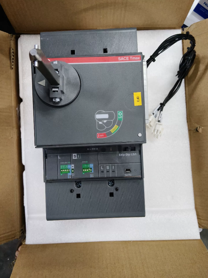

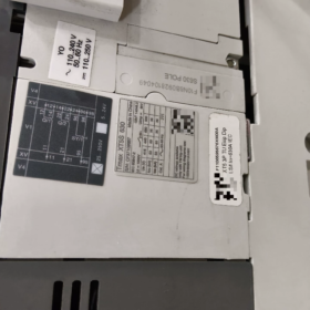
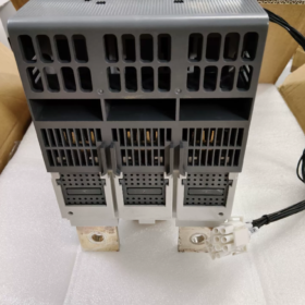
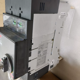
그만큼 씨줄 XT5S 630 is an S-breaking capacity MCCB with a 630A frame size from ABB’s Tmax XT low-voltage moulded case circuit breaker series. It is mainly used for overload and short-circuit protection in AC low-voltage power distribution systems. Featuring a compact footprint and high short-circuit breaking capacity, it supports multiple trip unit configurations including thermal-magnetic and electronic types. Widely applied in industrial power distribution, building power supply, data centers and other scenarios, it complies with IEC 60947-2 및 GB/T 14048.2 표준.
- Full Breakdown of Model Coding
Basic Model Definition
XT5 S 630
- XT5: Frame code of Tmax XT series, frame rated current ranges from 400A to 630A
- 에스: Short-circuit breaking capacity class; ultimate short-circuit breaking capacity Icu = 50kA at 415V AC
- 630: Frame rated current of 630A; trip unit rated current In can be selected within the frame current range
Explanation of Full Suffix Model
Take the mainstream model `XT5S 630 Ekip Dip LS/I In=630 3p F F` as an example:
Ekip Dip: Economical electronic trip unit without display panel, adjusted via DIP switches
LS/I: Combined protection functions: 엘 (long-time overload protection) + 에스 (short-time short-circuit protection) + 나 (순간 단락 보호) (3-무대 보호)
In=630: Trip unit rated operating current 630A
3피: 3-폴; 4-폴 (4피) 선택 사항입니다
에프에프: 설치 & 배선 유형; the first F stands for fixed mounting, the second F for front wiring
- 핵심 기술 매개변수
- 전기적 성능 매개변수
| 매개변수 항목 | 사양 값 | 비고 |
| Frame Rated Current Iu | 630에이 | Maximum frame rating |
| Trip Unit Rated Current In | 315에이 / 400에이 / 500에이 / 630에이 | Multiple ratings available, matching corresponding trip unit models |
| 정격 작동 전압 Ue | AC 220V~690V, 50/60헤르츠 | Applicable for full voltage range |
| Ultimate Short-Circuit Breaking Capacity Icu | 415뷔와: 50그만큼 | Standard value for Class S |
| 690뷔와: 25그만큼 | ||
| 250DC에서: 35그만큼 (2 poles in series) | ||
| Service Short-Circuit Breaking Capacity Ics | 415뷔와: 50그만큼 | IC = 100% 중환자실, reusable after fault interruption |
| 보호 기능 | Long-time overload, short-time short-circuit, 순간 단락, 지락 (선택 과목) | Varies by trip unit type |
| 기계적 내구성 | 20,000 작동주기 | 정격 조건에서 |
| 작동 주파수 | 240 주기/시간 | Rated frequency for electrical operation |
- 기계 & 물리적 매개변수
Unit weight: 대략. 5.6kg (3-pole fixed type)
Mounting types: 결정된, 플러그인, 인출 가능
Wiring types: 전면배선, 후면 배선, plug-in busbar connection
보호등급: IP20 for the main body; upgradable to IP40 with terminal covers
III. Comparison of Breaking Capacity Classes for XT5 Frame
Parameter differences between breaking capacity classes under the same frame size for easy capacity upgrade or downgrade:
| Breaking Class | 암호 | Icu at 415V AC | 일반적인 애플리케이션 시나리오 |
| 기초적인 | N | 36그만큼 | 토목 건물, terminal distribution circuits |
| 기준 | 에스 | 50그만큼 | 산업 플랜트, main incoming cabinets, general power circuits |
| 높은 속보 | 시간 | 70그만큼 | Low-voltage side of large-capacity transformers, systems with high short-circuit current |
- Selection of Mainstream Trip Unit Configurations
The XT5S 630 supports two types of trip units: thermal-magnetic and electronic, to meet diverse protection requirements:
| 트립 유닛 유형 | 모델 코드 | 보호 기능 | 조정 방법 | 응용 시나리오 |
| 열-자기 트립 장치 | TMA | 2-무대 보호: L long-time + I instantaneous | 회전식 손잡이 / DIP switch | 일반 전력 분배, 모터 보호, 비용 효율적 |
| Economical Electronic Trip Unit | Ekip Dip | 3-stage LS/I protection | 딥 스위치 | Distribution systems requiring selective coordination between upstream and downstream devices |
| High-End Intelligent Trip Unit | Ekip Touch | 4-stage LSIG protection + 에너지 계량 | Touch buttons + display screen | Intelligent power distribution, scenarios requiring fault recording and energy monitoring |
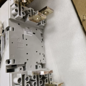
- 장착 유형 & 배선사양
- 장착 유형
결정된 (FF/FR): 전면/후면 배선, directly fixed by screws, 최저 비용, for fixed distribution cabinets
플러그인 (PMP): Busbar plug-in installation, supports quick replacement, for drawer-type switchgear
Withdrawable (WMP): Equipped with racking mechanism, clear isolation breakpoints, for main circuits requiring frequent maintenance
- Cable Wiring Specifications (Copper Cable Reference)
In=630A: 추천 2 parallel single-core 240mm² copper cables, or 60×6mm copper busbar
In=500A: 추천 1 single-core 300mm² copper cable, or 50×5mm copper busbar
- 브랜드 간 동등 모델 비교
Reference mainstream alternative models with identical 630A frame size and 50kA breaking capacity:
| 상표 | 동등한 모델 | 프레임 전류 | Breaking Capacity at 415V AC | 호환성 설명 |
| 슈나이더 일렉트릭 | NSX630S | 630에이 | 50그만큼 | 기능적으로 동일함; different mounting cutout dimensions requiring cabinet modification |
| 지멘스 | 3VL630S | 630에이 | 50그만큼 | Consistent protection performance; terminal specifications differ |
| 친트 | NM1-630S | 630에이 | 50그만큼 | 비용 효율적인 국내 대안; non-interchangeable mounting dimensions |
Ⅶ. 일반적인 애플리케이션 시나리오
- Main incoming switches and bus tie couplers for low-voltage distribution systems
- Main circuit protection for high-capacity power loads (물 펌프, 팬, 압축기)
- Power distribution protection for industrial production lines, data centers and commercial complexes
- DC side protection for new energy systems such as photovoltaic and energy storage (with dedicated DC trip unit as an option)
Ⅷ. Common Fault Handling Matrix
| 결함 카테고리 | Typical Fault Phenomenon | 근본 원인 분석 | 단계별 솔루션 |
| Mechanical Operation Faults | Circuit breaker cannot close; handle rebounds immediately after release when pushed toward ON | 1. Incomplete reset after fault tripping (most common cause) | 1. Firmly pull the handle fully down to the lowest OFF position until a clicking reset sound is heard, then close the breaker |
| (Most Frequent On-Site) | 2. Undervoltage trip coil unpowered / insufficient voltage locking the mechanism | 2. Measure supply voltage of undervoltage coil to confirm compliance with rated value | |
| 3. Locked external electrical or mechanical interlocks | 3. Inspect external signals including cabinet door interlock and fire interlock, then release locks | ||
| 4. Contact welding and mechanism jamming after short-circuit interruption | 4. If contact welding is confirmed, do not force closing; replace the entire breaker directly | ||
| 무거운, stuck handle operation with unsmooth gear switching | 1. Mechanism clogged by dust and grease, insufficient lubrication on rotating shafts | 1. Clean dust inside the mechanism and apply a small amount of insulating grease to rotating shafts | |
| 2. Cabinet deformation squeezing the casing and offsetting the mechanism | 2. Adjust mounting screws to eliminate casing stress | ||
| 3. Interference from external handle extension or protective cover | 3. Remove outer cover for testing and correct interference positions | ||
| Abnormal Unintentional Tripping | Unprovoked tripping under light load or no load with no obvious short-circuit fault | 1. Long-time protection setting lower than actual operating current | 1. Verify actual load current and reset long-time current gear |
| (Highest User Complaint Rate) | 2. Ambient temperature over 40掳C causing thermal drift of thermal-magnetic trip unit and premature tripping | 2. Select models with derating coefficients for high-temperature environments or upgrade to a higher rated current frame | |
| 3. Severe system harmonic current inducing extra conductor heating and triggering protection | 3. Mitigate system harmonics by installing reactors or active power filters | ||
| 4. Aging trip unit components with parameter drift | 4. Replace trip unit if severe thermal drift occurs on thermal-magnetic types | ||
| Instant tripping upon startup of motors or inverters | 1. Too low instantaneous protection setting unable to withstand startup inrush current | 1. Adjust instantaneous protection multiplier to 8~10In for motor circuits | |
| 2. Too short short-time protection delay with no margin for startup transients | 2. Enable short-time delay function and set 0.1~0.4s delay to bypass startup peak current | ||
| 3. Motor-specific trip unit is recommended for dedicated motor circuits | |||
| Frequent earth fault tripping on models with earth fault protection | 1. Total normal leakage current of the system exceeds protection setting | 1. Measure actual system leakage current and moderately raise earth fault trip threshold | |
| 2. Incorrect N-line wiring or reversed polarity on 4-pole breakers | 2. Correct N-line wiring to ensure it passes through the zero-sequence CT | ||
| 3. Zero-sequence CT installed at wrong position | 3. Install zero-sequence CT in accordance with manual specifications | ||
| Trip Unit Malfunction | Black screen and unresponsive buttons on Ekip Touch electronic trip unit | 1. Auxiliary control power supply disconnected or lost | 1. Check auxiliary power wiring and voltage rating (AC220V / DC24V, 등.) |
| 2. Loose plug connection between trip unit module and main body | 2. Replug trip unit module after power cut-off to ensure full pin contact | ||
| 3. Damaged electronic components inside trip unit | 3. Replace trip unit of identical model if module is damaged | ||
| DIP switch-type Ekip Dip trip unit fails to apply adjusted parameters | 1. DIP switches not fully locked at critical positions | 1. Toggle DIP switches after power cut-off and confirm each gear is fully engaged | |
| 2. Poor contact of trip unit current transformers | 2. Reinstall trip unit to ensure tight fit between CT and main body | ||
| No fault indication or stored records after fault tripping | 1. Loss of auxiliary power to trip unit causing fault data loss | 1. Constant auxiliary power supply is recommended for trip units on critical circuits | |
| 2. Stuck mechanical fault indicator not popping out | 2. Manually reset indicator mechanism and inspect linkage parts | ||
| 종범 & Auxiliary Circuit Faults | Shunt trip and undervoltage trip coils fail to actuate | 1. Mismatch between coil rated voltage and supply voltage | 1. Check coil voltage label and replace with matching specification |
| 2. Loose wiring or open circuit from burnt coil | 2. Measure coil continuity with multimeter; replace coil if burnt | ||
| 3. Insufficient stroke of coil push rod unable to trigger mechanism | 3. Adjust coil mounting position to guarantee adequate push rod stroke | ||
| Incorrect signal and poor contact of auxiliary contacts | 1. Worn and oxidized silver contact points of auxiliary contacts | 1. 보조 접점 모듈 교체 | |
| 2. Offset linkage lever causing incomplete contact switching | 2. Adjust linkage mechanism position to ensure reliable contact switching during closing and opening | ||
| 과열 & 배선 결함 | Overheated incoming/outgoing terminals, hot casing with peculiar odor | 1. Terminal screws not tightened to specified torque leading to excessive contact resistance | 1. Retighten terminals to manufacturer-specified torque (대략. 25~30N路m for 630A terminals) |
| 2. Insufficient cable cross-section causing long-term overload heating | 2. Replace with larger cross-section cables or add more parallel cables | ||
| 3. Uneven cable length among parallel cables resulting in unbalanced current distribution | 3. Ensure parallel cables have identical length, specification and terminals | ||
| 4. Direct copper-aluminum connection triggering electrochemical corrosion | 4. Install copper-aluminum transition lugs; direct copper-aluminum connection is prohibited | ||
| Overall overheating of breaker casing | 1. Long-term operation exceeding rated current | 1. Restrict load current or upgrade to a larger frame size | |
| 2. Poor cabinet ventilation and excessive ambient temperature | 2. Add cabinet cooling fans to improve ventilation | ||
| 3. Worn main contacts leading to increased contact resistance | 3. Replace the whole breaker if contact resistance exceeds standard limits | ||
| Post Short-Circuit Interruption Faults | Cannot close breaker after interrupting short-circuit fault; mechanism locked | 1. System short-circuit current exceeds breaker rated breaking capacity, causing contact welding | 1. Verify system short-circuit current and replace with higher breaking class (예를 들어. 클래스 H) 모델 |
| 2. Mechanism deformed by impact and stuck trip shaft | 2. Replace the entire breaker if mechanism is damaged; disassembly and repair are forbidden | ||
| Reduced insulation and cabinet leakage after fault interruption | 1. Arc ablation of arc chamber generates carbide deposits on insulating parts | 1. Remove detachable arc chamber, clean carbon powder and reinstall after full drying | |
| 2. Internal insulating partition damaged by arc burning | 2. Replace the whole breaker if insulating components are damaged |
일반적인 결함 & Solutions for ABB XT5S 630
Field faults of the ABB XT5S 630 MCCB mainly fall into four categories: mechanical operation faults, abnormal tripping, accessory failure and excessive temperature rise. Most issues arise from improper installation & 환경, unsuitable operating environment or lack of routine maintenance, while inherent factory defects of the unit are rare. Below is a full summary of frequent faults and corresponding resolutions:
Common Fault Handling Matrix
| 결함 카테고리 | Typical Fault Phenomenon | 근본 원인 분석 | 단계별 솔루션 |
| Mechanical Operation Faults | Circuit breaker cannot close; handle rebounds immediately after release when pushed toward ON | 1. Incomplete reset after fault tripping (most common cause) | 1. Firmly pull the handle fully down to the lowest OFF position until a clicking reset sound is heard, then close the breaker |
| (Most Frequent On-Site) | 2. Undervoltage trip coil unpowered / insufficient voltage locking the mechanism | 2. Measure supply voltage of undervoltage coil to confirm compliance with rated value | |
| 3. Locked external electrical or mechanical interlocks | 3. Inspect external signals including cabinet door interlock and fire interlock, then release locks | ||
| 4. Contact welding and mechanism jamming after short-circuit interruption | 4. If contact welding is confirmed, do not force closing; replace the entire breaker directly | ||
| 무거운, stuck handle operation with unsmooth gear switching | 1. Mechanism clogged by dust and grease, insufficient lubrication on rotating shafts | 1. Clean dust inside the mechanism and apply a small amount of insulating grease to rotating shafts | |
| 2. Cabinet deformation squeezing the casing and offsetting the mechanism | 2. Adjust mounting screws to eliminate casing stress | ||
| 3. Interference from external handle extension or protective cover | 3. Remove outer cover for testing and correct interference positions | ||
| Abnormal Unintentional Tripping | Unprovoked tripping under light load or no load with no obvious short-circuit fault | 1. Long-time protection setting lower than actual operating current | 1. Verify actual load current and reset long-time current gear |
| (Highest User Complaint Rate) | 2. Ambient temperature over 40掳C causing thermal drift of thermal-magnetic trip unit and premature tripping | 2. Select models with derating coefficients for high-temperature environments or upgrade to a higher rated current frame | |
| 3. Severe system harmonic current inducing extra conductor heating and triggering protection | 3. Mitigate system harmonics by installing reactors or active power filters | ||
| 4. Aging trip unit components with parameter drift | 4. Replace trip unit if severe thermal drift occurs on thermal-magnetic types | ||
| Instant tripping upon startup of motors or inverters | 1. Too low instantaneous protection setting unable to withstand startup inrush current | 1. Adjust instantaneous protection multiplier to 8~10脳In for motor circuits | |
| 2. Too short short-time protection delay with no margin for startup transients | 2. Enable short-time delay function and set 0.1~0.4s delay to bypass startup peak current | ||
| 3. Motor-specific trip unit is recommended for dedicated motor circuits | |||
| Frequent earth fault tripping on models with earth fault protection | 1. Total normal leakage current of the system exceeds protection setting | 1. Measure actual system leakage current and moderately raise earth fault trip threshold | |
| 2. Incorrect N-line wiring or reversed polarity on 4-pole breakers | 2. Correct N-line wiring to ensure it passes through the zero-sequence CT | ||
| 3. Zero-sequence CT installed at wrong position | 3. Install zero-sequence CT in accordance with manual specifications | ||
| Trip Unit Malfunction | Black screen and unresponsive buttons on Ekip Touch electronic trip unit | 1. Auxiliary control power supply disconnected or lost | 1. Check auxiliary power wiring and voltage rating (AC220V / DC24V, 등.) |
| 2. Loose plug connection between trip unit module and main body | 2. Replug trip unit module after power cut-off to ensure full pin contact | ||
| 3. Damaged electronic components inside trip unit | 3. Replace trip unit of identical model if module is damaged | ||
| DIP switch-type Ekip Dip trip unit fails to apply adjusted parameters | 1. DIP switches not fully locked at critical positions | 1. Toggle DIP switches after power cut-off and confirm each gear is fully engaged | |
| 2. Poor contact of trip unit current transformers | 2. Reinstall trip unit to ensure tight fit between CT and main body | ||
| No fault indication or stored records after fault tripping | 1. Loss of auxiliary power to trip unit causing fault data loss | 1. Constant auxiliary power supply is recommended for trip units on critical circuits | |
| 2. Stuck mechanical fault indicator not popping out | 2. Manually reset indicator mechanism and inspect linkage parts | ||
| 종범 & Auxiliary Circuit Faults | Shunt trip and undervoltage trip coils fail to actuate | 1. Mismatch between coil rated voltage and supply voltage | 1. Check coil voltage label and replace with matching specification |
| 2. Loose wiring or open circuit from burnt coil | 2. Measure coil continuity with multimeter; replace coil if burnt | ||
| 3. Insufficient stroke of coil push rod unable to trigger mechanism | 3. Adjust coil mounting position to guarantee adequate push rod stroke | ||
| Incorrect signal and poor contact of auxiliary contacts | 1. Worn and oxidized silver contact points of auxiliary contacts | 1. 보조 접점 모듈 교체 | |
| 2. Offset linkage lever causing incomplete contact switching | 2. Adjust linkage mechanism position to ensure reliable contact switching during closing and opening | ||
| 과열 & 배선 결함 | Overheated incoming/outgoing terminals, hot casing with peculiar odor | 1. Terminal screws not tightened to specified torque leading to excessive contact resistance | 1. Retighten terminals to manufacturer-specified torque (대략. 25~30N路m for 630A terminals) |
| 2. Insufficient cable cross-section causing long-term overload heating | 2. Replace with larger cross-section cables or add more parallel cables | ||
| 3. Uneven cable length among parallel cables resulting in unbalanced current distribution | 3. Ensure parallel cables have identical length, specification and terminals | ||
| 4. Direct copper-aluminum connection triggering electrochemical corrosion | 4. Install copper-aluminum transition lugs; direct copper-aluminum connection is prohibited | ||
| Overall overheating of breaker casing | 1. Long-term operation exceeding rated current | 1. Restrict load current or upgrade to a larger frame size | |
| 2. Poor cabinet ventilation and excessive ambient temperature | 2. Add cabinet cooling fans to improve ventilation | ||
| 3. Worn main contacts leading to increased contact resistance | 3. Replace the whole breaker if contact resistance exceeds standard limits | ||
| Post Short-Circuit Interruption Faults | Cannot close breaker after interrupting short-circuit fault; mechanism locked | 1. System short-circuit current exceeds breaker rated breaking capacity, causing contact welding | 1. Verify system short-circuit current and replace with higher breaking class (예를 들어. 클래스 H) 모델 |
| 2. Mechanism deformed by impact and stuck trip shaft | 2. Replace the entire breaker if mechanism is damaged; disassembly and repair are forbidden | ||
| Reduced insulation and cabinet leakage after fault interruption | 1. Arc ablation of arc chamber generates carbide deposits on insulating parts | 1. Remove detachable arc chamber, clean carbon powder and reinstall after full drying | |
| 2. Internal insulating partition damaged by arc burning | 2. Replace the whole breaker if insulating components are damaged |
Key Points for Fault Prevention & 정기 유지 관리
- Tighten wiring terminals strictly to rated torque before commissioning; contact resistance testing is recommended for high-current circuits.
- Select derated capacity in advance for environments with high temperature, high humidity or heavy dust; regularly clean dust accumulated on the breaker surface.
- Constant auxiliary power supply is suggested for electronic trip unit circuits to avoid loss of fault records.
- Perform at least one mechanical operation test annually to verify smooth closing and opening; manual opening under heavy load is prohibited.
- Inspect contact condition after every short-circuit interruption; replace the whole unit promptly upon reaching electrical service life limit.


 슈나이더 TeSys GV2 시리즈. 24-32A의 조정 가능한 전류 설정이 특징입니다.,")

")


NH42-63-318x560.png "CHINT PC형 자동절환스위치 (ATS)NH42-63/4SZ")


