 접촉기,회로 차단기,태양광 인버터,전기 계량기,태양 전지

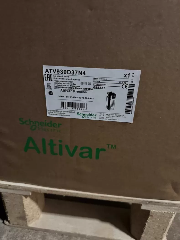


The ATV930D37N4 is a high-end standard variable speed drive ~에서 슈나이더 일렉트릭’s Altivar Process ATV900 series, 공정 산업을 위해 설계됨. 정격 정상 출력은 37kW이고 중부하 출력은 30kW입니다., compatible with 3-phase 380~480V power grids. It comes with an integrated braking chopper and EMC filter as standard, with an IP21 enclosure rating. Optimized for continuous operating conditions such as fans, 물 펌프, 운반 시스템, agitators and compressors, this unit integrates process PID, 다중 펌프 제어, energy optimization and industrial fieldbus communication functions. It is widely used in water treatment, 기름 & 가스, 음식 & 음료, 채광, metallurgy and other industries, complying with international standards including IEC 61800 and UL 508C.
- Full Breakdown of Model Coding
Definition of Basic Model Markings
ATV 930 D37 N4
- ATV: Prefix for Altivar series, universal identifier for Schneider variable speed drives
- 930: Standard sub-series of the ATV900 Process range, positioned as a general-purpose drive for process industries, supporting asynchronous and synchronous motor control
- D37: Power rating code; matched to 37kW motors under Normal Duty and 30kW motors under Heavy Duty
- N4: Voltage and configuration class, representing 3-phase 380~480V AC input, 50/60헤르츠, built-in Class C2 EMC filter and standard integrated braking chopper
Extended Explanation of Full Model Suffixes
A typical complete order code is `ATV930D37N4Z`. Suffix letters indicate additional configurations:
접미사 없음: Standard unit equipped with Chinese graphical display panel and integrated braking unit
지: Cost-optimized version with simplified operator panel
Specific letter suffixes correspond to dedicated firmware (for pump, fan and crane applications)
- 핵심 기술 사양
- 전기적 성능 매개변수
| 매개변수 항목 | 사양 값 | 비고 |
| 정격 입력 전압 | 3-phase 380~480V AC, -15%~+10%, 50/60헤르츠±5% | Adaptable to wide-voltage power grids |
| 정격 출력 전력 (일반 근무) | 37kW (50HP) | For variable-torque / light constant-torque applications |
| 정격 출력 전력 (헤비 듀티) | 30kW (40HP) | For heavy constant-torque and shock-load applications |
| 정격 출력 전류 (일반 근무) | 74.5에이 (4kHz switching frequency) | Nominal value under 400V grid |
| 정격 출력 전류 (헤비 듀티) | 61.5에이 (4kHz switching frequency) | Nominal value under 400V grid |
| 과부하 기능 | 일반 근무: 120% 60초 동안 정격 전류 | Cycle length: 10 분 |
| 헤비 듀티: 150% rated current for 2s | ||
| 출력 주파수 범위 | 0.01Hz ~ 599Hz | Adjustable via parameter settings |
| 제어 모드 | V/F 제어, 센서리스 벡터 제어, closed-loop vector control (encoder optional), synchronous motor control | Compatible with asynchronous, permanent magnet synchronous (PMSM) and synchronous reluctance (SynRM) 모터 |
| 최고의 단락 차단 용량 | Matched with 125A fuse, withstands 50kA short-circuit current | Coordination value for upstream protection |
| 내장 기능 | Braking chopper unit, Class C2 EMC filter, PID regulator, STO 안전 기능 | Standard integration, no extra options required |
- 기계 & 물리적 매개변수
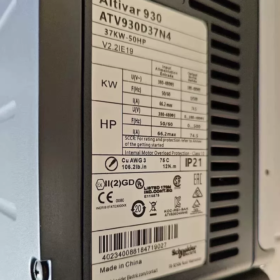
전체 치수 (폭 × 높이 × 깊이): 271mm × 673mm × 226mm
Total weight: 대략. 28.2kg
Enclosure rating: IP21 (IEC 60529) / UL Type 1, cabinet wall-mounted installation
냉각방식: Forced air cooling with intelligent variable-speed temperature-controlled fans
장착 유형: 수직 벽 장착, allowable tilt ±10°
주변 작동 온도: -15℃ ~ +50℃ (경감 없음); derating required for +50℃~+60℃
III. 핵심 기능 & 기술적 특징
- Motor Control Performance
Universal drive support for asynchronous motors, 영구자석 동기 모터 (PMSM) and Synchronous Reluctance Motors (SynRM) without hardware replacement
Delivers 180% rated torque at 0.5Hz under sensorless vector mode for stable low-speed torque output
Standard motor auto-tuning function to automatically identify motor parameters and optimize control accuracy
Adjustable switching frequency from 2kHz to 16kHz to balance heat generation and motor noise
- Dedicated Process Industry Functions
Built-in high-precision PID regulator supporting closed-loop control of pressure, flow, liquid level and temperature without external PLC
Multi-pump control function supporting up to 4 pumps for cyclic start/stop, fault switching and sleep/wake-up, suitable for constant-pressure water supply systems
Native flow compensation, sleep/wake and auto energy-saving modes, delivering 20%~40% comprehensive energy savings for fan and pump applications
Integrated fault recording and data log storage for the latest 10 fault records and operating waveforms to facilitate traceability analysis
- 안전 & 보호 기능
Standard STO (세이프 토크 오프) function achieving PL e / 실 3 safety level to comply with machinery safety requirements
Full-range electrical protection: 과전류, 과전압, 저전압, output short-circuit, 지락, motor overheating, drive overheating, output phase loss
Support for motor thermal protection model as an alternative to external thermal relays for precise motor temperature protection
- 의사소통 & Expansion Capabilities
Standard communication interfaces: 모드버스 RTU (RS485), CANopen
Expandable industrial fieldbuses: 프로피네트, 이더넷/IP, EtherCAT, 프로피버스 DP, BACnet/IP, 등.
3 reserved expansion slots for I/O modules, encoder interface modules and communication modules
Built-in web server supporting remote monitoring, parameter configuration and fault diagnosis via web pages
- 설치, 배선 & Supporting Selection
- Main Circuit Cable Specifications (Copper Cable Reference)
Input power cable: Recommended 25mm² copper power cable
Output motor cable: Recommended 25mm² copper power cable; output reactor advised for long-distance wiring
Recommended braking resistor: Matched for 37kW model, 15Ω resistance with 5kW power rating
- 설치 & 배선상의 주의사항
- 수직 장착; reserve a minimum 100mm ventilation gap top and bottom, and 50mm clearance on left and right sides
- Separate power cables and control cables with a spacing ≥200mm to avoid electromagnetic interference
- Reliable earthing of ground terminals with earthing resistance ≤4Ω; single-end grounding for cable shields
- 단자 조임 토크: 12~15N·m for main circuit terminals, 0.6~0.8N·m for control circuit terminals
- Common Fault Handling Matrix
| 오류 코드 | 결함 현상 | 근본 원인 분석 | 단계별 솔루션 |
| OHF | Drive trips with overheating alarm | 1. Damaged cooling fan / 막힌 공기 덕트 | 1. Inspect fan operation and clear dust from air ducts |
| 2. 과도한 주변 온도 | 2. 캐비닛 환기 개선; operate under derating at high temperatures | ||
| 3. Long-term overload operation | 3. Check load current and adjust overload parameters | ||
| 4. Excessively high switching frequency setting | 4. Appropriately lower the switching frequency setting | ||
| SCF1 / SCF3 | Motor short-circuit / earth short-circuit fault | 1. Damaged insulation of output cables with phase-to-ground leakage | 1. Cut power and disconnect motor cables; measure insulation resistance of cables and motor |
| 2. Short-circuited motor windings / inter-turn short circuit | 2. Inspect motor terminals and terminal box for water ingress or burn marks | ||
| 3. Loose terminals with copper wire burrs causing short circuits | 3. Verify motor parameters match the nameplate and re-run auto-tuning | ||
| OCF | Overcurrent trip during operation | 1. Too short acceleration time leading to large startup inrush | 1. Extend acceleration time parameters and reduce startup torque boost value |
| 2. Sudden load variation or mechanical jamming | 2. Rotate motor by hand to check mechanical load and bearing jamming | ||
| 3. Malfunction of current detection components | 3. Disconnect load for no-load testing to troubleshoot hardware detection circuits | ||
| OVF | Overvoltage trip during deceleration | 1. Too short deceleration time and high load inertia | 1. Extend deceleration time and enable DC braking function |
| 2. Mismatched braking resistor resistance / 느슨한 배선 | 2. Check braking resistor resistance and wiring; confirm braking unit is activated | ||
| 3. 지나치게 높은 그리드 전압 | 3. Monitor grid voltage; install input reactor if necessary | ||
| LF | Output phase loss alarm | 1. Open circuit on one phase of motor cable | 1. Test continuity of three phases of motor cable |
| 2. Poor contact from loose output terminals | 2. Tighten output terminals to specified torque | ||
| 3. Current unbalance caused by single-phase load | 3. Disable phase loss detection temporarily only for single-phase load commissioning (restore for formal operation) | ||
| Blank operator panel with no display after power-on | Operator panel remains dark and unresponsive after energization | 1. Input power phase loss / excessively low voltage | 1. Measure three-phase input voltage for normal values |
| 2. Internal switching power supply failure | 2. Cut power and re-plug operator panel connecting cable | ||
| 3. Loose operator panel cable causing poor contact | 3. Troubleshoot internal rectifier and switching power supply circuits |
- Power Model Comparison for the Same Series (ATV930 N4 Series, 380-480다섯)
| 모델 | 일반 의무 전력 | 헤비 듀티 파워 | 정격 출력 전류 (일반 근무) |
| ATV930D15N4 | 15kW | 11kW | 30.4에이 |
| ATV930D22N4 | 22kW | 18.5kW | 41.5에이 |
| ATV930D30N4 | 30kW | 22kW | 54.8에이 |
| ATV930D37N4 | 37kW | 30kW | 74.5에이 |
| ATV930D45N4 | 45kW | 37kW | 87에이 |
| ATV930D55N4 | 55kW | 45kW | 108에이 |
Ⅶ. Cross-Brand Equivalent Replacement Reference
| 상표 | 동등한 모델 | 정격 출력 | Key Difference Description |
| 씨줄 | ACS880-01-072A-3 | 37kW | Comparable functional positioning; different mounting dimensions and parameter architectures |
| 지멘스 | 6SL3210-1PE27-5UL0 (G120) | 37kW | Modular design with separate power unit and control unit; different cabinet compatibility |
| 혁신 | MD500T37G | 37kW | Cost-effective domestic alternative covering mainstream functions; non-interchangeable mounting dimensions |
일반적인 결함 & Troubleshooting Solutions for Schneider ATV930D37N4
As an engineering-grade drive from Schneider’s Altivar Process range, on-site faults of the ATV930D37N4 mainly fall into four categories: load matching, grid voltage fluctuation, heat dissipation conditions and parameter configuration. The inherent hardware failure rate of the unit itself is low. Below is a full summary of frequent on-site faults including official standard fault codes, fault phenomena, root cause analysis and step-by-step resolution procedures, compiled in accordance with Schneider official technical specifications and field maintenance practices.
- General Troubleshooting Matrix for High-Frequency Faults
- 과전류 & Short-Circuit Faults (Most Frequent On-Site; High-Voltage Circuit Inspection First)
| 오류 코드 | 결함 현상 | 근본 원인 분석 | 단계별 솔루션 |
| SCF1 | Instant trip upon startup or operation with motor short-circuit prompt on panel | 1. Damaged insulation of output cables leading to phase-to-phase short circuit | 1. Do NOT repeatedly reset and force startup; cut power and disconnect motor-side cables |
| Motor Phase-to-Phase Short Circuit | 2. Inter-turn short circuit of motor windings and burnt terminal box | 2. Measure phase-to-phase and phase-to-earth insulation resistance of U/V/W with a megohmmeter; normal value ≥5MΩ | |
| 3. Loose terminals with copper burrs causing phase-to-phase arcing | 3. Inspect motor terminal box and terminal strip for burn marks and copper debris short-circuits | ||
| 4. Mismatched motor parameters and control mode resulting in excessive startup inrush | 4. Verify motor nameplate parameters, re-run motor auto-tuning and reduce torque boost magnitude | ||
| 5. If false alarms persist with normal insulation, lower switching frequency to 2~4kHz appropriately | |||
| SCF3 | Earth fault trip immediately after power-on startup with abnormal output earth detection | 1. Single-phase earth damage on output cables | 1. Disconnect motor cables and measure insulation of cables and motor to earth separately |
| Motor Earth Short Circuit | 2. Breakdown of motor winding insulation to earth | 2. Install output reactor for long-distance wiring to suppress earth leakage current | |
| 3. Excessive leakage current due to large distributed capacitance of long cables | 3. Appropriately raise earth fault detection threshold for multi-motor parallel applications | ||
| 4. Total leakage current exceeding threshold when multiple motors are connected in parallel | 4. Confirm standardized earthing system with reliable common earthing for drive and motor | ||
| OCF | Trip upon sudden load variation with steady-state current exceeding rated value | 1. Sudden mechanical load jamming or seized bearings | 1. Cut power and rotate motor by hand to check smoothness of motor and load mechanical transmission |
| Overcurrent During Operation | 2. Overly short acceleration time causing startup inrush exceeding rated value | 2. Extend acceleration time parameters and reduce startup torque boost coefficient | |
| 3. Mismatched vector control parameters leading to current loop oscillation | 3. Re-run static/dynamic motor auto-tuning to correct control parameters | ||
| 4. Verify load power and confirm if undersized model was selected for heavy-duty applications |
- 과전압, 저전압 & Braking Faults
| 오류 코드 | 결함 현상 | 근본 원인 분석 | 단계별 솔루션 |
| OVF | Frequent trips during deceleration and shutdown with bus voltage exceeding 780V | 1. Overly short deceleration time, high load inertia and rapid energy feedback | 1. Extend deceleration time and enable DC braking function for auxiliary deceleration |
| DC 버스 과전압 | 2. Disabled built-in braking unit or mismatched braking resistor resistance/power | 2. Confirm braking unit parameters are activated and verify braking resistor resistance (15/5kW recommended for 37kW model) | |
| 3. Excessively high grid input voltage elevating baseline bus voltage | 3. Check for loose braking resistor wiring and measure resistance for normal values | ||
| 4. Monitor grid input voltage; install input reactor if voltage is excessively high | |||
| USF | Shutdown during grid fluctuations with bus voltage below threshold | 1. Aged contacts of upstream circuit breakers and contactors causing large contact voltage drop | 1. Measure three-phase input voltage to confirm if it drops below 320V (380V 시스템) |
| Input Undervoltage | 2. Grid voltage dip and voltage drop from simultaneous startup of large-capacity equipment | 2. Check tightening torque of incoming terminals and inspect oxidation of upstream switch contacts | |
| 3. Damaged internal rectifier bridge or degraded bus capacitor capacitance | 3. If alarm persists under steady normal voltage, measure DC bus voltage and troubleshoot rectifier and capacitor circuits | ||
| NLP | Only control indicator lit on panel with no main circuit voltage display | 1. Only 24V control power connected without energized three-phase main circuit | 1. Check energization status of R/S/T three-phase main power supply |
| No Main Power Supply | 2. Phase loss on main circuit incoming lines or blown fuses | 2. Measure DC bus voltage between PA/+ and PC/- 터미널; nominal value approx. 540다섯 (380V 입력) | |
| 3. Malfunction of internal voltage detection circuit | 3. If alarm persists with normal bus voltage, internal detection hardware failure requiring after-sales maintenance | ||
| BRF | Trip during braking with abnormal braking circuit prompt | 1. Short-circuited braking resistor or excessive resistance deviation | 1. Cut power and measure braking resistor resistance to match nominal value |
| Braking Unit Fault | 2. Damaged built-in braking chopper IGBT | 2. Inspect braking resistor wiring for short circuits and loose connections | |
| 3. Excessively high braking current limit setting | 3. Replace braking unit or complete drive for hardware damage |
- 과열 & Overload Faults
| 오류 코드 | 결함 현상 | 근본 원인 분석 | 단계별 솔루션 |
| OHF | Trip after a period of operation with heatsink temperature exceeding threshold | 1. Damaged cooling fan with insufficient speed and dust-blocked air ducts | 1. Inspect fan operation and clear dust from air ducts and heatsink |
| Drive Overheating | 2. Poor cabinet ventilation and ambient temperature over 50℃ | 2. Improve cabinet ventilation by installing cooling fans; operate under derating factor at high temperatures | |
| 3. Long-term overload operation and excessively high switching frequency setting | 3. Appropriately lower switching frequency to reduce module heat generation | ||
| 4. Poor contact between heatsink and power modules | 4. Allow temperature to drop naturally after fault clearance; restart via manual or auto reset | ||
| OLF | Motor overload prompt during operation with trip following inverse time curve | 1. Excessive load with continuous operating current exceeding motor rated value | 1. Monitor actual operating current and verify matching between load and motor power |
| 모터 과부하 | 2. Overly sensitive motor thermal protection parameter settings | 2. Adjust motor thermal protection curve to adapt to actual working conditions | |
| 3. Rising current caused by poor motor cooling and worn bearings | 3. Inspect motor cooling fan and bearing conditions to eliminate motor body faults | ||
| OTF | Shutdown triggered by external temperature sensor | 1. Excessive actual motor temperature rise and failed cooling system | 1. Inspect motor cooling system for blocked air ducts and damaged fans |
| Motor Overheating (PTC) | 2. Open or short-circuited PTC sensor wiring | 2. Measure resistance at PTC terminals to confirm intact sensor and wiring | |
| 3. Mismatched sensor type and parameter settings | 3. Verify matching between temperature protection parameter settings and sensor model |
- 모터 제어 & Load Faults
| 오류 코드 | 결함 현상 | 근본 원인 분석 | 단계별 솔루션 |
| LF | Output phase loss alarm during startup or operation with severe three-phase current unbalance | 1. Open circuit on one phase of output cables and loose detached terminals | 1. Test continuity of three phases of motor cables and tighten output terminals |
| 출력 위상 손실 | 2. Open circuit on one phase of motor windings | 2. Measure resistance of three-phase motor windings to rule out open circuits | |
| 3. Excessive current deviation caused by single-phase or special loads | 3. Temporarily disable phase loss detection only for special load commissioning; restore for formal operation | ||
| STF | Trip during low-speed operation with sustained high current | 1. Locked mechanical load and foreign object jamming transmission mechanism | 1. Cut power and rotate equipment by hand to locate mechanical jamming points and clean transmission mechanisms |
| Motor Stall | 2. Overly sensitive stall protection current and time parameters | 2. Verify stall protection parameters and appropriately relax stall current and time thresholds | |
| 3. Insufficient torque to drive heavy startup loads | 3. Increase torque boost value for heavy startup loads or select a higher-power model | ||
| ANF | Trip due to excessive speed deviation under closed-loop control | 1. Incorrect encoder wiring, signal interference and abnormal feedback | 1. Inspect encoder wiring and shield earthing to eliminate interference |
| Loss of Load Tracking | 2. Excessively high or low speed loop gain leading to system oscillation / slow response | 2. Adjust speed loop gain and integral time to optimize control parameters | |
| 3. Excessive load inertia and insufficient braking capacity | 3. Install braking resistor for high-inertia loads and extend acceleration/deceleration time | ||
| 4. Temporarily disable load tracking detection function for non-critical applications |
- 의사소통, 매개변수 & Configuration Faults
| 오류 코드 | 결함 현상 | 근본 원인 분석 | 단계별 솔루션 |
| ILF | Unrecognizable expansion modules (인코더, 통신카드) | 1. Loose insertion and poor contact of option cards | 1. Cut power and re-plug option cards to ensure fully seated and non-oxidized pins |
| Internal Option Card Communication Fault | 2. Incompatible module model with drive | 2. Verify module model compatibility with ATV930 series | |
| 3. Communication interruption caused by electromagnetic interference | 3. Strengthen shield earthing and route cables away from power lines | ||
| CFF | Alarm after hardware replacement with mismatched parameters and hardware | 1. Configuration not updated after replacing option cards or power boards | 1. Enter configuration menu and run automatic hardware identification |
| Configuration Mismatch | 2. Incompatible firmware version and hardware | 2. Upgrade drive firmware to matching version | |
| 3. Version mismatch during parameter backup restoration | 3. Restore factory settings and reconfigure parameters | ||
| EEF1/EEF2 | Parameters cannot be saved and lost after power-on | 1. Corrupted data on EEPROM memory chip | 1. Restore factory settings and re-enter parameters |
| Memory Fault | 2. Data disorder from frequent power cuts and voltage surges | 2. Replace control board if fault recurs repeatedly due to damaged memory chip hardware |
- 전원공급장치 & Hardware Faults
| 결함 현상 | 근본 원인 분석 | 단계별 솔루션 |
| Blank operator panel with no display after power-on | 1. Phase loss on main circuit power supply and blown input fuses | 1. Measure three-phase input voltage to confirm no phase loss or open circuit on incoming lines |
| 2. Damaged internal switching power supply | 2. Cut power and re-plug operator panel connecting cable; test with spare panel | |
| 3. Loose operator panel cable and faulty panel itself | 3. Professional maintenance required for internal switching power supply failure with normal bus voltage | |
| Upstream circuit breaker trips immediately after power-on | 1. Input-side short circuit and breakdown of rectifier bridge | 1. Do NOT repeatedly energize unit; cut power and measure input-side insulation and IGBT continuity |
| 2. Short-circuit damage of IGBT power modules | 2. Inspect rectifier bridge, bus capacitors and IGBT modules for breakdown damage | |
| 3. Short-circuit breakdown of bus capacitors | 3. Return complete unit to factory or arrange professional maintenance for power hardware damage; disassembly of power circuits on site is prohibited |
- General Troubleshooting Procedures (Rapid On-Site Locating)
- Read fault codes first: Retrieve fault codes and frozen data including current, voltage and temperature at fault occurrence via the panel diagnostic menu to quickly identify fault categories.
- Inspect high-voltage circuits first: For overcurrent, short-circuit and overvoltage faults, cut power to inspect external cables, motors and power grids before checking the drive itself.
- 매개변수 검증: For nuisance trips and abnormal control performance, prioritize checking core configurations such as motor parameters, protection thresholds and acceleration/deceleration time; re-run auto-tuning if necessary.
- Hardware replacement verification: Adopt replacement testing for panel, communication and option card faults to quickly distinguish between unit failure and accessory defects.
III. Fault Prevention & Routine Maintenance Guidelines
- Clean dust from air ducts and heatsinks every quarter; inspect cooling fan operation annually and replace fans immediately upon abnormal noise.
- Retighten high-current terminals to rated torque once a year to avoid excessive contact resistance and heat generation.
- For first energization after long-term storage, preheat at low voltage to prevent damage from surge current to bus capacitors.
- Install input reactors for sites with severe grid voltage fluctuation; fit output reactors for long-distance motor wiring.
| ATV61H075N4Z | ATV61H075N4 | ATV71H075N4Z | ATV71H075N4 | ATV610U07N4 |
| ATV61HU15N4Z | ATV61HU15N4 | ATV71HU15N4Z | ATV71HU15N4 | ATV610U15N4 |
| ATV61HU22N4Z | ATV61HU22N4 | ATV71HU22N4Z | ATV71HU22N4 | ATV610U22N4 |
| ATV61HU30N4Z | ATV61HU30N4 | ATV71HU30N4Z | ATV71HU30N4 | ATV610U30N4 |
| ATV61HU40N4Z | ATV61HU40N4 | ATV71HU40N4Z | ATV71HU40N4 | ATV610U40N4 |
| ATV61HU55N4Z | ATV61HU55N4 | ATV71HU55N4Z | ATV71HU55N4 | ATV610U55N4 |
| ATV61HU75N4Z | ATV61HU75N4 | ATV71HU75N4Z | ATV71HU75N4 | ATV610U75N4 |
| ATV61HD11N4Z | ATV61HD11N4 | ATV71HD11N4Z | ATV71HD11N4 | ATV610D11N4 |
| ATV61HD15N4Z | ATV61HD15N4 | ATV71HD15N4Z | ATV71HD15N4 | ATV610D15N4 |
| ATV61HD18N4Z | ATV61HD18N4 | ATV71HD18N4Z | ATV71HD18N4 | ATV610D18N4 |
| ATV61HD22N4Z | ATV61HD22N4 | ATV71HD22N4Z | ATV71HD22N4 | ATV610D22N4 |
| ATV61HD30N4Z | ATV61HD30N4 | ATV71HD30N4Z | ATV71HD30N4 | ATV610D30N4 |
| ATV61HD37N4Z | ATV61HD37N4 | ATV71HD37N4Z | ATV71HD37N4 | ATV610D37N4 |
| ATV61HD45N4Z | ATV61HD45N4 | ATV71HD45N4Z | ATV71HD45N4 | ATV610D45N4 |
| ATV61HD55N4Z | ATV61HD55N4 | ATV71HD55N4Z | ATV71HD55N4 | ATV610D55N4 |
| ATV61HD75N4Z | ATV61HD75N4 | ATV71HD75N4Z | ATV71HD75N4 | ATV610D75N4 |
| ATV930U07N4 | ATV61HD90N4 | 90KW | ATV71HD90N4 | ATV610D90N4 |
| ATV930U15N4 | ATV61HC11N4 | 110KW | ATV71HC11N4 | ATV610C11N4 |
| ATV930U22N4 | ATV61HC13N4 | 130KW | ATV71HC13N4 | ATV610C13N4 |
| ATV930U30N4 | ATV61HC16N4 | 160KW | ATV71HC16N4 | ATV610C16N4 |
| ATV930U40N4 | ATV61HC22N4 | 220KW | ATV71HC22N4 | ATV610C22N4 |
| ATV930U55N4 | ATV61HC25N4 | 250KW | ATV71HC25N4 | ATV610C25N4 |
| ATV930U75N4 | ATV212H075N4 | ATV310H037N4A | ATV312H037N4 | ATV320U04N4B |
| ATV930D11N4 | ATV212HU15N4 | ATV310H055N4A | ATV312H055N4 | ATV320U06N4B |
| ATV930D15N4 | ATV212HU22N4 | ATV310H075N4A | ATV312H075N4 | ATV320U07N4B |
| ATV930D18N4 | ATV212HU30N4 | ATV310HU11N4A | ATV312HU11N4 | ATV320U11N4B |
| ATV930D22N4 | ATV212HU40N4 | ATV310HU15N4A | ATV312HU15N4 | ATV320U15N4B |
| ATV930D30N4 | ATV212HU55N4 | ATV310HU22N4A | ATV312HU22N4 | ATV320U22N4B |
| ATV930D37N4 | ATV212HU75N4 | ATV310HU30N4A | ATV312HU30N4 | ATV320U30N4B |
| ATV930D45N4 | ATV212HD11N4 | ATV310HU40N4A | ATV312HU40N4 | ATV320U40N4B |
| ATV930D55N4 | ATV212HD15N4 | ATV310HU55N4A | ATV312HU55N4 | ATV320U55N4B |
| ATV930D75N4 | ATV212HD18N4 | ATV310HU75N4A | ATV312HU75N4 | ATV320U75N4B |
| ATV930D90N4 | ATV212HD22N4 | ATV310HD11N4A | ATV312HD11N4 | ATV320D11N4B |
| ATV930C11N4 | ATV212HD30N4 | ATV310HD15N4A | ATV312HD15N4 | ATV320D15N4B |
| ATV930C13N4 | ATV212HD37N4 | ATV320U04N4C | ATV340D11N4E | ATV32HU11N4 |
| ATV930C16N4 | ATV212HD45N4 | ATV320U06N4C | ATV340D15N4E | ATV32HU15N4 |
| ATV930C22N4 | ATV212HD55N4 | ATV320U07N4C | ATV340D18N4E | ATV32HU22N4 |
| ATV930C25N4 | ATV212HD75N4 | ATV320U11N4C | ATV340D22N4E | ATV32HU30N4 |
| ATS22D17Q | ATS48D17Q | ATV320U15N4C | ATV340D30N4E | ATV32HU40N4 |
| ATS22D32Q | ATS48D32Q | ATV320U22N4C | ATV340D37N4E | ATV32HU55N4 |
| ATS22D47Q | ATS48D47Q | ATV320U30N4C | ATV340D45N4E | ATV32HU75N4 |
| ATS22D62Q | ATS48D62Q | ATV320U40N4C | ATV340D55N4E | ATV32HD11N4 |
| ATS22D75Q | ATS48D75Q | ATV320U55N4C | ATV340D75N4E | ATV32HD15N4 |
| ATS22D88Q | ATS48D88Q | ATV320U75N4C | ACS510-01-03A3-4 | ACS550-01-03A3-4 |
| ATS22C11Q | ATS48C11Q | ATV320D11N4C | ACS510-01-04A1-4 | ACS550-01-04A1-4 |
| ATS22C14Q | ATS48C14Q | ATV320D15N4C | ACS510-01-05A6-4 | ACS550-01-05A6-4 |
| ATS22C17Q | ATS48C17Q | ACS580-01-02A7-4 | ACS510-01-07A2-4 | ACS550-01-07A2-4 |
| ATS22C21Q | ATS48C21Q | ACS580-01-03A4-4 | ACS510-01-09A4-4 | ACS550-01-09A4-4 |
| ATS22C25Q | ATS48C25Q | ACS580-01-04A1-4 | ACS510-01-012A-4 | ACS550-01-012A-4 |
| ATS22C32Q | ATS48C32Q | ACS580-01-05A7-4 | ACS510-01-017A-4 | ACS550-01-017A-4 |
| ATS22C41Q | ATS48C41Q | ACS580-01-07A3-4 | ACS510-01-025A-4 | ACS550-01-025A-4 |
| ATS22C48Q | ATS48C48Q | ACS580-01-09A5-4 | ACS510-01-031A-4 | ACS550-01-031A-4 |
| ATS22C59Q | ATS48C59Q | ACS580-01-12A7-4 | ACS510-01-038A-4 | ACS550-01-038A-4 |
| ACS580-01-169A-4 | ATS48C66Q | ACS580-01-018A-4 | ACS510-01-046A-4 | ACS550-01-046A-4 |
| ACS580-01-206A-4 | ACS580-01-106A-4 | ACS580-01-026A-4 | ACS510-01-060A-4 | ACS550-01-060A-4 |
| ACS580-01-246A-4 | ACS580-01-145A-4 | ACS580-01-033A-4 | ACS510-01-072A-4 | ACS550-01-072A-4 |
| ACS580-01-293A-4 | ACS510-01-246A-4 | ACS580-01-039A-4 | ACS510-01-088A-4 | ACS550-01-088A-4 |
| ACS580-01-363A-4 | ACS510-01-290A-4 | ACS580-01-046A-4 | ACS510-01-125A-4 | ACS550-01-125A-4 |
| ACS580-01-430A-4 | ACS550-01-246A-4 | ACS580-01-062A-4 | ACS510-01-157A-4 | ACS550-01-157A-4 |
| ACS580-04-505A-4 | ACS550-01-290A-4 | ACS580-01-073A-4 | ACS510-01-180A-4 | ACS550-01-180A-4 |
| ACS580-04-585A-4 | ACS580-01-088A-4 | ACS510-01-195A-4 | ACS550-01-195A-4 |


 Impulse Heat-Sealing Temperature Controller")


")


NH42-63-318x560.png "CHINT PC형 자동절환스위치 (ATS)NH42-63/4SZ")


