 접촉기,회로 차단기,태양광 인버터,전기 계량기,태양 전지

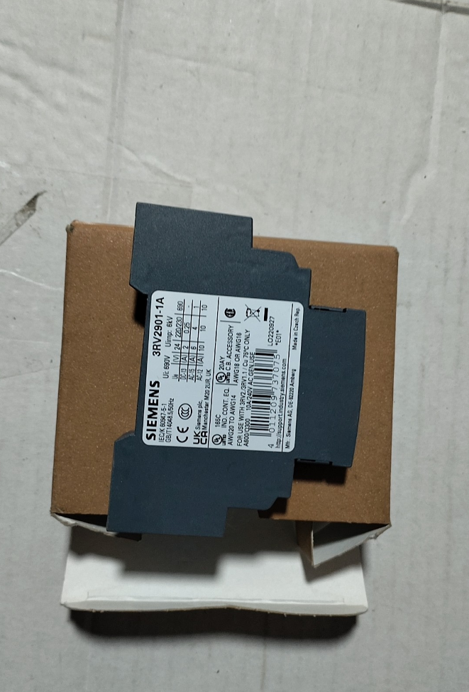

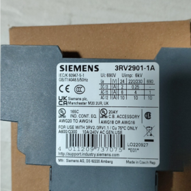
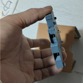
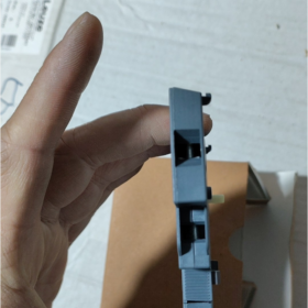

3RV2901-1A는 측면 장착형 수동형 제품입니다. 보조 접점 모듈 아래에 지멘스 시리우스 모듈형 시스템, 3RV2 시리즈 모터 보호 회로 차단기용 표준 확장 액세서리 역할. 내장된 조합을 갖추고 있습니다. 1 평상시 열림 (아니요) + 1 평상시 닫힘 (NC) 접점 및 나사 클램프 단자, 이 모듈은 회로 차단기 열림/닫힘 상태 피드백을 포함한 기능을 활성화합니다., 고장 트립 신호 출력, 제어회로의 전기적 연동, PLC를 통한 원격 신호 획득. 모터 시동 보호와 같은 산업용 전력 분배 시나리오에 널리 적용됩니다., 배전 캐비닛의 신호 표시, 및 안전 인터록 회로.
- 모델 코딩 분석
| 코드 세그먼트 | 설명 |
| 3RV2 | Siemens SIRIUS 시리즈 모터 보호 회로 차단기의 주요 제품 라인 코드, 그것이 속한 제품 시스템 식별 |
| 901 | 측면 장착 보조 접점용 제품군 코드, 전면 장착 접점과 같은 다른 회로 차단기 액세서리와 차별화, 결함 신호 접점 및 저전압 릴리스 |
| 1에이 | 사양 버전 식별자: “1” 1NO+1NC 접점 구성을 나타냅니다.; “에이” 나사 클램프 배선 단자를 나타냅니다. |
III. 핵심 기술 사양
| 매개변수 항목 | 사양 값 |
| 제품 유형 | 회로 차단기용 측면 장착 보조 접점 모듈 |
| 연락처 구성 | 1 평상시 열림 (아니요) + 1 평상시 닫힘 (NC), 패시브 건식 접점 |
| 호환 가능한 제품 | 3RV2 시리즈 모터 보호 회로 차단기 (모든 프레임 크기 S00 ~ S3) |
| 정격 절연 전압 Ui | 690 뷔와 |
| 정격 임펄스 내전압 Uimp | 6 kV |
| 기존 열 전류 즉 | 10 그리고 AC |
| 활용 카테고리 AC-15에 대한 정격 전류 | 6 에이 @ 24 뷔와; 4 에이 @ 230 뷔와; 3 에이 @ 400 뷔와; 1 에이 @ 690 뷔와 |
| 활용 카테고리 DC-13에 대한 정격 전류 | 2 에이 @ 24 DC에서; 0.5 에이 @ 110 DC에서; 0.25 에이 @ 250 DC에서 |
| 배선 방법 | 나사 클램프 단자 |
| 보호 등급 | IP20 (손가락 안전 보호) |
| 주변 작동 온도 | -20℃ ~ +60℃ |
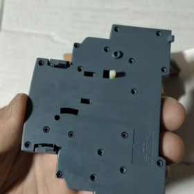
| 장착 방법 | 회로 차단기 측면에 스냅온 장착 |
| 단위당 순중량 | 0.045 kg |
| 규정 준수 인증 | IEC 60529; supports marine, 철도, KC and other industry certifications |
- Terminal Pin Definition
The module has 4 총 배선 단자. Contact numbers comply with the standard naming rules of Siemens industrial control components. Passive contacts have no distinction between input and output, and the definitions are as follows:
| 터미널 번호. | Contact Belonged To | 기능 설명 |
| 33 | 평상시 열림 (아니요) | First terminal of NO contact; conducts with terminal 34 when the circuit breaker is closed |
| 34 | 평상시 열림 (아니요) | Second terminal of NO contact; disconnects from terminal 33 when the circuit breaker is open |
| 41 | 평상시 닫힘 (NC) | First terminal of NC contact; conducts with terminal 42 when the circuit breaker is open |
| 42 | 평상시 닫힘 (NC) | Second terminal of NC contact; disconnects from terminal 41 when the circuit breaker is closed |
- Compatible Product Range
Full-series compatibility: 3RV2 series motor protection circuit breakers covering four standard frame sizes S00, S0, S2, S3
Corresponding circuit breaker model series: 3RV20 (S00 frame), 3RV21 (S0 프레임), 3RV23 (S2 frame), 3RV24 (S3 frame)
Maximum 2 modules can be installed laterally on one circuit breaker (1 왼쪽 조각과 1 오른쪽에), 최대 지원 2 확장 연락처 그룹
- 설치 및 작동 사양
- 하드웨어 설치 단계
- 차단기의 주회로 및 제어회로는 잔류전압 없이 완전히 전원이 차단되었는지 확인하십시오..
- 보조접점 모듈을 차단기 측면의 장착 가이드 홈에 맞춰 정렬하세요., 버클이 단단히 고정될 때까지 수직으로 밀어 넣습니다., 변속기 레버가 회로 차단기 메커니즘에 완전히 맞물렸는지 확인하세요..
- 제어케이블의 절연층을 5~7mm 벗겨냅니다., 번호별로 해당 터미널에 와이어를 연결, 나사의 권장 조임 토크는 0.8~1.2N·m입니다..
- 설치 후, 회로 차단기를 수동으로 열고 닫습니다., 멀티미터의 연속성 테스트 범위를 통해 접촉 동작 논리 및 연속성을 검증합니다..
- 조작상의 주의사항
모듈은 수동 건식 접점을 채택합니다.. 전원 회로를 직접 연결하지 마십시오.; 제어 및 신호 회로에만 적용 가능.
유도성 부하를 구동할 때 (접촉기 코일, 중간 릴레이), 서지 억제 부품을 연결하는 것이 좋습니다. (RC 회로 또는 다이오드) 동시에 역기전력을 억제하고 접점 서비스 수명을 연장합니다..
실제 부하 전류는 접촉 과열을 피하기 위해 해당 전압 레벨에서 정격 작동 전류를 초과해서는 안 됩니다., 절제 및 접착 실패.
Ⅶ. 일반적인 오류 문제 해결 매트릭스
| 결함 현상 | 근본 원인 분석 | 단계별 솔루션 |
| 접점에서 신호가 출력되지 않음; 회로 차단기 작동으로 상태가 전환되지 않습니다. | 1. 모듈이 완전히 끼워지지 않음, 차단기 메커니즘에서 분리된 변속기 레버 | 1. 전원 끄기, 모듈을 다시 삽입, 완전 버클 잠금 및 정상적인 변속기 스트로크 확인 |
| 2. 배선의 헐거움이나 단자의 산화로 인한 접촉불량 | 2. 배선 단자를 조이세요, 산화된 접점을 연마하고 케이블 연속성을 다시 테스트합니다. | |
| 3. 과부하로 인한 접촉절제 및 유착 | 3. 접점 모듈을 교체하고 부하 전력이 정격 값을 초과하는지 확인하십시오. | |
| 잘못된 신호 트리거링, 빈번한 상태 변동 | 1. 제어선의 전원 케이블로 인한 심각한 전자기 간섭 | 1. 제어 케이블과 전원 케이블의 분리 배선, 한쪽 끝에서만 실드를 안정적으로 접지합니다. |
| 2. 케이블 절연체 손상이나 단자간 먼지 쌓임으로 인한 누전 | 2. 손상된 케이블 교체, 단자 먼지 청소 및 절연저항 측정 | |
| 3. 캐비닛 진동으로 인한 접촉 불량 | 3. 회로 차단기와 모듈의 장착 패스너를 고정합니다.; 필요한 경우 충격 흡수 조치를 추가합니다. | |
| 회로 차단기가 닫힌 후 NC 접점이 열리지 않음 | 1. 변속기 레버의 작동 스트로크가 충분하지 않은 오프셋 모듈 장착 | 1. 완전한 기계적 결합을 보장하기 위해 모듈 장착 위치를 재보정하세요. |
| 2. 접점의 기계적 걸림 또는 내부 리셋 스프링 고장 | 2. 보조접점모듈 전체 교체; 사용자가 내부구조물을 분해 및 유지보수하는 것을 금지합니다. |
Ⅷ. 동일 시리즈의 보조 접점 모델 비교
| 모델 | 연락처 구성 | 배선 방법 | 핵심 차이점 |
| 3RV2901-1A | 1아니요 + 1NC | 나사 터미널 | 유니버셜 측면 장착형, 가장 널리 사용되는 표준 사양 |
| 3RV2901-2A | 2아니요 | 나사 터미널 | 듀얼 NO 접점으로 측면 장착, 다중 채널 신호 피드백 애플리케이션에 적합 |
| 3RV2901-3A | 2NC | 나사 터미널 | 듀얼 NC 접점을 갖춘 측면 장착, 안전 인터록 회로에 적합 |
| 3RV2901-1D | 1아니요 + 1NC | 스프링 터미널 | 측면 장착, 도구가 필요 없는 빠른 연결, 빈도가 높은 유지 관리 시나리오에 적합 |
3RV2901-1A의 작동 원리
3RV2901-1A는 순수 기계식 연결 수동 건식 접점 보조 접점 모듈입니다.. 핵심 작동 원리는 3RV2 회로 차단기 본체의 작동 메커니즘과 견고한 기계적 결합에 의존합니다., 차단기 주접점의 물리적 개폐위치를 전기접점의 ON/OFF 신호로 변환. 작동 전반에 걸쳐 추가 작동 전원 공급 장치가 필요하지 않습니다., 수동적인 상태 피드백 구성 요소로 만들기.
- 기계적 연결 전달 원리
모듈의 핵심 구동 메커니즘입니다., 전자 부품을 사용하지 않고 회로 차단기의 기계적 움직임에 의해 완전히 구동됩니다.:
- 리지드 커플링 구조: 모듈을 차단기 측에 스냅 장착한 후, 내부 변속기 구동 레버는 차단기 작동 스핀들의 연결 슬롯에 정밀하게 내장되어 있습니다., 회로 차단기의 주 접촉 메커니즘과 동기식 강체 연결을 형성합니다., 지연 및 편차 없는 작업 제공.
- 행동의 원동력: 차단기가 닫혔을 때, 실수로 열리거나 넘어졌습니다., 주 접점 회전축의 각도 변위가 모듈의 전달 레버를 직접 밀고 내부 이동 접점 브래킷을 구동하여 변위시킵니다., 접점 상태 전환 실현. 열린 상태에서, 모듈 내부에 내장된 리셋 스프링이 초기 접점 상태를 유지.
- 패시브 기능의 본질: 모듈 자체에는 전원 공급 회로나 신호 처리 회로가 없습니다.. 접점은 기계적 힘에 의해서만 구동됩니다., 따라서 강력한 전자기 간섭 방지 성능과 높은 신뢰성을 자랑합니다., 전자파 방해가 심한 산업 환경에서도 안정적으로 작동할 수 있습니다..
- 접점의 전기적 작동 논리
모듈에는 한 세트의 수동 건식 접점이 장착되어 있습니다. (1아니요 + 1NC). 접점 상태는 회로 차단기 주 접점의 위치와 엄격하게 일치합니다., 개봉의 유발 원인과 관련 없음 (수동 열기 / 과부하 여행 / 단락 여행). 구체적인 상태 대응은 다음과 같습니다:
| 회로 차단기 상태 | 상시 개방 접점 (아니요, 터미널 33-34) | 상시 폐쇄 접점 (NC, 터미널 41-42) |
| 열린 상태 (초기 정상 상태, 수동 개방 또는 오류 트립 이후 포함) | 열려 있는 | 닫은 |
| 닫힌 상태 (정상 마감, 유지된 참여) | 닫은 | 열려 있는 |
주요 전기적 특징 설명
접점은 내장된 전원이 없는 수동 건식 접점입니다.. 사용 중, 제어 전원 공급 장치와 부하는 외부 회로에 직렬로 연결되어야 합니다., 다양한 AC 및 DC 제어 회로와 호환 가능.
접점의 차단 용량은 제어 수준 부하에만 적용됩니다. (활용 카테고리 AC-15/DC-13). 주전원 회로에 직접 연결하는 것은 금지되어 있습니다.; 그렇지 않으면, 아크 소화 능력이 부족하면 접촉 제거 및 접착 실패로 이어질 수 있습니다..
III. 대표적인 기능의 구현원리
- 회로 차단기 상태의 원격 피드백
PLC 입력점과 상태 표시 램프를 NO 접점 회로에 직렬로 연결합니다.: when the circuit breaker is closed, NO 접점이 닫히고 회로가 작동합니다., PLC는 레벨 신호를 수집하고 표시 램프가 켜져 작동 상태를 직관적으로 피드백합니다. “회로 차단기가 닫혔습니다.”; 차단기가 열리거나 실수로 트립된 경우, NO 접점이 열리고 신호가 사라집니다., 상위 컴퓨터 종료 경보를 유발할 수 있습니다..
- 전기 안전 인터록
NC 접점을 인접한 회로의 폐쇄 제어 회로에 직렬로 연결하여 두 모터 또는 두 전원 공급 장치 간의 하드 전기 인터록을 실현합니다.: 이 회로 차단기가 닫힐 때, NC 접점이 열리고 다른 회로의 폐쇄 제어 경로가 강제로 차단됩니다., 두 회로의 동시 폐쇄로 인한 단락 및 기계적 간섭과 같은 오류 방지, 소프트웨어 로직 인터록보다 훨씬 높은 신뢰성.
- 오류 발생 시 연결된 종료
과부하 또는 단락 사고로 인해 차단기가 트립된 경우, 주 접점은 분리되고 보조 접점은 동기적으로 재설정됩니다.. NO 접점이 열려 접촉기와 인버터의 활성화 회로를 직접 차단합니다., 추가 감지 구성 요소 없이 오류 상황에서 신속한 종료 보호 실현.
- 오류 신호 접점과의 핵심 원리 차이점
일반 위치 보조 접점과 오류 신호 접점은 쉽게 혼동됩니다., 작동 메커니즘에는 본질적인 차이가 있습니다.:
이 제품 (3RV2901-1A, 보조 접점 위치): 주요 접점의 물리적 위치에 따라서만 동작합니다.. 수동개방과 고장트립을 구별할 수 없습니다.. 주요 연락처가 분리되면, 접점이 초기 상태로 돌아갑니다.
결함 신호 접점 (예를 들어. 3RV2901-2E): 내부 트립 메모리 메커니즘 탑재. 과부하 또는 단락 오류로 인해 회로 차단기가 작동하는 경우에만 작동합니다., 일반적인 수동 열기로는 트리거되지 않습니다., 오류 경보 식별에 특별히 사용됩니다..


 Impulse Heat-Sealing Temperature Controller")


")


NH42-63-318x560.png "CHINT PC형 자동절환스위치 (ATS)NH42-63/4SZ")


