 접촉기,회로 차단기,감지기,인코더,PLC,변환기

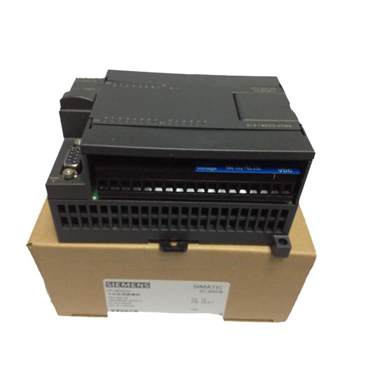


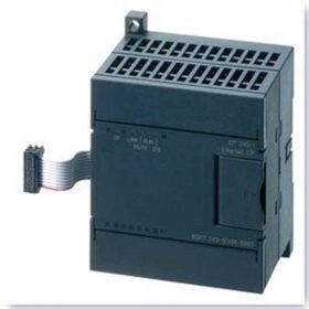
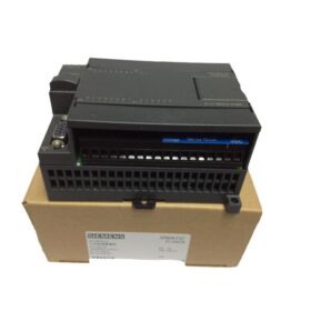
그만큼 Siemens 6ES72350KD220XA0 is an analog input/output module specifically designed for the S7200 series PLC, suitable for scenarios in industrial automation systems that require highprecision analog signal acquisition and control. The following is a detailed analysis from aspects such as technical parameters, 기능적 특성, 애플리케이션 시나리오, 및 구매 제안:
- 핵심 기술 매개변수
- 신호 유형Siemens 6ES72315QA300XB0 module
Input Channel: 4 아날로그 입력 (일체 포함) 채널, supporting ±10V DC voltage signals, with a resolution of 12 bits and an accuracy of ±0.5% FS (풀 스케일).
출력 채널: 1 아날로그 출력 (에) 채널, supporting ±10V DC voltage signals, with a resolution of 12 비트.
- 전원 공급 장치 요구 사항6ES71425AF000BA0 Siemens
24V DC 전원 공급 장치 (the module’s own power consumption is approximately 30mA).
- 통신 인터페이스Siemens 1FL60342AF211LH1 Servo Motor
Directly connected to the CPU module through the bus interface (flat cable) of the S7200 PLC, without the need for additional communication protocol configuration.
- 물리적 특성Siemens converter 6SE64402UD420GA1
치수: 14.4×22.0×12.3cm, with a weight of approximately 0.33kg, suitable for compact installation environments.
- 인증 및 규정 준수Siemens V20 Inverter 15KW of Model 6SL32105BE315UV0
Complies with CE certification, and some suppliers mention 3C certification (특정 모델을 확인해야 합니다.).
- Functional Characteristics and Application Scenarios
- 기능적 특성친트 변환기 (NVF2G18.5/TS4 or NVF2G18.5/PS4
Highprecision Conversion: A 12bit resolution ensures accurate acquisition and output of analog signals, suitable for monitoring and control of continuous variables such as temperature, 압력, 그리고 흐름.
유연한 구성AB Inverter 25BD043N114
The input channels can select the range (such as ±5V, ±10V) through DIP switches.
The output channels support directly driving actuators (such as regulating valves, 주파수 변환기) with voltage signals.
Antiinterference Design: Builtin filter circuit to reduce electromagnetic interference (EMI) in industrial environments.
고장 진단: Quickly locate module anomalies through LED indicators (such as the SF fault light).
- 일반적인 애플리케이션 시나리오
산업 자동화
Closedloop temperature control of production lines (such as injection molding machines, 원자로).
Pressure monitoring and regulation of hydraulic systems.
프로세스 제어
Liquid level and pH value monitoring and control of pumps and valves in water treatment plants.
Collection of electrical parameters (전압과 같은, 현재의) in energy management systems.
Experimental Equipment
Laboratory data collection (such as sensor signal recording).
III. Installation and Configuration Guide
- Hardware Installation
모듈 연결
Directly insert the EM235 module into the expansion slot of the S7200 PLC, and connect it to the CPU module through a flat cable (such as CPU224, CPU226).
Ensure that the wiring is firm to avoid signal interference or module damage caused by looseness.
Signal Wiring
아날로그 입력
전압 신호: Connect the sensor output (such as ±10V) to the AI channel, and ground the shielding wire at one end.
현재 신호: An external 250Ω resistor is required (such as converting 420mA to 15V).
아날로그 출력
Directly connect to the actuator (such as the AI terminal of the frequency converter), and avoid longdistance wiring.
전원 공급 장치 연결
The 24V DC power supply needs to be independently powered, and avoid sharing the ground with the power supply for power devices.
- 소프트웨어 구성 (Taking STEP 7Micro/WIN as an Example)
- Channel Definition
Configure the type (voltage/current) and range of the analog channels in the PLC programming software.
예: Set AIW0 as a ±10V input and AQW0 as a ±10V output.
- Data Processing
Convert the analog value (such as AIW0) to engineering quantities (such as temperature, 압력) through the MOV instruction.
예:
- Output Control
Send the analog value to the actuator through AQW0.
- 구매 및 대체 솔루션
- Market Status
공급 상황: 이 모델은 단종되었습니다 (discontinued in October 2017), and is currently supplied as spare parts with limited inventory.
가격대
Brand new original: Consult wa: 8613811255435 (there are large differences among different channels).
- 대체 모델
직접 교체
6ES72350KD220XA8 (CN version): It has exactly the same functions as the original model, supports the Chinese programming environment, and can be directly replaced.
업그레이드된 교체
Analog modules of the S71200 series (such as SM 1234)
Supports more channels (such as 8AI/2AO), 더 높은 해상도 (16 비트), and is compatible with the TIA Portal programming environment.
Requires replacing the CPU and programming software, suitable for new projects or system upgrades.
- 결함 문제 해결 및 유지 관리
- 일반적인 결함 및 해결 방법
No Signal Input
Check the power supply of the sensor, 배선, and range settings.
Test whether there is voltage in the AI channel (measure between AIx and AGND with a multimeter).
Abnormal Output
Confirm whether the power supply and wiring of the actuator are correct.
Check whether the output value of AQW0 is within a reasonable range (~와 같은 032000 corresponding to ±10V).
- Longterm Maintenance
Regularly clean the dust on the surface of the module to ensure good heat dissipation.
Check whether the wiring terminals are loose to avoid poor contact.
If using a secondhand module, it is recommended to conduct functional tests (such as calibrating input and output).
The installation of the Siemens 6ES72350KD220XA0 module (EM235) needs to combine hardware connection and software configuration. The following are detailed steps and precautions:
- Hardware Installation: Physical Connection and Wiring Specifications
- Module Fixing and Expansion Connection
설치 환경 요구 사항
Install vertically in the control cabinet and avoid horizontal placement, which may affect heat dissipation.
Reserve at least 50mm of heat dissipation space and keep away from strong interference sources such as frequency converters and transformers.
DIN Rail Installation Steps (참조)
- CPU Installation
Open the DIN clamp at the bottom of the CPU, snap it onto the rail, and push the clamp back to lock it.
- Expansion Module Installation
Remove the bus connector cover on the right side of the CPU (gently pry it with a screwdriver).
Pull out the clamp at the bottom of the EM235 module, hang it on the rail, and slide it to the left until the bus connector is fully engaged with the CPU.
Push the clamp back, 그리고 “딸깍 하는 소리” sound indicates that the installation is in place.
Panel Installation
Fix it through the installation holes at the top and bottom of the module using M4 screws, and ensure that the screw torque is moderate (approximately 0.5N·m).
- 주회로 배선
전원 공급 장치 연결
24V DC Input: Connect the positive pole (L+) of the external 24V power supply to the `L+` terminal of the module, and connect the negative pole (중) to the `M` terminal.
메모: The power supply needs to be independently powered, and avoid sharing the ground with the power supply for power devices.
아날로그 입력 (일체 포함) 배선 (참조)
전압 신호 (±10V)
Twowire system: The sensor needs an external 24V power supply, connect the positive pole of the signal to `AIx+`, and the negative pole to `AIx`.
현재 신호 (420엄마)
- Antiinterference Measures
Shielding and Grounding (참조)
Use a doubletwisted shielded wire for the signal cable, and ground the shielding layer at one end through the grounding terminal (체육) on the module side.
Establish an equipotential body: Connect the metal frame of the control cabinet, the PE terminal of the module, and the grounding end of the sensor through a copper busbar, and the grounding resistance < 10오.
배선사양
Lay the analog signal wires separately from the power wires (with a spacing > 30cm), and avoid parallel routing.
For longdistance signals (>50중), a signal isolator needs to be installed.
- 소프트웨어 구성: Parameter Setting and Programming Implementation
- Hardware Configuration and Parameter Initialization
DIP 스위치 설정 (참조)
Configure the input range (such as setting SW1SW3 to `ON` to select ±10V) through the 8bit DIP switch on the side of the module.
If the module is installed in the first expansion slot on the right side of the CPU, the address remains the default; if it is installed in other positions, it needs to be manually allocated in the programming software.
- Programming Implementation (Taking STEP 7Micro/WIN as an Example)
Reading Analog Input
Writing Analog Output
Analog Filtering
Enable the filtering function in the “System Block”, and set the number of samples (~와 같은 8 타임스) and the dead zone (such as ±5%).
- Function Testing and Calibration
Noload Test
부하를 분리하세요, force the output of a fixed value through the programming software (such as AQW0 = 16000 corresponding to 5V), and measure whether the output terminal is normal with a multimeter.
부하 테스트
Connect the actuator, gradually adjust the output value, and observe whether the device runs smoothly.
구경 측정
If high precision is required, a highprecision signal source needs to be used for calibration (such as when the input is 5V, the module should output 16000).
III. Precautions and Common Problem Troubleshooting
- 안전한 작동
Poweroff Operation: Before installing or removing the module, cut off the power supply of the PLC and all related devices, 그리고 기다려 5 분 (to ensure that the capacitor is discharged).
배선검사
전원 전압을 확인하세요., signal polarity, and whether the wiring is loose with a multimeter before powering on.
- 결함 문제 해결
| 현상 | 가능한 이유 | 솔루션 |
| The SF light of the module is on | 배선 오류, signal overrange, or module failure | 배선을 확인하세요, reset the DIP switch, and replace the module |
| 비정상적인 출력 (such as jumping) | Interference, 접지 불량, or programming error | Optimize the wiring, check the grounding, and debug the program |
| No response to input | Sensor failure, incorrect range setting, or channel not enabled | Test the sensor, confirm the DIP switch, and check the program logic |
- Alternative Solutions and Upgrade Suggestions
직접 교체
6ES72350KD220XA8 (CN version): It has the same functions as the original model, supports the Chinese programming environment, and can be directly replaced.
업그레이드된 교체
에스엠 1234 module of the S71200 series: Supports more channels (such as 8AI/2AO), 더 높은 해상도 (16 비트), and is compatible with TIA Portal programming, but requires replacing the CPU and software.
The installation of the EM235 module needs to strictly follow the principles of “reliable hardware connection, accurate software configuration, and optimized antiinterference in the environment”. Through reasonable grounding, 배선, and parameter setting, highprecision transmission of analog signals can be ensured. For systems in longterm operation, it is recommended to regularly check the wiring terminals and the status of the module, and perform functional calibration when necessary to maintain the stability of the equipment. If higher performance or extended functions are required, it is preferred to upgrade to the S71200/1500 series.
The Siemens 6ES72350KD220XA0 is a classic analog module. Although it has been discontinued, due to its high costeffectiveness and stability, it is still widely used in the field of industrial automation. 새로운 프로젝트의 경우, it is recommended to give priority to upgrading to the S71200 series; for the maintenance of existing systems, attention should be paid to the supply situation of spare parts and compatibility. 구매시, be sure to choose a reliable channel and reserve enough testing time to ensure the normal operation of the module.





NH42-63-318x560.png "CHINT PC형 자동절환스위치 (ATS)NH42-63/4SZ")



