 Contactor,circuit breaker,sensor,Encoder,PLC,Converter

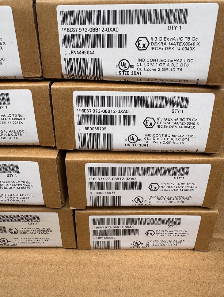

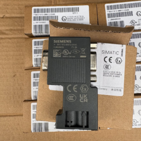
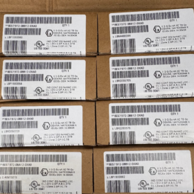
Full Model & Official Description
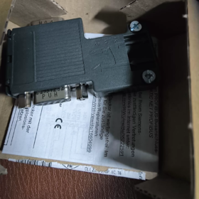
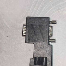
Order No.: 6ES7 972-0BB12-0XA0
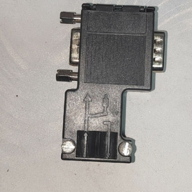
SIMATIC DP, PROFIBUS Bus Connector, up to 12 Mbit/s; 90° vertical cable outlet, with PG programming socket, integrated switchable isolated termination resistor, screw terminal wiring.
- Model Code Breakdown
| Code Segment | Definition |
| 6ES7 | SIMATIC S7 automation system accessories |
| 972 | PROFIBUS RS485 bus connector series |
| 0BB | 90° outlet + with PG programming socket; 0BA = without PG socket |
| 12 | Screw terminal (non-FastConnect stripping structure) |
| 0XA0 | Standard general version (Made in Germany) |
- Core Electrical & Mechanical Specifications
- Communication Standard: PROFIBUS-DP / MPI (RS485)
- Max Baud Rate: 12 Mbit/s
- Termination Resistor: Built-in 220Ω, ON/OFF toggle switch (with isolation)
Termination switch set to ON for the first and last station on the bus; OFF for all intermediate stations
- Wiring Method: Screw terminals, conventional cable stripping, FastConnect cable is NOT supported
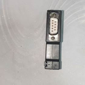
- Interfaces: Rear 9-pin Sub-D male connector; independent front 9-pin PG female socket (online debugging without bus interruption)
- Cable Outlet: 90° vertical downward outlet, suitable for compact cabinet installation
- Overall Dimensions: 15.8 mm(W) × 64 mm(H) × 35.6 mm(D)
- Protection Class: IP20 (indoor cabinet installation only)
- Temperature Range: Operating: 0 ℃ ~ +60 ℃; Storage: -40 ℃ ~ +70 ℃
- Net Weight: Approx. 60 g
- Wiring Definition (Standard PROFIBUS Purple Cable)
Terminal A: Green signal wire
Terminal B: Red signal wire
> ⚠️ Reversing A/B will directly trigger communication failure; secure the cable shield to the connector metal clamp with grounding at both cable ends.
- Cross Comparison of Similar Models (Selection Reference)
| Order Number | Outlet Angle | PG Socket | Wiring Type |
| 6ES7972-0BB12-0XA0 | 90° | ✅ Yes | Screw terminal (this model) |
| 6ES7972-0BA12-0XA0 | 90° | ❌ No | Screw terminal |
| 6ES7972-0BB42-0XA0 | 35° angled outlet | ✅ Yes | Screw terminal |
| 6ES7972-0BB52-0XA0 | 35° angled outlet | ✅ Yes | FastConnect quick stripping |
- Applicable Devices & Scenarios
S7-300 / S7-400 CPU DP ports
ET200M, ET200S DP interface modules
PROFIBUS-DP inverters, servo drives, instruments, encoders
S7-200 SMART RS485 (MPI/DP mode)
- Key Application Notes & Common Pitfalls
- FastConnect quick stripping technology is not supported. FC cables cannot be directly crimped; select 0BB52 / 0BA52 series if FC cables are used.
- Online monitoring via PG socket does not require bus disconnection, ideal for non-stop equipment debugging.
- Only enable termination resistors at the two ends of one PROFIBUS bus. Multiple active termination resistors cause unstable communication and packet loss.
- Avoid excessive tension on terminals during cable bending. Reliably crimp the shield; dual-end grounding is strongly recommended for long-distance communication.
- Wide-Temperature Special Version (For Harsh Environments)
6AG1972-0BB12-2XA0 (SIPLUS Version)
Derived from 6ES7972-0BB12-0XA0 with anti-corrosion coating. Operating temperature: -25℃ ~ +70℃, applicable to outdoor, HVAC, metallurgy and high-humidity environments.
- Replacement Information
Direct form-fit replacement: Prioritize identical part number for no hardware modification.
If 35° angled outlet is required: Replace with 6ES7972-0BB42-0XA0.
For new projects, prefer FastConnect version 6ES7972-0BB52-0XA0 for higher wiring efficiency.
Supplementary Document: PROFIBUS DP Topology, Wiring Specification & Troubleshooting Matrix
Compatible with 6ES7972-0BB12-0XA0 Bus Connector
- Standard PROFIBUS Bus Topology (Linear Topology; Star/Tree Topology Forbidden)
Mandatory Topology Rules
- Linear daisy-chain connection only; T-branches and star wiring are strictly prohibited. Branches cause signal reflection, communication jitter and packet loss.
- Set termination resistor to ON only on the first and last connectors of the whole bus; all intermediate stations must be set to OFF.
- Maximum two cables (IN / OUT) per bus connector. Do not terminate multiple wires on one screw terminal.
- Detailed Wiring Specification for 6ES7972-0BB12-0XA0
2.1 Terminal Definition
A: Green wire
B: Red wire
> ⚠️ Red = B, Green = A. A and B must not be swapped.
2.2 Shield Handling
- Unfold the metal shielding braid of PROFIBUS purple cable; do not cut off the copper mesh.
- Lay shielding braid flat and clamp under the metal shield clip of the connector.
- Cabinet layout recommendation: Reliably ground the shield at both ends of the bus. Dual-end grounding is preferred for long-distance and high-interference sites; single-end grounding is adopted if potential difference exists between ground points.
- Never short shielding braid with signal wires A/B!
2.3 Termination Resistor Switch Operation
ON: 220Ω termination resistor activated (for first & last station)
OFF: Termination resistor disconnected (all intermediate stations)
> Typical Fault: Multiple stations with termination resistor ON → Impedance mismatch, frequent communication errors.
2.4 PG Programming Socket Instructions
This model integrates a 9-pin female PG socket:
Programming cable can be plugged for online monitoring without cutting off the bus.
⚠️ PG socket is only for temporary debugging; do not permanently connect other slave devices.
- Step-by-Step Wiring Procedure
- Unscrew and open the connector housing;
- Strip outer cable sheath, remove 6~7mm insulation of red/green cores;
- Route red wire to terminal B, green wire to terminal A. Tighten screws with torque 0.4~0.6Nm (avoid thread slipping);
- Clamp shielding braid into metal shield clip;
- Verify no short circuit between A and B, no exposed conductors touching each other;
- Toggle termination resistor switch according to station position;
- Close housing, insert connector into module Sub-D port and lock fixing screws.
- PROFIBUS DP Communication Troubleshooting Matrix
| Fault Symptom | Root Cause | Stepwise Remedial Actions |
| All stations offline; master reports DP fault (BF LED steady red) | 1. Termination resistors disabled at both ends | 1. Check two end connectors, set termination switch to ON |
| 2. A/B reversed for the whole bus | 2. Verify A(green)/B(red) wiring section by section | |
| 3. A/B short-circuit somewhere on bus | 3. Power off, use multimeter to check A-B short circuit | |
| 4. Broken bus cable | 4. Isolate cable segments to locate break point | |
| Random drop-out of partial slaves, flashing BF LED, intermittent communication | 1. Termination resistor mistakenly enabled on intermediate stations | 1. Inspect termination switch on every connector |
| 2. Poor shield grounding & electromagnetic interference | 2. Re-tighten shield crimp and grounding bar | |
| 3. Cracked/bent cable insulation | 3. Rewire to eliminate all branch lines | |
| 4. Branched (star) bus wiring | 4. Cross-check baud rate vs maximum cable length table | |
| 5. Baud rate too high, bus length exceeds limit | ||
| Devices near master run normally, remote slaves drop out frequently | 1. Bus length exceeds limit corresponding to selected baud rate | 1. Reduce communication baud rate |
| 2. Ground loop interference caused by multi-point grounding | 2. Optimize shield grounding scheme | |
| 3. Low-quality non-standard PROFIBUS Type A cable | 3. Replace with certified PROFIBUS Type A cable | |
| Communication fails after PG cable insertion; restored after unplugging | PG cable contains built-in termination resistor, conflicting resistance at bus terminal | Avoid long-term PG connection on end-node connectors; use PG socket on intermediate stations for debugging |
| Communication works after commissioning, failure occurs after equipment vibration | Loose screw terminals, poor wire contact; cable tension pulling connector | Retighten terminal screws; fix cables with cable ties to avoid mechanical load on connectors |
- Baud Rate — Maximum Cable Length Table (PROFIBUS Type A Cable)
| Baud Rate | Max Bus Length |
| 9.6 kbit/s | 1200 m |
| 19.2 kbit/s | 1000 m |
| 187.5 kbit/s | 400 m |
| 500 kbit/s | 200 m |
| 1.5 Mbit/s | 100 m |
| 3 ~ 12 Mbit/s | 100 m |
- Strict Forbidden Operations (Red Line Rules)
- ❌ Do not terminate more than two signal wires under one screw terminal
- ❌ Do not construct PROFIBUS bus with star topology or T-branches
- ❌ Do not activate termination resistor on multiple stations simultaneously
- ❌ Do not swap signal wire A and B
- ❌ Do not short shielding braid with A/B conductors
- ❌ Do not replace standard PROFIBUS Type A cable with ordinary 2-core cable
- ❌ Do not sharply bend cable near the connector outlet to prevent internal wire fracture
- Additional Selection Reminder
6ES7972-0BB12-0XA0 adopts screw terminal wiring and does NOT support FastConnect cables.
For new mass rollout projects, it is recommended to select:
6ES7972-0BB52-0XA0 (35° outlet + PG socket + FastConnect)





NH42-63-318x560.png "CHINT PC-type automatic transfer switches (ATS)NH42-63/4SZ")



