 Contactor,circuit breaker,sensor,Encoder,PLC,Converter

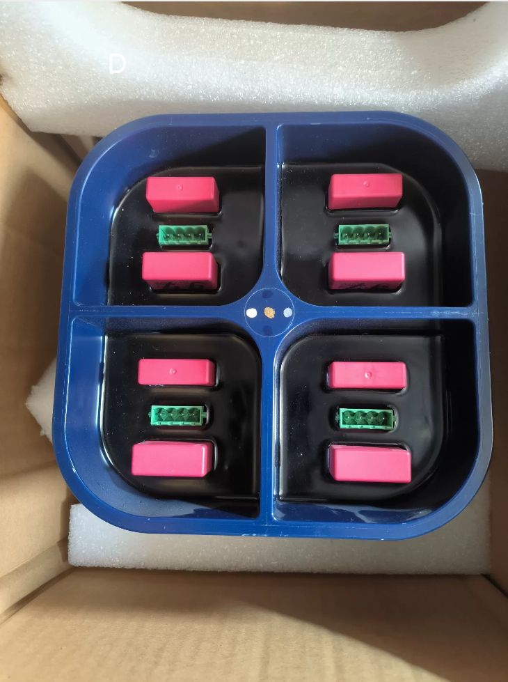

Full Model Designation: IPS 21-35 AD, Material Code 3BHB017688R0001
- Basic Information
Manufacturer: ABB (originally Sécheron, Switzerland)
Category: Isolated Gate Drive Power Module / IGCT Drive Power Supply Unit (IPS – Isolated Power Supply)
Applicable Systems: ABB medium-voltage frequency converters and IGCT converters (ACS5000, ACS6000, PCS6000 series high-power variable speed drives)
Origin: Germany / Switzerland
Material Coding Rule: Serial code starting with 3BHBxxxxR0001 = ABB drive power spare part series
- Core Function
Supplies galvanically isolated regulated DC power to IGCT gate drive units; achieves separation between power circuit and control circuit. Equipped with overcurrent, short-circuit and undervoltage protection. Standard component installed inside power units of high-power medium-voltage converters.
Common Misconception: It is not an excitation board, PLC I/O module or IGCT semiconductor device; it is a dedicated power supply unit for gate drives.
- Key Electrical Specifications
| Item | Parameter |
| Input Power | 110–250 VAC, 50/60 Hz (single-phase AC) |
| Isolated Output | 4 mutually isolated DC outputs (power supply for 4 sets of IGCT gate drive boards) |
| Protection Class | IP20 (for cabinet internal mounting) |
| Operating Temperature | -10 ℃ ~ +60 ℃ |
| Storage Temperature | -40 ℃ ~ +85 ℃ |
| Cooling Method | Natural air cooling, bottom-mounted heat sink |
| Construction | Sealed blue plastic housing, internally potted for moisture resistance and anti-vibration performance |
- Typical Application Equipment
- ABB ACS6000 medium-voltage converters (3kV / 6kV high-power drives)
- ABB ACS5000 medium-voltage converters
- Metallurgical rolling mills, mine hoists, large fans & pumps and other high-power drive systems
- High-power IGCT converters for rail transit and energy storage systems
- Spare Part & Replacement Guidelines
- Direct Replacement Model: Only 3BHB017688R0001 (IPS21-35AD) can be used for direct replacement. Other suffix variants within IPS21 series are not interchangeable due to different definitions of isolated output channels.
- Procurement Classification: Brand new original units / second-hand dismantled units. Many suppliers mislabel this product as excitation board or communication module; always verify the marking IPS21-35AD on the housing before order placement.
- Typical Fault Symptoms:
Power unit reports gate drive power fault or fiber communication interruption
Drive board LED indicators remain off after power-up; IGCT fails to trigger
Internal fuse blown, abnormal overheating of module housing
- Model Code Decoding
3BHB: Prefix for ABB drive power spare parts (IGCT-related assemblies)
017688: Internal component serial number
R0001: Revision version code
IPS21-35AD: Short product name (Isolated Power Supply Series 21)
In-depth Introduction to Overcurrent Protection Mechanism of ABB 3BHB017688R0001 (IPS21-35AD)
Module Positioning: Four-channel isolated power supply for IGCT gate drives inside ACS6000/ACS5000/PCS6000 medium-voltage converters. Designed by original Sécheron; sealed and potted with four independent isolated outputs to feed four IGCT gate drive boards.
Critical Note: Four output channels operate independently. Each channel is equipped with dedicated sampling and independent overcurrent protection circuits; the module does not implement unified current limiting for all channels.
- Overview of Three-Tier Protection Architecture
- Primary Stage: Cycle-by-Cycle (CBC) hardware current limiting for primary-side MOSFETs
- Secondary Stage: Independent sampling on four output channels, active constant-current limiting (overload protection)
- Final Protection: Output short-circuit triggers Hiccup Mode; prolonged faults activate thermal shutdown latch
Important Distinction
Overload (Mild Overcurrent): Constant-current limiting maintained, output voltage drops naturally without channel shutdown
Output Short-Circuit (Severe Overcurrent): Enables intermittent hiccup operation to avoid continuous high current damaging drive boards and the power module
All protection functions are implemented by analog hardware circuits without MCU participation. Protection logic is unaffected by communication or control circuit faults, complying with safety requirements for industrial drives.
- Hardware Detection Principle
2.1 Current Sampling Method
A high-precision power shunt resistor is connected in series to the negative rail of each isolated output channel.
Voltage difference across the shunt resistor is conditioned by operational amplifiers and fed into voltage comparators for comparison against internal precision reference voltage to judge overcurrent conditions in real time.
Advantage: Microsecond-level response with minimum filtering delay, capable of capturing inrush current during IGCT drive power-on.
2.2 Two-Tier Current Thresholds Defined by OEM Design
1) Overload Threshold (Current Limit Point I_LIM)
Triggered by gradual load rise, partial leakage current or increased power consumption caused by aging drive boards.
Action Mode: Active Constant-Current Limiting.
The power supply dynamically increases equivalent output impedance and clamps output current at the preset maximum value; output voltage declines naturally as load rises. The channel remains active as long as the fault does not deteriorate.
2) Short-Circuit Threshold (Short-Circuit Trip Point I_SC, higher than overload limit)
Triggered by direct short-circuit between output terminals, internal breakdown of drive board or fiber interface short-circuit.
Action Mode: Immediately block output of the corresponding channel, wait for fixed delay then attempt restart → Hiccup Protection.
- Complete Action Sequence under Two Fault Scenarios
Scenario 1: Single Channel Output Overload (Overload Overcurrent)
- Load current exceeds overload threshold; sampled voltage surpasses reference level
- Secondary feedback loop adjusts PWM duty cycle to implement constant current clamping
- Module maintains current-limiting operation without shutting down the channel
- Field Symptoms: Low supply voltage for drive boards, dim LED indicators on drive boards; frequency converter alarms Drive Undervoltage / Power Unit Fault
- Fault Recovery: When load current falls back within rated range after overload removal, output voltage restores automatically without module power cycle
Common Field Phenomenon: Long-term current-limiting operation caused by leakage of a single IGCT drive board, accompanied by slow temperature rise of module housing.
Scenario 2: Single Channel Output Short-Circuit (Severe Overcurrent / Short Circuit)
- Instantaneous current surge exceeds short-circuit threshold
- Comparator generates protection signal, transmitted via optocoupler isolation to primary-side PWM controller; PWM drive of this channel is immediately disabled
- Output remains blocked for fixed dormant period (typically tens of milliseconds)
- After dormant period expires, automatic restart attempt is initiated
- If short-circuit persists, protection shutdown repeats; cyclic intermittent operation forms periodic hiccup output
- Visual Feature: LED indicator of corresponding drive board flashes periodically
- Backup Thermal Interlock: Continuous long-term hiccup operation causes excessive heating of internal power devices, triggering overtemperature protection and full latch-off. Power supply must be cycled to reset.
- Key Characteristics (Critical for On-site Engineering)
- Independent protection for four channels
If one channel suffers short-circuit or overload, only the faulty channel is blocked; the other three channels keep normal power supply.
Extreme Risk Reminder: When one IGCT drive board inside power unit fails short, the other three IGCT drives remain energized. Complete power cut and full discharge are mandatory before maintenance; never assume all channels are de-energized due to single-channel fault.
- No channel interlock logic
Single-channel fault will not cut off the whole module’s AC input; only the faulty output branch is isolated.
- Automatic recovery logic
Overload fault cleared: Instant automatic recovery
Short-circuit fault cleared: Output resumes at next restart cycle without module power cycle
Only thermal latch triggered by sustained short-circuit requires AC power interruption for reset.
- Primary-side cycle-by-cycle peak current limiting (ultimate backup protection)
If multiple channels short simultaneously and secondary protection cannot suppress instantaneous surge current, CBC limiting on primary switch circuits restricts transformer primary peak current and prevents catastrophic failure of power switches, acting as the last safety barrier.
- Fault Linkage Between Overcurrent Protection and ACS6000/ACS5000 Converter System
- IPS channel current limiting → reduced supply voltage for gate drive board → insufficient IGCT gate drive amplitude
- Abnormal fiber transceiver status on drive board → power unit control board detects loss of fiber signal
- Main converter controller generates fault alarm: Power Unit Fault / Drive Power Fault / Fiber Communication Fault
- Important Note: The IPS module does not provide external hard-wired fault contact signals. The converter judges power supply abnormality indirectly via fiber communication status of gate drives.
- Typical Misjudgments & On-site Guidelines
- ❌ Misunderstanding: Single-channel overcurrent protection will shut down the entire IPS module
✅ Fact: Four channels work independently; only faulty channel enters intermittent operation.
- ❌ Misunderstanding: Hiccup mode equals permanent module damage
✅ Fact: Hiccup mode is normal protection response. Prioritize troubleshooting short-circuit of downstream IGCT drive boards or wiring; in most cases the IPS resumes normal operation after replacing defective drive board.
- ❌ Misunderstanding: Shunt resistor can be shorted to disable overcurrent protection
✅ Strictly Forbidden: After disabling current limiting, breakdown of drive boards will lead to irreversible burnout of internal high-frequency transformer and switching devices inside IPS.
- Environmental Influence: The potted structure has limited heat dissipation; protection threshold drifts slightly under high ambient temperature, which easily causes spurious current limiting during summer operation.
- Offline Test Procedure for Overcurrent Protection Verification
- Apply 110~230VAC input voltage to the module
- Connect adjustable electronic load to any output channel, gradually increase load current; confirm constant-current mode activates once rated upper limit is reached
- Short-circuit output terminals directly, verify periodic flashing of drive LED indicator (typical hiccup signature)
- Remove short-circuit condition; normal output resumes. This confirms full integrity of overcurrent protection circuit.





NH42-63-318x560.png "CHINT PC-type automatic transfer switches (ATS)NH42-63/4SZ")



