 Contactor,circuit breaker,sensor,Encoder,PLC,Converter

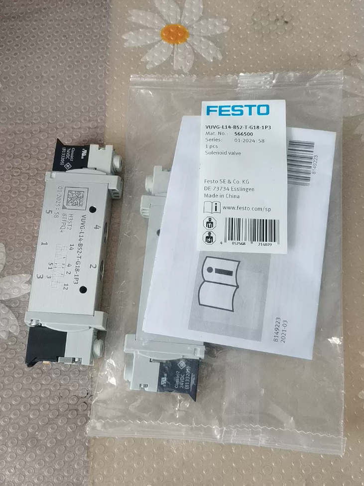

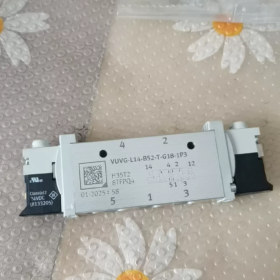
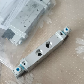
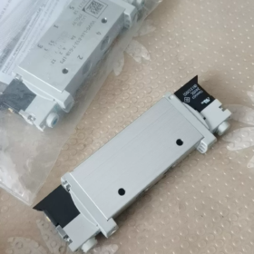
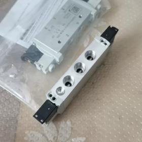
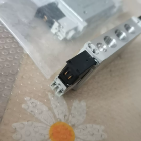
Material No.: 566500
Series: VUVG general-purpose solenoid valve, 14 mm valve width, 5/2 double stable (dual coil latching type), internal pilot operated
✅ Model Code Breakdown
| Segment | Definition |
| VUVG | Series: General-purpose solenoid valve, piston spool construction |
| L14 | 14 mm valve width, individual valve mounting (not valve island) |
| B52 | 5/2 5-way 2-position; B = double stable with dual coils |
| T | Internal pilot supply |
| G18 | Working ports G1/8″ |
| 1P3 | 24 VDC coil, P-style connector, 3-pin, IP65 with connector |
📋 Core Technical Specifications
Valve function: 5/2 5-way 2-position, double stable (memory type, maintains current position upon power loss)
Medium: Compressed air ISO 8573-1 [7:4:4], oil lubrication permitted
Operating pressure: 1.5 … 8 bar (0.15~0.8 MPa), vacuum operation not supported
Coil voltage: 24 V DC; coil power consumption: holding 0.3 W / pull-in 1.0 W, voltage tolerance ±10%
Flow rate: 700 ~ 780 l/min (DIN1343), nominal orifice 5.6 mm
Switching time: 8 ms
Protection rating: Valve body IP40; IP65 when fitted with connector
Manual override: Hidden, lockable manual pushbutton
Mounting orientation: Any position
Duty cycle: 100% continuous operation
Medium temperature: -5℃ ~ +50℃
Certifications: CE, UKCA, UL, RCM, RoHS
🧩 Structure & Application Notes
- Key double-stable characteristic: Only a short pulse signal is required to trigger commutation; valve position is retained after power cut. Continuous energization cannot maintain position; PLC programming must use pulse output.
- Internal pilot: Pilot air is tapped from the main air supply; no separate pilot air tubing required. Reliable commutation requires minimum pressure ≥1.5 bar.
- Throttle silencers may be fitted to exhaust ports to adjust cylinder speed.
- Application scenarios: Cylinder actuation in automation lines, manipulators, packaging equipment, assembly stations. Suitable for standalone mounting or assembly on valve island baseplates.
⚠️ Troubleshooting
No commutation: Supply pressure below 1.5 bar; no pulse signal to coil; jammed manual override; clogged pilot orifice.
Unstable operation: Contamination (water/oil) in compressed air; voltage drop exceeding 10%.
Automatic reset after power loss: Wrong model selected. Double-stable versions do not reset on power loss. Automatic reset is characteristic of single-stable models (B51).
🔁 Replacement / Interchange Reference
Original equivalent: VUVG-L14-B52-T-G18-1P3 (Material No. 566500)
Domestic alternative: Search for domestic 14 mm width 5/2 double stable solenoid valve, G1/8, 24VDC internal pilot
Similar model differentiation:
B51: Single stable (spring return), resets when power fails, not directly interchangeable with this model
-1R8L: Different connector type, incompatible electrical interface
📌 Customs HS Code Reference
Pneumatic solenoid valve HS: 8481804090 (Other pneumatic valves)
FESTO VUVG-L14-B52-T-G18-1P3 Internal Pilot Supply Principle (T=Internal Pilot)
Letter T in model = Internal pilot supply. Pilot air is taken directly from main inlet port Port 1 (P port) via internal passages inside the valve body, no external independent pilot tubing required.
The valve is a double stable 5/2 piston spool valve, composed of a pair of miniature pilot solenoid heads + main piston spool.
- Core Structure
- Main air circuit: Port 1 supply, Ports 2/4 connect to cylinder, Ports 3/5 exhaust. Main spool is a piston-type spool, shifted by air pressure. Solenoid coils cannot move the high-flow main spool directly.
- Pilot branch (internal air tapping): Small passages cast inside the valve body bleed a small stream of compressed air from main inlet Port 1 as pilot air, feeding to the valve chambers of left and right pilot solenoid heads.
- Two pilot solenoid heads (one on each side for B52 dual coil): Each side is a miniature 3/2 pilot valve; energization opens pilot air path, de-energization closes pilot air path.
- Pilot exhaust: Waste pilot air from pilot heads is vented through internal small passages to dedicated pilot exhaust openings on valve side, separate from main exhaust Ports 3/5 of the main valve.
- Full Operating Sequence (Internal Pilot)
Precondition: Port 1 supplied with compressed air ≥ 1.5 bar. Internal pilot passages remain filled with pilot air at the same pressure as main supply.
- Left coil receives 24VDC pulse signal
Electromagnetic force actuates the small pilot spool. Internally tapped pilot air (from Port1) is routed into left chamber of main piston spool. Pressure builds in left chamber and pushes main piston spool to the right.
Main valve commutation: 1→2 supply, 4→5 exhaust, cylinder extends.
Pulse signal lasts only tens of ms. Coil de-energizes after pulse, pilot small valve closes. Main spool retains position via air-locked (double stable memory) mechanism, continuous power is not required to hold position.
- Right coil receives 24VDC pulse signal
Right pilot head opens, pilot air enters right chamber of main piston, pushing main spool left.
Main valve commutation: 1→4 supply, 2→3 exhaust, cylinder retracts.
Position is maintained after pulse ends and coil de-energizes.
- Pilot exhaust
During commutation, residual pilot pressure from the opposite chamber of main piston is vented through the pilot exhaust path of the opposite pilot head to atmosphere via dedicated pilot vents.
- Internal Pilot vs External Pilot (VUVG Selection Key)
✅ Internal Pilot (T): Pilot air sourced from main supply Port1, no extra pilot tubing required. However, Port1 pressure ≥1.5 bar must be guaranteed, insufficient pressure prevents commutation; vacuum operation is not supported (no positive pressure at Port1 under vacuum, pilot cannot drive spool).
⚙️ External Pilot (M): Independent pilot ports 12/14, separate external pilot air supply isolated from main circuit; suitable for vacuum and low-pressure applications.
- Engineering Notes (Commissioning & Troubleshooting)
- Minimum pressure threshold: 1.5 bar. Below this value, internal pilot pressure cannot drive main piston spool and valve fails to switch.
- Pilot air is a small bleed from main supply, pilot flow rate is minimal and barely affects main cylinder flow. However, fluctuations in main supply pressure directly impact pilot driving force.
- Contamination risk: Water, oil and dust in compressed air may clog tiny internal pilot passages, causing sluggish switching or intermittent malfunction.
- Double-stable characteristic: Pilot air only performs the switching action and does not hold valve position. Once commutation completes, valve position remains locked even with temporary loss of main supply pressure, until a pulse triggers the opposite pilot coil.
- Summary in One Sentence
Internal pilot operation means a small branch of compressed air is taken internally from main inlet Port1 as actuation power. Solenoid coils only control miniature pilot valves; this internally tapped air pressure shifts the main piston spool to complete commutation, eliminating the need for separate pilot tubing.
FESTO VUVG Internal Pilot(T) vs External Pilot(M) Supply Principle Comparison
Applicable to your VUVG-L14-B52-T-G18-1P3 (T = internal pilot); suffix M in the same series = external pilot
- Core Principle Difference
✅ Internal Pilot (T, Internal Pilot Operated)
Pilot actuation gas = Air tapped internally from main inlet P (Port1)
Small pre-machined passages inside valve body bleed a small flow from main supply to feed left/right pilot solenoid heads to shift main spool.
No dedicated pilot port, no extra pilot air tubing needed.
Operating prerequisite: Main supply ≥1.5 bar. Main supply pressure equals pilot pressure.
Loss of main supply pressure removes pilot driving capacity directly; insufficient pressure prevents valve switching.
⚙️ External Pilot (M, External Pilot Operated)
Pilot actuation gas = Independent external pilot supply, fully isolated from main circuit
Valve body fitted with dedicated pilot supply ports (marked 12/14 on VUVG), pilot air supplied via separate external tubing.
Main circuit (Ports 1/2/3/4/5) and pilot circuit are two independent air circuits with no mutual interference.
Main circuit can operate at low pressure or even vacuum; spool commutation is achievable as long as pilot port has sufficient pressure.
Pilot supply pressure only drives main spool and is independent of medium pressure in main loop.
- Comparison Table
| Comparison Item | Internal Pilot T | External Pilot M |
| Pilot Air Source | Main inlet Port P (internal tapping) | Separate external pilot port (12/14) |
| Additional Pilot Tubing | ❌ Not required | ✅ Separate pilot tubing mandatory |
| Minimum Pressure Limit | Main supply ≥1.5 bar; valve fails to switch at lower pressure | Only pilot supply ≥1.5 bar required; no lower limit for main circuit pressure |
| Typical Application | Conventional compressed-air cylinder drive, vacuum not permitted | Vacuum, low-pressure main circuit, non-compressed-air process media |
| Cross Influence Between Circuits | Main supply pressure fluctuation directly affects switching performance | Main circuit pressure variation has no impact on pilot driving capability |
| Valve Ports | Only main ports 1,2,3,4,5 | Main ports + dedicated pilot supply ports |
| Installation & Commissioning | Wiring plus one main air tube only, simple piping | Extra pilot air tube and fittings, more complex layout |
| Cost | Lower valve price, fewer fittings, lower overall system cost | Higher valve cost, extra tubing and fittings required |
- Operating Logic Comparison (B52 Double Stable Example)
Internal Pilot(T)
- Compressed air fed to Port1; small internal orifice bleeds pilot air to both pilot solenoid heads on standby
- Pulse to one coil → pilot small valve opens → internal pilot pressure pushes main spool to switch
- After commutation completes, main spool air lock retains position, no power required after pulse
Key point: Without main compressed air supply, there is no pilot driving force and valve cannot switch.
External Pilot(M)
- Pilot port 12 continuously supplied with ≥1.5 bar compressed air (this provides actuation power)
- Main Port1 can be low pressure, vacuum or other medium
- Pulse to one coil → pilot small valve opens, external pilot pressure pushes main spool for commutation
- Position is retained by air lock after switching, same as internal pilot version
Key point: Main circuit pressure status does not affect commutation, as long as pilot supply remains available.
- Selection Guidance
Choose 【Internal Pilot T】
Standard pneumatic cylinders with main circuit using regular compressed air (≥2 bar)
Reduce tubing and fittings, simplify installation
Cost-sensitive standard cylinder drives on production lines (your VUVG-L14-B52-T-G18-1P3 belongs to this category)
Choose 【External Pilot M】
Vacuum chuck circuits (main port under vacuum with no positive pressure; internal pilot cannot function)
Main circuit medium pressure below 1.5 bar
Main circuit uses non-compressed-air special process gas requiring separate clean pilot air supply
- Common Misconceptions
- ❌ External pilot means pilot air holds valve position
✅ For B52 double stable valves, both internal and external pilot rely on spool air lock to maintain position. Pilot air only performs switching action; pilot pressure is not needed to hold position after commutation.
- ❌ External pilot requires high pressure in main circuit
✅ On the contrary, external pilot is designed for low-pressure or vacuum main circuits.
- ❌ Internal pilot exhaust shares main exhaust path
✅ For VUVG internal pilot variants, pilot waste air is discharged via dedicated pilot vents and does not pass through main exhaust Ports 3/5.
- Summary in One Sentence
Internal pilot: Uses compressed air from main circuit as actuation power, simple installation but main air must have sufficient pressure. External pilot: Dedicated independent air supply to drive spool; main circuit can run under vacuum or low pressure at the cost of more complex piping.



NH42-63-318x560.png "CHINT PC-type automatic transfer switches (ATS)NH42-63/4SZ")



