 Contactor,circuit breaker,solar inverter,electric meter,solar batteries

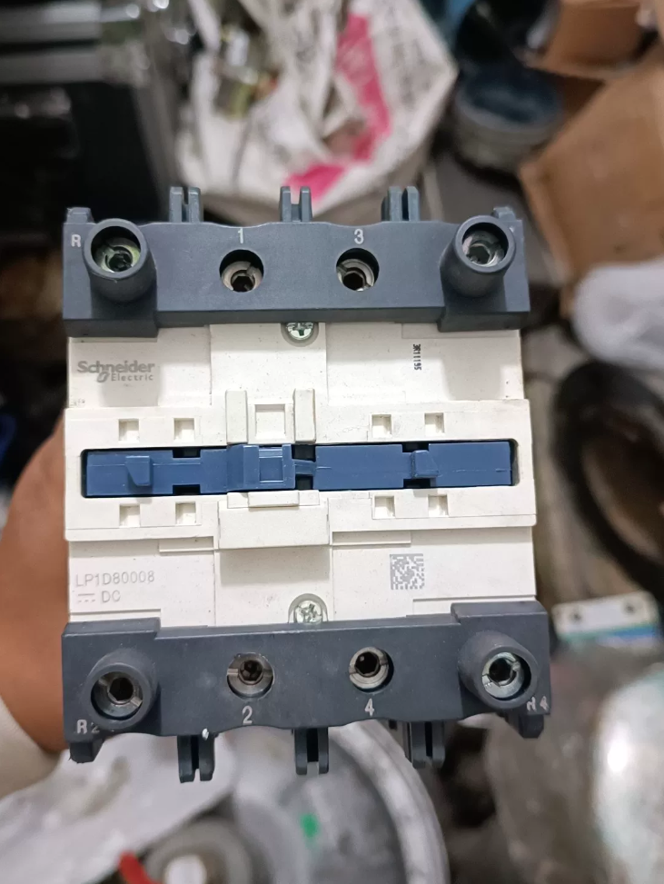

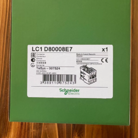

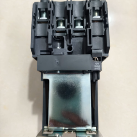
LC1D80008 Schneider TeSys D Series 4-Pole Contactor
This is a 4-pole AC contactor of Schneider Electric TeSys D Series, with main contacts configured as 2 Normally Open + 2 Normally Closed (2NO+2NC). Rated current: 80A (AC-3) / 125A (AC-1), suitable for resistive loads. The coil voltage suffix needs to be specified (e.g. B7=24VAC, G7=120VAC, M7=220VAC).
- Model Code Explanation (LC1D80008□7)
| Segment | Code | Description |
| LC1 | – | Schneider contactor series code (compliant with IEC standards) |
| D | – | TeSys D Series (Deca) |
| 80 | – | Reference rated operational current (80A under AC-3 duty) |
| 8 | – | 4-pole (2NO+2NC) main contact arrangement |
| □7 | Letter + Digit | Coil voltage code: B7=24VAC, D7=42VAC, G7=120VAC, M7=220VAC, U7=240VAC, Q7=380VAC, etc. |
Full Model Example: LC1D80008M7 = 4-pole (2NO+2NC), 80A, 220VAC coil
- Main Technical Specifications
| Item | Value | Remarks |
| Manufacturer | Schneider Electric | Telemecanique product line |
| Poles / Contact Configuration | 4P (2NO+2NC) | 2 normally open + 2 normally closed main contacts |
| Rated Operational Current | AC-1: 125A (≤440V) | AC-1: Resistive load; AC-3: Motor load |
| AC-3: 80A (400V) | ||
| Rated Insulation Voltage (Ui) | 690V (IEC) / 600V (UL/CSA) | Overvoltage Category III |
| Rated Operational Voltage (Ue) | ≤440V (AC-1) | 50/60Hz |
| Rated Impulse Withstand Voltage (Uimp) | 6kV | Compliant with IEC 60947 |
| Short-time Withstand Current (Icw) | 640A (40°C, 10s) | For power circuit |
| Rated Breaking Capacity | 1100A @ 440V | For power circuit |
| Coil Type | AC / DC optional | AC coil as standard |
| Terminal Connection | Screw clamp terminals | DIN rail mountable |
| Ingress Protection | IP20 | Standard version |
| Pollution Degree | 3 | Suitable for industrial environments |
| Mounting | 35mm DIN rail or panel mounting | Compliant with EN 50022 |
| Weight | Approx. 2.5kg | Excluding accessories |
- Full Model List (LC1D80008 Series)
| Model | Coil Voltage | Order Number | Remarks |
| LC1D80008B7 | 24V AC | LC1D80008B7 | Common control voltage |
| LC1D80008D7 | 42V AC | LC1D80008D7 | Special industrial application |
| LC1D80008G7 | 120V AC | LC1D80008G7 | Widely used in North America |
| LC1D80008M7 | 220V AC | LC1D80008M7 | Standard for Chinese market |
| LC1D80008U7 | 240V AC | LC1D80008U7 | Widely used in North America |
| LC1D80008Q7 | 380V AC | LC1D80008Q7 | Industrial high-voltage control |
| LC1D80008P7 | 400V AC | LC1D80008P7 | Standard for European market |
| LC1D80008E7 | 48V DC | LC1D80008E7 | DC control application |
| LC1D80008F7 | 110V DC | LC1D80008F7 | DC control application |
- Equivalent & Replacement Models
| Type | Model | Manufacturer | Compatibility | Remarks |
| Original Replacement | LC1D80008□7 | Schneider Electric | 100% | Direct replacement within the same series |
| Domestic Equivalent | CJX2-8004 | Chint / Delixi | Mechanically compatible | Minor differences in electrical parameters |
| ABB Equivalent | A145-30-11 | ABB | Functionally equivalent | Mounting dimensions need adjustment |
| Siemens Equivalent | 3RT2036-1BB40 | Siemens | Functionally equivalent | Coil voltage must be matched |
| Mitsubishi Equivalent | S-N80 | Mitsubishi | Functionally equivalent | Different auxiliary contact layout |
Obsolescence Notice: The LC1D80008 series is not discontinued and remains an active product of Schneider TeSys D range.
- Application & Industry Cases
5.1 Recommended Applications
Industrial heating systems: Control of resistance furnaces and electric heaters (AC-1 load)
Lighting systems: Lighting control for large workshops and malls (multi-circuit switching)
Capacitor banks: Switching for reactive power compensation (special accessories required)
UPS systems: Standby power switching control
Water treatment equipment: Control of water pumps and fans (derating required for AC-3 loads)
Building electrical systems: Control of central air conditioning and ventilation units
5.2 Not Recommended Applications
Frequently started/stopped motors: Rated current only 80A under AC-3 duty, not applicable for motors ≥45kW with frequent cycling
High vibration environments: Anti-vibration fixtures are mandatory
Corrosive environments: Anti-corrosion version or protective enclosure is required
Outdoor use without protection: Standard IP20 protection is insufficient
5.3 Typical Application Cases
Automotive manufacturing: Temperature control for oven furnaces in coating workshops. LC1D80008M7 controls three groups of heating elements for segmented temperature regulation.
Food processing: Dairy sterilization equipment. 4-pole design enables dual-circuit switching for main power and auxiliary heating.
Data centers: Linked control of fans and electric heaters for precision air conditioners to improve energy efficiency.
- Troubleshooting & Maintenance
6.1 Common Faults & Solutions
| Fault Phenomenon | Possible Causes | Troubleshooting Steps |
| Coil fails to pull in | 1. Insufficient coil voltage | 1. Measure coil voltage, ensure it is within ±10% of rated value |
| 2. Burned coil | 2. Test coil resistance (normal value: several hundred ohms) | |
| 3. Open circuit in control loop | 3. Check fuses, pushbuttons and wiring of control circuit | |
| Contact welding | 1. Overload / short circuit | 1. Check load current and replace damaged contacts |
| 2. Contact wear | 2. Replace contact assembly | |
| 3. Excessive operating frequency | 3. Reduce operation frequency or use higher-rated contactor | |
| Abnormal noise during operation | 1. Dirty core surface | 1. Clean core surface (power off first) |
| 2. Broken shading ring | 2. Replace shading ring | |
| 3. Fatigued spring | 3. Inspect and replace spring assembly | |
| Overheated coil | 1. Excessive supply voltage | 1. Adjust voltage to rated value |
| 2. Excessive ambient temperature | 2. Improve ventilation or apply derating | |
| 3. Aged coil insulation | 3. Replace coil | |
| Contact ablation | 1. Excessive load current | 1. Check load and select properly sized contactor |
| 2. Poor arc suppression | 2. Install surge suppressor | |
| 3. Defective contact material | 3. Replace original contact assembly |
6.2 Maintenance Schedule & Guidelines
Daily Inspection: Visually check for contact ablation, loose wiring and abnormal noise
Monthly Maintenance: Clean core surface, inspect contact wear
Quarterly Maintenance: Measure coil resistance, retighten all terminal screws
Annual Maintenance: Replace worn contacts, test insulation performance, verify pull-in and drop-out voltage
6.3 Quick Diagnosis Tips
Check power first if coil won’t act; test resistance when voltage is normal.
Check overload for welded contacts; clean core and inspect shading ring for noise.
Improve ventilation and derate for overheating; replace parts and suppress arc for ablated contacts.
- Selection & Installation Guidelines
7.1 Three-step Selection Procedure
- Confirm load type (AC-1 / AC-3) and rated current
- Select pole number and contact configuration (008 = 4P 2NO+2NC)
- Match coil voltage (B7 / G7 / M7, etc.)
7.2 Installation Notes
Reserve clearance ≥50mm for heat dissipation; avoid vertical stacking installation
Install surge suppressor (RC circuit or varistor) on control circuit
Ensure reliable mechanical interlock when used with thermal overload relays
Maintain spacing ≥20mm between adjacent contactors
7.3 Air Transport Compliance
No built-in lithium battery, compliant with air transportation safety regulations
CE certification number: Refer to product nameplate; complies with IEC 60947-4-1


, coil voltage of 110V AC, and is fitted with 1 Normally Open (1NO) auxiliary contact")
. Recommended replacements: LC1D115KUEC or LC1E120M5N")


CHINT Kunlun series AC contactor, upgraded compact structure replacing traditional CJX2 series")

")
NH42-63-318x560.png "CHINT PC-type automatic transfer switches (ATS)NH42-63/4SZ")


